Tài liệu Modeling, Measurement and Control P12 pdf
Bạn đang xem bản rút gọn của tài liệu. Xem và tải ngay bản đầy đủ của tài liệu tại đây (2.11 MB, 23 trang )
12
Semi-Active
Suspension Systems
12.1 Introduction
Vibration Isolation vs. Vibration Absorption •
Classification of Suspension Systems • Why
Semi-Active Suspension?
12.2 Semi-Active Suspensions Design
Introduction • Semi-Active Vibration Absorption
Design • Semi-Active Vibration Isolation Design
12.3 Adjustable Suspension Elements
Introduction • Variable Rate Dampers • Variable Rate
Spring Elements • Other Variable Rate Elements
12.4 Automotive Semi-Active Suspensions
Introduction • An Overview of Automotive
Suspensions • Semi-Active Vehicle Suspension
Models • Semi-Active Suspension Performance
Characteristics • Recent Advances in Automotive
Semi-Active Suspensions
12.5 Application of Control Techniques to
Semi-Active Suspensions
Introduction • Semi-Active Control Concept • Optimal
Semi-Active Suspension • Other Control Techniques
12.6 Practical Considerations and Related Topics
12.1 Introduction
Semi-active (SA) suspensions are those which otherwise passively generated damping or spring
forces modulated according to a parameter tuning policy with only a small amount of control effort.
SA suspensions, as their name implies, fill the gap between purely passive and fully active suspen-
sions and offer the reliability of passive systems, yet maintain the versatility and adaptability of
fully active devices. Because of their low energy requirement and cost, considerable interest has
developed during recent years toward practical implementation of these systems. This chapter
presents the basic theoretical concepts for SA suspensions’ design and implementation, followed
by an overview of recent developments and control techniques. Some related practical developments
ranging from vehicle suspensions to civil and aerospace structures are also reviewed.
12.1.1 Vibration Isolation vs. Vibration Absorption
In most of today’s mechatronic systems a number of possible devices, such as reaction or momentum
wheels, rotating devices, and electric motors are essential to the systems’ operations. These devices,
Nader Jalili
Clemson University
8596Ch12Frame Page 197 Friday, November 9, 2001 6:31 PM
© 2002 by CRC Press LLC
however, can also be sources of detrimental vibrations that may significantly influence the mission
performance, effectiveness, and accuracy of operation. Several techniques are utilized to either limit
or alter the vibration response of such systems. Vibration isolation suspensions and vibration
absorbers are quoted in the literature as the two most commonly used techniques for such utilization.
In vibration isolation either the source of vibration is isolated from the system of concern (also
called “force transmissibility, see Figure 12.1a), or the device is protected from vibration of its
point of attachment (also called displacement transmissibility, see Figure 12.1b). Unlike the isolator,
a vibration absorber consists of a secondary system (usually mass–spring–damper trio) added to
the primary device to protect it from vibrating (see Figure 12.1c). By properly selecting absorber
mass, stiffness, and damping, the vibration of the primary system can be minimized.
1
12.1.2 Classification of Suspension Systems
Passive, active, and semi-active are referred to in the literature as the three most common classifi-
cations of suspension systems (either as isolators or absorbers), see Figure 12.2.
2
A suspension
system is said to be active, passive, or semi-active depending on the amount of external power
required for the suspension to perform its function. A passive suspension consists of a resilient
member (stiffness) and an energy dissipator (damper) to either absorb vibratory energy or load the
transmission path of the disturbing vibration
3
(Figure 12.2a). It performs best within the frequency
region of its highest sensitivity. For wideband excitation frequency, its performance can be improved
considerably by optimizing the suspension parameters.
4-6
However, this improvement is achieved
at the cost of lowering narrowband suppression characteristics.
The passive suspension has significant limitations in structural applications where broadband
disturbances of highly uncertain nature are encountered. To compensate for these limitations, active
suspension systems are utilized. With an additional active force introduced as a part of suspension
subsection, in Figure 12.2b, the suspension is then controlled using different algorithms to
make it more responsive to source of disturbances.
2,7-9
A combination of active/passive treatment
is intended to reduce the amount of external power necessary to achieve the desired performance
characteristics.
10
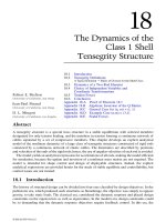
FIGURE 12.1
Schematic of (a) force transmissibility for foundation isolation, (b) displacement transmissibility
for protecting device from vibration of the base, and (c) application of vibration absorber for suppressing primary
system vibration.
(a)
(c)
(b)
Vibration
isolator
Vibration
isolator
source of
vibration
m
absorber
m
a
xa(t)
F(t) = F
0
sin
(
ω
t)
F(t) = F
0
sin
(
ω
t)
c
a
ck
m
device
source of
vibration
y(t) = Y
sin
(
ω
dt
t)
x(t) = X
sin
(
ω
t)
source of
vibration
k
a
Fixed base
Moving base
Absorber
subsection
F
T
c
k
Primary
device
ut()
8596Ch12Frame Page 198 Friday, November 9, 2001 6:31 PM
© 2002 by CRC Press LLC
12.1.3 Why Semi-Active Suspension?
In the design of a suspension system, the system is often required to operate over a wideband load
and frequency range which is impossible to meet with a single choice of suspension stiffness and
damping. If the desired response characteristics cannot be obtained, active suspension may provide
an attractive alternative vibration control for such broadband disturbances. However, active sus-
pensions suffer from control-induced instability in addition to the large control effort requirement.
This is a serious concern that prevents common usage in most industrial applications. On the other
hand, passive suspensions are often hampered by a phenomenon known as “de-tuning.” De-tuning
implies that the passive system is no longer effective in suppressing the vibration as it was designed
to do. This occurs because of one of the following reasons: (1) the suspension structure may
deteriorate and its structural parameters can be far from the original nominal design, (2) the
structural parameters of the primary device itself may alter, or (3) the excitation frequency and/or
nature of disturbance may change over time.
Semi-active (also known as adaptive-passive) suspension addresses these limitations by effec-
tively integrating a tuning control scheme with tunable passive devices. For this, active force
generators are replaced by modulated variable compartments such as a variable rate damper and
stiffness, see Figure 12.2c.
11-13
These variable components are referred to as “tunable parameters”
of the suspension system, which are retailored via a tuning control and thus result in semi-actively
inducing optimal operation. Much attention is being paid to these suspensions for their low energy
requirement and cost. Recent advances in smart materials and adjustable dampers and absorbers
have significantly contributed to the applicability of these systems.
14-16
12.2 Semi-Active Suspensions Design
12.2.1 Introduction
SA suspensions can achieve most of the performance characteristics of fully active systems, thus
allowing for a wide class of applications. The idea of SA suspension is very simple: to replace
active force generators with continually adjustable elements which can vary and/or shift the rate
of energy dissipation in response to an instantaneous condition of motion. This section presents
basic understanding and fundamental principles and design issues for SA suspension systems,
which are discussed in the form of a vibration absorber and vibration isolator.
12.2.2 Semi-Active Vibration Absorption Design
With a history of almost a century,
17
vibration absorbers have proven to be useful vibration
suppression devices, widely used in hundreds of diverse applications. It is elastically attached to
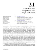
FIGURE 12.2
A typical primary structure equipped with three versions of suspension systems: (a) passive, (b)
active, and (c) semi-active configuration.
Suspension
subsection
Primary or
foundation
system
Suspension point of attachment
(a) (b) (c)
x
c
c
c
(
t
)
k
(
t
)
u
(
t
)
k
k
m
m
m
x
x
8596Ch12Frame Page 199 Friday, November 9, 2001 6:31 PM
© 2002 by CRC Press LLC
the vibrating body to alleviate detrimental oscillations from its point of attachment (see Figure 12.2).
The underlying proposition for an SA absorber is to properly adjust the absorber parameters so
that it absorbs the vibratory energy within the frequency interval of interest.
To explain the underlying concept, a single-degree-of-freedom (SDOF) primary system with a
SDOF absorber attachment is considered (Figure 12.3). The governing dynamics are expressed as
(12.1)
(12.2)
where
x
p
(
t
) and
x
a
(
t
) are the respective primary and absorber displacements,
f
(
t
) is the external
force, and the rest of the parameters including adjustable absorber stiffness
k
a
and damping
c
a
are
defined per Figure 12.3. The transfer function between the excitation force and primary system
displacement in Laplace domain is then written as
(12.3)
where
(12.4)
and
X
a
(
s
),
X
p
(
s
), and
F
(
s
) are the Laplace transformations of
x
a
(
t
),
x
p
(
t
), and
f
(
t
), respectively.
The steady-state displacement of the system due to harmonic excitation is then
(12.5)
where is the disturbance frequency and . Utilizing adjustable properties of the SA unit
(i.e., variable rate damper and spring), an appropriate parameter tuning scheme is selected to
minimize the primary system’s vibration subject to external disturbance
f
(
t
).
FIGURE 12.3
Application of a semi-active abosrber to SDOF primary system with adjustable stiffness
k
a
and
damping
c
a
.
c
p
k
p
c
a
k
a
f(t)
m
p
m
a
x
a
x
p
mx t cx t kx t cx t kx t
aa aa aa ap ap
˙˙ ˙ ˙
()
+
()
+
()
=
()
+
()
mx t c c x t k k x t cx t kx t ft
pp p a p p a p aa aa
˙˙ ˙ ˙
()
++
()
()
++
()
()
−
()
−
()
=
()
TF s
Xs
Fs
ms cs k
Hs
p
aaa
()
()
() ()
==
++
2
Hs ms c csk k ms csk csk
p pa paa aa aa
() ( ) ( ) ( )=++++
{}
++− +
222
Xj
Fj
km jc
Hj
p
aa a
()
() ()
ω
ω
ωω
ω
=
−+
2
ω
j =−1
8596Ch12Frame Page 200 Friday, November 9, 2001 6:31 PM
© 2002 by CRC Press LLC
12.2.2.1 Harmonic Excitation
When excitation is tonal, the absorber is generally tuned at the disturbance frequency. For complete
attenuation, the steady state must equal zero. Consequently, from Equation (12.5), the
ideal stiffness and damping of SA absorber are adjusted as
(12.6)
Note that this tuned condition is only a function of absorber elements (
m
a
,
k
a
, and
c
a
). That
is, the absorber tuning does not need information from the primary system and hence its design
is stand-alone. For tonal applications, theoretically zero damping in an absorber subsection results
in improved performance. In practice, however, damping is incorporated to maintain a reasonable
trade-off between the absorber mass and its displacement. Hence, the design effort for this class
of applications is focused on having precise tuning of an absorber to the disturbance frequency
and controlling damping to an appropriate level. Referring to Snowdon,
18
it can be proven that
the absorber, in the presence of damping, can be most favorably tuned and damped if adjustable
stiffness and damping are selected as
(12.7)
12.2.2.2 Broadband Excitation
In broadband vibration control, the absorber subsection is generally designed to add damping to and
change the resonant characteristics of the primary structure to maximally dissipate vibrational energy
over a range of frequencies. The objective of SA suspension design is, therefore, to adjust the
absorber
parameters
to minimize the peak magnitude of the frequency transfer function ( )
over the absorber variable suspension parameters . That is, we seek
p
to
(12.8)
Alternatively, one may select the mean square displacement response (MSDR) of the primary
system for vibration suppression performance. That is, the absorber variable parameters’ vector
p
is selected such that the MSDR
(12.9)
is minimized over a desired wideband frequency range.
S
(
ω
) is the power spectral density of the
excitation force
f
(
t
), and FTF was defined earlier.
This optimization is subjected to some constraints in
p
space, where only positive elements are
acceptable. Once the optimal absorber suspension properties,
c
a
and
k
a
, are determined they can
be implemented using adjustment mechanisms on the spring and the damper elements. This is
viewed as a semi-active adjustment procedure as it introduces no added energy to the dynamic
structure. The conceptual devices for such adjustable suspension elements will be discussed later
in 12.3.
Xj
p
()ω
km c
aa a
== ω
2
0,
k
mm
mm
cm
k
mm
opt
ap
ap
opt a
opt
ap
=
+
=
+
22
2
3
2
ω
()
,
()
FTF TF s
sj
() ()ω
ω
=
=
p =
{}
ck
aa
T
min max ( )
min
max
p
ω
ωω
ω
≤≤
{}
FTF
E x FTF S d
p
{( )} () ()
2
0
2
=
{}
∞
∫
ωωω
8596Ch12Frame Page 201 Friday, November 9, 2001 6:31 PM
© 2002 by CRC Press LLC
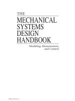
12.2.2.3 Simulations
To better recognize the effectiveness of the SA absorber over the passive and optimum passive
absorber settings, a simple example case is presented. For the simple system shown in Figure 12.3,
the following nominal structural parameters (marked by over score) are taken:
(12.10)
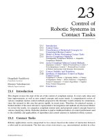
These are from an actual test setting which is optimal by design. That is, the peak of FTF is
minimized (see thinner line in Figure 12.4). When the primary stiffness and damping increase 5%
(for instance, during the operation), the FTF of the primary system deteriorates considerably (dashed
line in Figure 12.4), and the absorber is no longer an optimum one for the present primary. When
the absorber is optimized based on optimization problem (12.8), the re-tuned setting is reached as
(12.11)
which yields a much better frequency response (see darker line in Figure 12.4).
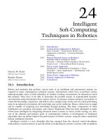
The SA absorber effectiveness is better demonstrated at different frequencies by a frequency
sweep test. For this, the excitation amplitude is kept fixed at unity and its frequency changes every
0.15 seconds from 1860 to 1970 Hz. The primary response with nominally tuned, with de-tuned,
and with re-tuned absorber settings are given in Figures 12.5a, b, and c, respectively.
12.2.3 Semi-Active Vibration Isolation Design
The parameter tuning control scheme for an SA isolator is similar to that of an SA vibration
absorber, with the only difference being in the derivation of the transfer function. The classical
isolator system shown in Figure 12.1a and b consists of a rigid body of mass
m
, linear spring
k,
and viscous damping
c
. Conversely, for a vibration absorber, the function of the isolator is to reduce
the amplitude of motion transmitted from a moving support to the body (Figure 12.1b), or to reduce
the magnitude of the force transmitted from the body to the foundation to an acceptable level
(Figure 12.1a).
The transfer functions between isolated mass displacement and base displacement or transmitted
force to foundation and excitation force are expressed as
FIGURE 12.4
Frequency transfer functions (FTF) for nominal absorber (thin-solid); de-tuned absorber (thin-
dotted); and re-tuned absorber (thick-solid) settings. (From N. Jalili and N. Olgac, 2000,
Journal of Guidance,
Control, and Dynamics,
23 (6), 961–990. With permission.)
0.0
0.2
0.4
0.6
0.8
1.0
200 400 600 800 1000 1200 1400 1600 1800
Frequency, Hz.
FTF
nominal absorber de-tuned absorber re-tuned absorber
Peak values:
Nominally tuned
De-tuned
Re-tuned
0.82
0.99
0.86
mkgk Nmc kgs
mkgk Nmc kgs
pp p
aa a
==× =
==× =
5 77 251 132 10 197 92
0 227 9 81 10 355 6
6
6
., . /, . /
., . /, ./
k N m c kg s
aa
=× =10 29 10 364 2
6
./, ./
8596Ch12Frame Page 202 Friday, November 9, 2001 6:31 PM
© 2002 by CRC Press LLC
(12.12)
(12.13)
FIGURE 12.5
Frequency sweep each 0.15 with frequency change of [1860, 1880, 1900, 1920, 1930, 1950, 1970]
Hz: (a) nominally tuned absorber, (b) de-tuned absorber, and (c) re-tuned absorber settings. (From N. Jalili and N.
Olgac, 2000,
Journal of Guidance, Control, and Dynamics,
23 (6), 961–990. With permission.)
(a)
(b)
(c)
-1.75
-1.25
-0.75
-0.25
0.25
0.75
1.25
1.75
0.00 0.10 0.20 0.30 0.40 0.50 0.60 0.70 0.80 0.90
time (sec)
Non-dimensionless disp.
-1.75
-1.25
-0.75
-0.25
0.25
0.75
1.25
1.75
0.00 0.10 0.20 0.30 0.40 0.50 0.60 0.70 0.80 0.90
time (sec)
Non-dimensionless disp.
Max amplitude: 1.1505
Max amplitude: 1.5063
Max amplitude: 1.0298
-1.75
-1.25
-0.75
-0.25
0.25
0.75
1.25
1.75
0.00 0.10 0.20 0.30 0.40 0.50 0.60 0.70 0.80 0.90 1.00
time (sec)
Non-dimensionless disp.
F
F
Xs
Ys
s
ss
T
nn
nn0
2
22
2
2
==
+
++
()
()
ζω ω
ζω ω
Xs
Fs
m
ss
nn
()
()
/
=
++
1
2
22
ζω ω
8596Ch12Frame Page 203 Friday, November 9, 2001 6:31 PM
© 2002 by CRC Press LLC
where is the damping ratio, is the natural frequency, and
F
T
is the ampli-
tude of the transmitted force to the foundation (see Figure 12.1a).
Figure 12.6 shows the transmissibility
T
A
( ) as a function of the frequency
ratio and the damping ratio , where the low frequency range in which the mass displacement
essentially follows the base excitation, , is separated from the high-frequency range of iso-
lation, . Near resonance, the
T
A
is determined completely by the value of the damping ratio.
A fundamental problem is that while a high value of the damping ratio suppresses the resonance,
it also compromises the isolation for the high-frequency region ( ).
Similar to optimum vibration absorber, an optimal transfer function for the isolator can be
obtained as
(12.14)
where and depends upon the weighting factor between mean square acceleration
and mean square rattle space in the criterion function used for optimization (similar to problem
(12.8) except with transfer function (12.14).
20
The frequency response plot of this transfer function
as shown in Figure 12.7 indicates that the damping values sufficient to control the resonance have
no adverse effect on high-frequency isolation.
12.2.3.1 Variable Natural Frequency
Similar to an SA absorber, an SA isolator can be utilized for disturbances with time-varying
frequency. The variation of natural frequency (which is a function of suspension stiffness) with the
transmissibility
T
A
, in the absence of damping, is given as
(12.15)
FIGURE 12.6
Frequency response plot of transmissibility
T
A
for the semi-active suspension as a function of
variable damping ratio.
10
-2
10
-1
10
0
10
1
10
-1
10
0
10
1
w/wn
A
T
Amplification occurs
Isolation occurs
= 1.0
0.707
0.5
0.25
0.10
0.0
ζ
ζ=ckm/2
ω
n
km= /
TFFXY
AT
==//
0
ζ
XY=
XY<
ωω>
n
TF s
X
Ys s
n
opt opt n
()==
++
ω
ζω ω
2
22
2
ζ
opt
= 22,
ω
opt
ωω
nAAA
TT T=+≤≤ /( ),101
8596Ch12Frame Page 204 Friday, November 9, 2001 6:31 PM
© 2002 by CRC Press LLC
With variable disturbance frequency, , and desired transmissibility
T
A
, the natural frequency (or
the suspension stiffness
k
) can be changed in accordance with Equation (12.15) to arrive at optimal
performance operation.
21
12.3 Adjustable Suspension Elements
12.3.1 Introduction
Adjustable suspension elements typically are comprised of a variable rate damper and stiffness.
Significant efforts have been devoted to the development and implementation of such devices for
a variety of applications. Examples of such devices include electro-rheological (ER),
22-24
magneto-
rheological (MR)
25,26
fluid dampers, variable orifice dampers,
27,28
controllable friction braces,
29
controllable friction isolators,
30
and variable stiffness and inertia devices.
12,31-34
The conceptual
devices for such adjustable properties are briefly reviewed in this section.
12.3.2 Variable Rate Dampers
A common and very effective way to reduce transient and steady-state vibration is to change the
amount of damping in the SA suspension. Considerable design work of semi-active damping was
done in the 1960s through 1980s
35,36
for vibration control of civil structures such as buildings and
bridges
37
and for reducing machine tool oscillations.
38
Since then, SA dampers have been utilized
in diverse applications ranging from trains
39
and other off-road vehicles
40
to military tanks.
41
During
recent years considerable interest in improving and refining the SA concept has arisen in indus-
try.
42,43
Recent advances in smart materials have led to the development of new SA dampers, which
are widely used in different applications.
In view of these SA dampers, electro-rheological (ER) and magneto-rheological (MR) fluids
probably serve as the best potential hardware alternatives for the more conventional variable-orifice
hydraulic dampers.
44,45
From a practical standpoint, the MR concept appears more promising for
FIGURE 12.7 Frequency response plot of transmissibility T
A
for optimum semi-active suspension as a function
of variable damping ratio.
10
-1
10
0
10
1
10
-2
10
-1
10
0
10
1
w/wn
A
T
ζ = 0.10
0.25
0.50
0.707 (optimal)
10
ω
8596Ch12Frame Page 205 Friday, November 9, 2001 6:31 PM
© 2002 by CRC Press LLC
suspension because it can operate, for instance, on a vehicle’s battery voltage, whereas the ER
damper is based on high-voltage electric fields. Due to their importance in today’s SA damper
technology, we briefly review their operation and fundamental principles.
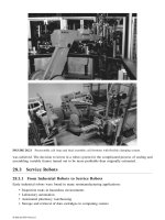
12.3.2.1 Electro-Rheological (ER) Fluid Dampers
ER fluids are materials which undergo significant instantaneous reversible changes in material
characteristics when subjected to electric potentials (Figure 12.8). The most significant change is
associated with complex shear moduli of the material, and hence ER fluids can be usefully exploited
in SA suspensions where variable rate dampers are utilized. The idea of applying an ER damper
to vibration control was initiated in automobile suspensions, followed by other applications.
46,47
The flow motion of an ER fluid-based damper can be classified by shear mode, flow mode, and
squeeze mode. However, the rheological property of ER fluid is evaluated in the shear mode.
23
Under the electrical potential, the constitutive equation of a ER fluid damper has the form of
Bingham plastic
48
(12.16)
where τ is the shear stress, is the fluid viscosity, is shear rate, and is yield stress of the
ER fluid which is a function of the electric field E. The coefficients α and β are intrinsic values,
which are functions of particle size, concentration, and polarization factors.
Consequently, the variable damping force in shear mode can be obtained as
(12.17)
where h is the electrode gap, L
d
is the electrode length of the moving cylinder, r is the mean radius
of the moving cylinder, is the transverse velocity of the ER damper, and represents the
signum function (Figure 12.8). As a result, the ER fluid damper provides an adaptive viscous and
frictional damping for use in SA systems.
24,49
FIGURE 12.8 A schematic configuration of an ER damper. (From S. B. Choi, 1999, ASME Journal of Dynamic
Systems, Measurement and Control, 121, 134–138. With permission.)
Moving cylinde
r
Fixed
cup
ER Fluid
r
h
L
a
L
a
Aluminum
foil
y.
.
y
τηγτ τ α
β
=+ = and
˙
(), ()
yy
EEE
η
˙
γ τ
y
E()
FrLyhEy
ER
d
=+
{}
4πη α
β
˙
/ .sgn(
˙
)
˙
y
sgn( )⋅
8596Ch12Frame Page 206 Friday, November 9, 2001 6:31 PM
© 2002 by CRC Press LLC
12.3.2.2 Magneto-Rheological (MR) Fluid Dampers
MR fluids are the magnetic analogs of ER fluid and typically consist of micron-sized, magnetically
polarizable particles dispersed in a carrier medium such as mineral or silicon oil. When a magnetic
field is applied, particle chains form and the fluid becomes a semisolid, exhibiting plastic behavior
similar to that of ER fluids (Figure 12.9). Transition to rheological equilibrium can be achieved in
a few milliseconds, providing devices with high bandwidth.
25,26,50
Similar to Bigham’s plasticity model of (12.16), the behavior of controllable fluid is represented by
(12.18)
where H is the magnetic field. Most devices that use MR fluids can be classified as having either
fixed poles (pressure-driven flow mode) or relatively movable poles (direct shear mode). In a manner
like ER dampers, the variable force developed by an MR damper in direct-shear mode is
(12.19)
where is the relative pole velocity, is the shear (pole) area, and the rest of the parameters
are similar to those in the ER notations used in Figure 12.8.
12.3.3 Variable Rate Spring Elements
In contrast to studies of variable dampers, those of SA springs or time-varying stiffness have been
geared for vibration isolation applications,
51
for structural controls, and for vibration attenuation
(Reference 2 and references therein). The variable stiffness is a promising practical complement
to SA damping, because, based on the discussion in Section 12.2, both the suspension damping
and stiffness should change to optimally adapt to different conditions. Clearly, suspension stiffness
has a significant influence on optimum operation (even more over the damping element
52
).
Unlike the variable rate damper, changing the effective stiffness requires high energy.
32
Semi-
active or low-power implementation of variable stiffness techniques suffers from a limited frequency
range, complex implementation, high cost, etc.
12,33,34
Therefore, in practice, both absorber damping
and stiffness are concurrently adjusted to reduce the required energy.
FIGURE 12.9 A schematic configuration of an MR damper.
τηγτ=+
˙
()
y
H
FAyhHA
MR y
=+ητ
˙
/()
˙
y
ALw=
8596Ch12Frame Page 207 Friday, November 9, 2001 6:31 PM
© 2002 by CRC Press LLC
12.3.3.1 Variable Rate Stiffness (Direct Methods):
The primary objective is to directly change the spring stiffness to optimize a vibration suppression
characteristic such as Equation (12.8) or (12.9). Different techniques can be utilized from traditional
variable leaf-spring to smart-spring utilizing magnetostrictive materials. A tunable stiffness vibra-
tion absorber was utilized for a four-DOF building (Figure 12.10), where a spring is threaded
through a collar plate and attached to the absorber mass from one side and to the driving gear from
the other side.
34
Thus, the effective number of coils, N, can be changed resulting in a variable spring
stiffness k
a.
(12.20)
where d is the spring wire diameter, D is the spring diameter, and G is the modulus of shear rigidity.
12.3.3.2 Variable Rate Effective Stiffness (Indirect Methods):
In most SA applications, directly changing the stiffness may not always be possible or may require
a large amount of control effort. For such cases, alternatives methods are utilized to change the
effective tuning ratio ( ), thus resulting in a tunable resonance frequency.
In Liu
53
a semi-active flutter suppression scheme was proposed using differential changes of the
external store stiffness. As shown in Figure 12.11, the motor drives the guide screw to rotate with
slide block G moving along it, thus changing the restoring moment and resulting in a change of
store-pitching stiffness. Using a double-ended cantilever beam carrying intermediate lumped
masses, a semi-active vibration absorber was recently introduced,
54
where the position of moving
masses was adjustable (see Figure 12.12). Figure 12.13 shows an SA absorber with an adjustable
FIGURE 12.10 The application of a variable stiffness vibration absorber to a four-DOF building. (From M.A.
Franchek, M.W. Ryan, and R.J. Bernhard, 1995, Journal of Sound and Vibration, 189(5), 565–585. With permission.)
FIGURE 12.11 A semi-active flutter control using adjustable pitching stiffness. (From H. J. Liu, Z. C. Yang, and
L. C. Zhao, 2000, Journal of Sound and Vibration, 229(1), 199–205. With permission.)
S
Left wing tip
β
G
k
dG
DN
a
=
4
3
8
τω= km
a a primary
8596Ch12Frame Page 208 Friday, November 9, 2001 6:31 PM
© 2002 by CRC Press LLC
effective inertia mechanism.
55
The SA absorber consists of a rod carrying a moving block and a
spring and damper mounted on a casing. The position of the moving block, r
v
, on the rod is
adjustable, which provides a tunable resonance frequency.
12.3.4 Other Variable Rate Elements
Recent advances in smart materials have led to the development of new SA suspensions using
indirect influence on the suspension elements. A semi-active piezoelectric network was utilized
16
FIGURE 12.12 A typical primary system equipped with the double-ended cantilever absorber with adjustable
tuning ration through moving masses m. (From N. Jalili, 2000, Proceedings of 2000 International Mechanical
Engineering Congress and Exposition, Orlando, FL. With permission.)
FIGURE 12.13 Schematic of the adjustable effective inertia vibration absorber. (From N. Jalili, B. Fallahi, and
Z. K. Kusculuoglu, 2001, International Journal of Modelling and Simulation, 21(2), 148–154. With permission.)
K
C
M
q(t)
)sin( tA
exc
f
e
ω=
m
m
L
a
r
v
r
a
r
s
l
s
,m
s
h
k
a
C
a
l
v
,m
v
m
p
g
b
m
p
k
p
k
p
k
p
k
e
C
e
C
p
k
p
C
p
y
e
4
4
4
2
y
p
8596Ch12Frame Page 209 Friday, November 9, 2001 6:31 PM
© 2002 by CRC Press LLC
for structural vibration control. The variable resistance and inductance in an external RL circuit
are used as real-time adaptable control parameters.
Another class of adjustable suspensions is the so-called hybrid treatment.
56
The hybrid design
has two modes: active and passive. With the aim of lowering the control effort, relatively small
vibrations are reduced in the active mode, while the passive mode is used for large oscillations.
Analogous to hybrid treatment, the semi-automated approach combines semi-active and active
suspensions to benefit the advantages of individual schemes while eliminating their shortfalls.
57
By
altering the adjustable structural properties (in a semi-active unit) and control parameters (in an
active unit), a search is conducted to minimize an objective function subject to certain constraints,
which may reflect performance characteristics.
12.4 Automotive Semi-Active Suspensions
12.4.1 Introduction
Earlier studies on SA suspensions focused on automobile-related applications. One notable reason
is that the importance of energy dissipation in suspension systems is recognized most in automotive
suspensions, where ride comfort and vehicle handling are encountered. For this reason, a section
is devoted to the application of SA systems to automotive suspension. The objectives here are to
briefly review the fundamental design aspects in automobile semi-active suspension and present
some recent developments in this area.
12.4.2 An Overview of Automotive Suspensions
Advanced vehicle suspension systems such as adaptive, semi-active, and active have been used
extensively in most conventional ground transport fleets. Due to slow response time in adaptive
systems and high energy consumption and cost in active suspensions, they are unlikely to survive
in the future market. Recently, much attention is being paid to controllable active or semi-active
elements.
58-60
Due to the large forces and velocities involved in suspension systems, it is important to minimize
the actuator power requirement for practical and economical reasons.
36
For the actuator in semi-
active suspension systems, multistage dampers and continuously variable dampers,
36
or variable
lever ratio systems and modulated transformers are being utilized. These suspensions are called
low bandwidth or fast load lever systems and often incorporate semi-active dampers which produce
high-frequency controllable forces with low power requirements.
In vehicle suspensions, physical actuator limitations or cost considerations may render an elegant
design concept totally impractical. For this reason, interest has surfaced in exploring the possibility
of improving suspension performance by modulating the characteristics of essentially passive
elements such as springs and dampers. SA suspensions represent a compromise between perfor-
mance improvement and simplicity of implementation.
12.4.3 Semi-Active Vehicle Suspension Models
Different models are used for the design of a SA suspension. These models range from the simplest
one, a single DOF quarter car model which allows for only one-dimensional vertical or heave
motion, to very complex with many DOFs.
60,61
To illustrate the theoretical concepts and avoid
disturbing the focus of the subject, we briefly discuss using a simple quarter car (SQC) model
(Figure 12.14), which may be achieved by linear damping and spring stiffness variations. Although
this is a simple model, it is quite suitable to study the performance of vehicle suspension in both
bounce motion and tire deflection.
62
8596Ch12Frame Page 210 Friday, November 9, 2001 6:31 PM
© 2002 by CRC Press LLC
The governing equations of motion for the sprung and unsprung masses are
(12.21)
where m
1
is a quarter of the body mass (sprung), m
2
is the mass of the wheel, b and k
1
are the adjustable
damping and stiffness of the suspension, and the rest of the parameters are defined in Figure 12.14.
Figure 12.15 shows such an adjustable damper, whereby the check valves assure that for both
directions of piston motion, the hydraulic fluid flows the same way through a solenoid-controlled
blow-off valve, thus resulting in variable damping. To demonstrate the effect of suspension element
variations on ride comfort, the frequency response of body velocity (as a measure of ride comfort)
is shown in Figure 12.16. The adjustable damper and stiffness are optimized with respect to ride
comfort, suspension rattle space, and road handling. A performance characteristic is then constructed
to perform this optimization.
12.4.4 Semi-Active Suspension Performance Characteristics
It is important to recognize that automobile suspension must perform several tasks in addition to
isolating the body from vibration induced by road unevenness.
59
The body attitude, the attitude of
each wheel with respect to road surface, dynamic normal force variations at each wheel, and many
other criteria must be controlled. Although the focus here is on vibration isolation of suspension
systems, a good design should allow for meeting several conflicting requirements.
An optimal SA control problem is, therefore, formulated (for the SQC model of Figure 12.14)
to briefly highlight the design procedure. For the performance index (PI) in the design of vehicle
suspension, sprung mass acceleration, suspension travel, and tire spring excursion can be incorpo-
rated. Sprung mass acceleration is a measure of body isolation, i.e., passenger ride comfort.
Suspension travel or rattle space is typically a design constraint for limiting rigid body motion of
the vehicle. Tire spring stroke (or equivalently, dynamic tire force) is an indicator of road-holding
ability. Accordingly, a PI of the following form can be selected:
(12.22)
FIGURE 12.14 An SQC model of vehicle suspension system.
m
1
m
2
k
1
b
v
(
t
)
z
2
(
t
)
z
0
(
t
)
z
1
(
t
)
k
2
mz k z z b z z
mz k z z bz z k z z
11 1 1 2 1 2
22 1 2 1 2 1 2 2 0
0
0
˙˙
()(
˙˙
)
˙˙
()(
˙˙
)( )
+−+−=
+−+−+−=
PI
T
Ez zz zzdt
T
=+−+−
{}
∫
1
2
12
2
21 0
2
32 1
2
0
γγ γ
˙˙
()()
8596Ch12Frame Page 211 Friday, November 9, 2001 6:31 PM
© 2002 by CRC Press LLC
where E denotes the expectations necessary because of the random road disturbance input z
0
; T is
a sufficient large endtime; and γ
1
, γ
2
, and γ
3
are weighting factors for the penalized variables.
Given the linear system described by Equation (12.21), a control sequence U(t) can be chosen
to minimize the PI given in Equation (12.22), under the passivity constraint
13
(12.23)
FIGURE 12.15 Schematic design of the Nissan electro-hydraulic valve in the piston of a semi-active damper.
FIGURE 12.16 Variations in frequency response of body velocity for SQC model with variable damper. (From
D. Karnopp, 1995, ASME Transactions, Special 50th Anniversary, Design Issue, 117, 177–185. With permission.)
V /VO [BP: BPN/4 TO BPN x 4]
MAGNITUDE
FREQUENCY [HZ]
10
-1
10
-2
10
-1
10
0
10
1
2
2
5
2
5
2
5
2552510
0
10
1
10
2
Ut z t z t , t T()
˙
()
˙
()
12
00−
[]
≥≤≤
8596Ch12Frame Page 212 Friday, November 9, 2001 6:31 PM
© 2002 by CRC Press LLC
In addition, because the vehicle structure can tolerate only bounded suspension forces it is
required that
(12.24)
where is the maximal allowed force. Many exact (numerical) and approximate (analytical)
solutions to this problem exist. We leave the details to Hrovat, Margolis, and Hubbard
13
and
Hrovat.
61
12.4.5 Recent Advances in Automotive Semi-Active Suspensions
The SA concept has been applied to a broad class of ground transport fleets, ranging from tractors
and other farm vehicles to high-speed ground transportation vehicles. The SA suspension concept
goes back to the early 1970s
35
in the form of variable, controllable damping. Although the focus
here is on vibration isolation through vehicle suspension design, it is worthwhile mentioning
that a few applications of vibration absorber with the aim of improving ride comfort have been
used (see Figure 12.17).
64
Some developments include SA suspension with variable stiffness,
65
electro-hydro-pneumatic
slow-active suspension,
66
SA suspension using ER fluid mount,
67
fast load-lever suspension with
a variable lever rate,
68
SA gas suspension for off-road vehicles,
40
SA suspension for passenger
trains,
39
and SA suspension using a piston-controlled disk valve.
28
12.5 Application of Control Techniques
to Semi-Active Suspensions
12.5.1 Introduction
As discussed in the preceding section, the SA suspension generates forces passively, but these
forces are modulated continuously in accordance with some prescribed control law with only small
FIGURE 12.17 A two-DOF vehicle model with dynamic vibration absorber.
U
b
a
z
1
(t)
Sprung mass
m
1
k
2
Unsprung mass
m
2
Road surface irregularities
z
2
(t)
z (t)
Absorber mass
m
a
U
k
a
z
a
(t)
Ut U t T
M
() ,≤≤≤0
U
M
> 0
8596Ch12Frame Page 213 Friday, November 9, 2001 6:31 PM
© 2002 by CRC Press LLC
amount of external power. In other words, SA suspension is basically a device with time-varying
controllable damping and spring.
The concept of SA control
36
has been developed and demonstrated to be a viable suspension
alternative. Although not rigorously proven, damper and stiffness can be treated much like active
force generators for the purpose of controller design. That is, the SA damper or spring is modulated
according to the same control policy and same sate measurement as its fully active force generator
counterpart. Obviously, the sign of the damper or spring force is dictated by the relative motion
across it, and thus cannot be specified. This section briefly reviews the control techniques for SA
suspensions.
12.5.2 Semi-Active Control Concept
The elementary SA controller design is the so-called on-off SA strategy, which was first proposed
by Margolis, Tylee, and Hrovat.
69
It switches the damper off whenever sprung and unsprung masses
move in the same direction and unsprung mass has a larger velocity. In any other situations the
damper is set to the on position. The schematic of the conceptual control law is shown in
Figure 12.18.
A somewhat more sophisticated approach is to change the damping from soft to firm and visa
versa through a manual or slow adaptive control. This is referred to as the on-off skyhook control
policy, whereby the damper forces are controlled like the configuration shown in Figure 12.19.
Mathematically, the on-off skyhook control policy can be described as
(12.25)
The combination of relative velocity damping forces and skyhook components is very effective
in damping body response without detrimental effects (refer to Figure 12.16) on isolation for the
frequencies between the body resonance frequency and the wheel hop frequency.
13
The frequency
response is demonstrated in Figure 12.20, where significant improvement is attained over the
conventional variable damping configuration of Figure 12.16.
During recent years considerable interest in the on-off SA concept has developed. Further
improvements and refinements of the concept were reported (see Reference 60 and references
therein]. Recent developments in multivariable control design methodology and microprocessor
implementation of modern control algorithms have opened a new era for the design of externally
controlled passive systems for use in SA suspensions.
FIGURE 12.18 On-off semi-active control decision.
to a fixed damping
or being modulated
generating no force
ON
OFF
generating no force
OFF
to a fixed damping
or being modulated
ON
v
rel
=
Z
2
•
Z
1
•
- Z
2
•
˙
(
˙˙
),
˙
(
˙˙
),
zz z c
zz z c
11 2
11 2
0
0
−≥ =
−< =
high damping
low damping
8596Ch12Frame Page 214 Friday, November 9, 2001 6:31 PM
© 2002 by CRC Press LLC
12.5.3 Optimal Semi-Active Suspension
The continuously variable SA policy represents the next step up in sophistication. It requires that
the SA actuator continuously reproduce a linear quadratic (LQ) optimal control skyhook damping
force whenever this is possible in view of the passivity constraint.
13
When this is not possible, the
damper is simply turned off. The continuously variable SA policy was subsequently extended to a
more complex model, which led to so-called clipped SA control.
60
The optimal SA control law
was first studied in Hrovat.
70
It was later proved that the clipped SA policy may often be very close
to being optimal but not always.
The fundamental concepts of optimum SA are similar to the optimum automotive suspension
systems discussed in 12.4.4. Simple, mostly LQ-based optimal control concepts give useful insights
about the performance characteristics and other requirements.
60,70
12.5.4 Other Control Techniques
As a result of substantial ongoing theoretical advances in the areas of adaptive and nonlinear
controls,
71,72
it is expected that there will be future applications of these techniques in advanced
FIGURE 12.19 Schematic of skyhook damper arrangement.
FIGURE 12.20 Variations in frequency response of body velocity for SQC model with combination of variable
damper and skyhook damping. (From D. Karnopp, 1995, ASME Transactions, Special 50th Anniversary, Design
Issue, 117, 177–185. With permission.)
FREQUENCY [HZ]
MAGNITUDE
V/VO [BA: BPNx0 TO BPNx4]
10
-1
10
-2
10
-1
10
0
10
1
2
2
5
2
5
2
5
5252510
0
10
1
10
2
8596Ch12Frame Page 215 Friday, November 9, 2001 6:31 PM
© 2002 by CRC Press LLC
suspension design. For practical implementation, however, it is preferable to simplify these strat-
egies, thus leading to simpler software implementations. For instance, suboptimal policy neglecting
some performance requirements can serve as an example of such simplifications. Some recent
developments in control techniques for SA suspensions include fuzzy reasoning,
73
adaptive SA,
74
SA suspension with observer design,
75
and many others.
12.6 Practical Considerations and Related Topics
SA suspensions can achieve most of the performance characteristics of fully active systems, thus
allowing for a wide class of applications. The idea of SA suspension is very simple: to replace
active force generators with continually adjustable elements which can vary and/or shift the rate
of the energy dissipation in response to instantaneous condition of motion.
The fundamental principles of SA suspension were formulated here. Many important areas are
related directly or indirectly to the main theme of this chapter. These include practical implemen-
tation of SA suspensions, nonlinear control schemes, actual hardware implementation, actuator
bandwidth requirements, reliability, and cost. Furthermore, in the process of designing an SA
suspension, in practice, several critical criteria must be considered. These include weight, size,
shape, center-of-gravity, types of dynamic disturbances, allowable system response, ambient envi-
ronment, and service life.
SA suspensions provide vibration suppression solutions for tonal and broadband applications
with a small amount of control and relatively low cost. However, using conventional technologies
to build a practical SA suspension under the constraints of weight, size, and cost is quite a design
challenge. Furthermore, the design of SA suspensions involves many mechanical and electrical
components that put a limit on the tuning range of the resonance frequency of the device.
References
1. Inman, D. J., 1994, Engineering Vibration, Prentice-Hall, Englewood Cliffs, NJ.
2. Sun, J. Q., Jolly, M. R., and Norris, M. A., 1995, Passive, adaptive, and active tuned vibration
absorbers — A survey, ASME Transactions, Special 50
th
Anniversary, Design Issue, 117, 234–242.
3. Korenev, B. G. and Reznikov, L. M., 1993, Dynamic Vibration Absorbers: Theory and Technical
Applications, John Wiley & Sons, Chichester.
4. Puksand, H., 1975, Optimum conditions for dynamic vibration absorbers for variable speed
systems with rotating and reciprocating unbalance, International Journal of Mechanical Engineer-
ing Education, 3, 145–152.
5. Warburton, G. B. and Ayorinde, E. O., 1980, Optimum absorber parameters for simple systems,
Earthquake Engineering and Structural Dynamics, 8, 197–217.
6. Esmailzadeh, E. and Jalili, N., 1998, Optimal design of vibration absorbers for structurally damped
Timoshenko beams, ASME Journal of Vibration and Acoustics, 120(4), 833–841.
7. Soong, T. T. and Constantinou, M. C., 1994, Passive and Active Structural Control in Civil
Engineering, Springer-Verlag, Wien.
8. Olgac, N. and Holm-Hansen, B., 1994, A novel active vibration absorption technique: Delayed
resonator, Journal of Sound and Vibration, 176, 93–104.
9. Margolis, D., 1998, Retrofitting active control into passive vibration isolation systems, ASME
Journal of Vibration and Acoustics, 120, 104–110.
10. Lee-Glauser, G. J., Ahmadi, G., and Horta, L. G., 1997, Integrated passive/active vibration absorber
for multistory buildings, ASCE Journal of Structural Engineering, 123(4), 499–504.
11. Franchek, M. A., Ryan, M. W., and Bernhard, R. J., 1995, Adaptive-passive vibration control,
Journal of Sound and Vibration, 189(5), 565–585.
12. Nemir, D., Lin, Y., and Osequeda, R. 1994, Semi-active motion control using variable stiffness,
ASCE Journal of Structural Engineering, 120(4), 1291–1306.
8596Ch12Frame Page 216 Friday, November 9, 2001 6:31 PM
© 2002 by CRC Press LLC
13. Hrovat, D., Margolis, D. L., and Hubbard, M., 1988, An approach toward the optimal semi-active
suspension, ASME Journal of Dynamic Systems, Measurement and Control, 110, 288–296.
14. Shaw, J., 1998, Adaptive vibration control by using magnetostrictive actuators, Journal of Intel-
ligent Material Systems and Structures, 9, 87–94.
15. Garcia, E., Dosch, J., and Inman, D. J., 1992, The application of smart structures to the vibration
suppression problem, Journal of Intelligent Material Systems and Structures, 3, 659–667.
16. Wang, K. W., Lai, J. S., and Yu, W. K., 1996, An energy-based parametric control approach for
structural vibration suppression via semi-active piezoelectric networks, ASME Journal of Vibration
and Acoustics, 118, 505–509.
17. Frahm, H., 1911, Devices for damping vibrations of bodies, U.S. Patent # 989,958.
18. Snowdon, J. C., 1968, Vibration and Shock in Damped Mechanical Systems, John Wiley & Sons,
New York, NY.
19. Jalili, N. and Olgac, N., 2000, Identification and re-tuning of optimum delayed feedback vibration
absorber, AIAA Journal of Guidance, Control, and Dynamics, 23(6), 961–970.
20. Karnopp, D., 1995, Active and semi-active vibration isolation, ASME Transactions, Special 50
th
Anniversary, Design Issue, 117, 177–185.
21. Esmailzadeh, E., 1978, Vibration isolation system with variable natural frequency, IJMEE, 6(3),
125–129.
22. Petek, N. K., 1992, Shock absorbers uses electrorheological fluid, Automotive Engineering, 100
(6), 27–30.
23. Choi, S. B., 1999, Vibration control of flexible structures using ER dampers, ASME Journal of
Dynamic Systems, Measurement and Control, 121, 134–138.
24. Wang, K. W., Kim, Y. S., and Shea, D. B., 1994, Structural vibration control via electrorheological-
fluid-based actuators with adaptive viscous and frictional damping, Journal of Sound and Vibration,
177(2), 227–237.
25. Spencer, B. F., Yang, G., Carlson, J. D., and Sain, M. K., 1998, Smart dampers for seismic
protection of structures: A full-scale study, Proceedings 2
nd
World Conference on Structural
Control, Kyoto, Japan, June 28–July 1.
26. Kim, K. and Jeon, D., 2000, Vibration suppression in an MR fluid damper suspension system,
Journal of Intelligent Material Systems and Structures, 10(10), 779–786.
27. Mizuno, T., Kobori, T., Hirai, J., Matsunaga, Y., and Niwa, N., 1992, Development of adjustable
hydraulic dampers for seismic response control of large structure, ASME PVP Conference, 229,
163–170.
28. Sun, Y. and Parker, G. A., 1993, A position controlled disc valve in vehicle semi-active suspension
systems, Control Eng. Practice, 1(6), 927–935.
29. Dowell, D. J. and Cherry, S., 1994, Semi-active friction dampers for seismic response control of
structures, Proceedings 5
th
U.S. National Conference on Earthquake Engineering, 1, 819–828.
30. Feng, Q. and Shinozuka, M., 1990, Use of a variable damper for hybrid control of bridge response
under earthquake, Proceedings of U.S. National Workshop on Structural Control Research, USC
Publication No. CE-9013, 107–112.
31. Giliomee, C. L. and Els, P. S., 1998, Semi-active hydropneumatic spring and damper system,
Journal of Terramechanics, 35, 109–117.
32. Walsh, P. L. and Lamnacusa, J. S., 1992, A variable stiffness vibration absorber for minimization
of transient vibrations, Journal of Sound and Vibration, 158(2), 195–211.
33. Nagarajaiah, 1997, Semi-active control of structures, Proceedings of Structural Congress, ASCE,
Portland, OR, 1574–1578.
34. Franchek, M. A., Ryan, M. W., and Bernhard, R. J., 1995, Adaptive passive vibration control,
Journal of Sound and Vibration, 189(5), 565–585.
35. Crosby, M. and Karnopp, D. C., 1973, The active damper- A new concept for shock and vibration
control, Shock Vibration Bulletin, Part H, Washington, D.C.
36. Karnopp, D. C., Crodby, M. J., and Harwood, R. A., 1974, Vibration control using semi-active
force generators, Journal of Engineering for Industry, 96(2), 619–626, May.
8596Ch12Frame Page 217 Friday, November 9, 2001 6:31 PM
© 2002 by CRC Press LLC
37. Hrovat, D., Barker, P., and Rabins, M., 1983, Semi-active vs. passive or active tuned mass dampers
for structural control, Journal of Engineering Mechanics, 109, 691–705.
38. Tanaka, N. and Kikushima, Y., 1992, Impact vibration control using a semi-active damper, Journal
of Sound and Vibration, 158(2), 277–292.
39. Stribersky, A., Muller, H., and Rath, B., 1998, The development of an integrated suspension control
technology for passenger trains, Proceedings of the Institute for Mechanical Engineers, 212, Part
F, 33–41.
40. Horton, D. N. and Crolla, D. A., 1986, Theoretical analysis of a semi-active suspension fitted to
an off-road vehicle, Vehicle System Dynamics, 15, 351–372.
41. Miller, L. R. and Nobles, C. M., 1988, The Design and Development of a Semi-Active Suspension
for Military Tank, SAE Paper No. 881133.
42. Karnopp, D., 1990, Design principles for vibration control systems using semi-active dampers,
ASME Journal of Dynamic Systems, Measurement and Control, 112(3), 448–455.
43. Emura, J., Kakizaki, S., Yamaoka, F., and Nakamura, M., 1994, Development of the Semi-active
Suspension System Based on the Sky-hook Damper Theory, SAE Paper No. 940863.
44. Pinkos, A., Shtarkman, E., and Fitzgerald, T., 1994, An actively damped passenger car suspension
system with low voltage electro-rheological magnetic fluid, Proceedings International Symposium
on Advanced Vehicle Control (AVEC), Tsukuba, Japan, 311–317.
45. Sturk, M., Wu, M., and Wong, J. Y., 1995, Development and evaluation of a high voltage supply
unit for electorheological fluid dampers, Vehicle System Dynamics, 24, 101–121.
46. Petek, N. K., Romstadt, D. L., Lizell, M. B., and Weyenberg, T. R., 1995, Demonstration of an
automotive semi-active suspension using electro-rheological fluid, SAE Paper No. 950586.
47. Austin, S. A., 1993, The vibration damping effect of an electrorheological fluid, ASME Journal
of Vibration and Acoustics, 115(1), 136–140.
48. Ginder, J. M. and Ceccio, S. L., 1995, The effect of electrical transients on the shear stresses in
electrorheological fluids, Journal of Rheology, 39(1), 211–234.
49. Dimarogonas-Andrew, D. and Kollias, A., 1993, Smart electrorheological fluid dynamic vibration
absorber, Intelligent Structures, Materials, and Vibration, ASME Design Division, 58, 7–15.
50. Lord Corporation, .
51. Hubard, M. and Marolis, D., 1976, The semi-active spring: Is it a viable suspension concept?,
Proceedings 4
th
Intersociety Conference on Transportation, 1–6.
52. Jalili, N. and Olgac, N., 2000, A sensitivity study of optimum delayed feedback vibration absorber,
ASME Journal of Dynamic Systems, Measurement, and Control, 121, 314–321.
53. Liu, H. J., Yang, Z. C., and Zhao, L. C., 2000, Semi-active flutter control by structural asymmetry,
Journal of Sound and Vibration, 229(1), 199–205.
54. Jalili, N., 2000, On adaptive-passive vibration suppression using distributed-parameter absorbers,
Proceedings of 2000 International Mechanical Engineering Congress and Exposition, Orlando,
FL.
55. Jalili, N., Fallahi, B., and Kusculuoglu, Z. K., 2001, A new approach to semi-active vibration
suppression using adjustable inertia absorbers, International Journal of Modelling and Simulation,
21(2), 148–154.
56. Fujita, T., Katsu, M., Miyano, H., and Takanashi, S., 1991, Fundamental study of active-passive
mass damper using XY-motion mechanism and hydraulic actuator for vibration control of tall
building, Transactions of Japan Society of Mechanical Engineers, Part C, 57, 3532–3539.
57. Jalili N., 2000, A new perspective for semi-automated structural vibration control, Journal of
Sound and Vibration, 238(3), 481–494.
58. ElBeheiry, E. M., Karnopp, D., ElAraby, M. E., and Abdelraaouf, A. M., 1995, Advanced ground
vehicle suspension systems (a classified bibliography), Vehicle System Dynamics, 14(3), 231–258.
59. Karnopp, D. and Hess, G., 1991, Electronically controllable vehicle suspensions, Vehicle System
Dynamics, 20(3-4), 207–217.
60. Hrovat, D., 1997, Survey of advanced suspension developments and related optimal control
applications, Automatica, 33(10), 1781–1817.
8596Ch12Frame Page 218 Friday, November 9, 2001 6:31 PM
© 2002 by CRC Press LLC
61. Hrovat, D., 1993, Applications of optimal control to advanced automotive suspension design,
ASME Journal of Dynamic Systems, Measurement, and Control, 115, 328–342.
62. Jalili, N. and Esmailzadeh, E., 2001, Optimum active vehicle suspensions with actuator time delay,
ASME Journal of Dynamic Systems, Measurement, and Control, 123, 54–61.
63. Anon., 1989, Nissan Active Hydraulic Suspension, Nissan Motor Co. Ltd., Tokyo, Japan.
64. Hrovat, D., 1990, Optimal active suspension structures for quarter-car vehicle models, Automatica,
26(5), 845–860.
65. Youn, I. and Hac, A., 1995, Semi-active suspensions with adaptive capability, Journal of Sound
and Vibration, 180(3), 475–492.
66. Sharp, R. S., 1998, Variable geometry active suspension for cars, IEE Computing and Control
Engineering Journal, October, 217–222.
67. Duclos, T. G., 1988, Design devices using electrorheological fluids, SAE Paper No. 881134.
68. Karnopp, D. and So, S. G., 1998, Energy flow in active attitude control suspensions: A bond graph
analysis, Vehicle System Dynamics, 29, 69–91.
69. Margolis, D. L., Tylee, J. L., and Hrovat, D., 1975, Heave mode dynamics of a tracked air cushion
vehicle with semi-active airbag secondary suspension, ASME Journal of Dynamic Systems, Mea-
surement, and Control, 97(4), 399–407.
70. Hrovat, D., 1979, Optimal Passive Vehicle Suspension, Ph.D. thesis, University of California,
Davis, CA.
71. Astrom, J. J. and Wittenmark, B., 1989, Adaptive Control, Addison-Wesley, Reading, MA.
72. Alleyne, A. and Hedrick, J. K., 1995, Nonlinear adaptive control of active suspensions, IEEE
Transactions on Control System Technology, 3(1), 94–101.
73. Yoshimura, T., 1998, A semi-active suspension of passenger cars using fuzzy reasoning and the
field testing, International Journal of Vehicle Design, 19(2), 150–166.
74. Venhovens, P. J., 1994, The development and implementation of adaptive semi-active suspension
control, Vehicle System Dynamics, 23, 211–235.
75. Hedrick, J. K., Rajamani, R., and Yi, K., 1994, Observer design for electronic suspension appli-
cations, Vehicle System Dynamics, 23, 413–440.
8596Ch12Frame Page 219 Friday, November 9, 2001 6:31 PM
© 2002 by CRC Press LLC