handbook for electrical engineers hu (3)
Bạn đang xem bản rút gọn của tài liệu. Xem và tải ngay bản đầy đủ của tài liệu tại đây (962.4 KB, 110 trang )
SECTION 4
PROPERTIES OF MATERIALS
Philip Mason Opsal
Wood Scientist, Wood Science LLC, Tucson, AZ
Grateful acknowledgement is also given to former contributors:
Donald J. Barta
Phelphs Dodge Company
T. W. Dakin
Westinghouse Research Laboratories
Charles A Harper
Technology Seminars, Inc.
Duane E. Lyon
Professor, Mississippi State University
Charles B. Rawlins
Alcoa Conductor Products
James Stubbins
Professor, University of Illinois
John Tanaka
Professor, University of Connecticut
CONTENTS
4.1 CONDUCTOR MATERIALS . . . . . . . . . . . . . . . . . . . . . . . . .4-2
4.1.1 General Properties . . . . . . . . . . . . . . . . . . . . . . . . . . .4-2
4.1.2 Metal Properties . . . . . . . . . . . . . . . . . . . . . . . . . . . . .4-3
4.1.3 Conductor Properties . . . . . . . . . . . . . . . . . . . . . . . .4-10
4.1.4 Fusible Metals and Alloys . . . . . . . . . . . . . . . . . . . .4-25
4.1.5 Miscellaneous Metals and Alloys . . . . . . . . . . . . . . .4-26
4.2 MAGNETIC MATERIALS . . . . . . . . . . . . . . . . . . . . . . . . . .4-27
4.2.1 Definitions . . . . . . . . . . . . . . . . . . . . . . . . . . . . . . . .4-27
4.2.2 Magnetic Properties and Their Application . . . . . . . .4-35
4.2.3 Types of Magnetism . . . . . . . . . . . . . . . . . . . . . . . . .4-36
4.2.4 “Soft” Magnetic Materials . . . . . . . . . . . . . . . . . . . .4-37
4.2.5 Materials for Solid Cores . . . . . . . . . . . . . . . . . . . . .4-37
4.2.6 Carbon Steels . . . . . . . . . . . . . . . . . . . . . . . . . . . . . .4-37
4.2.7 Materials for Laminated Cores . . . . . . . . . . . . . . . . .4-38
4.2.8 Materials for Special Purposes . . . . . . . . . . . . . . . . .4-40
4.2.9 High-Frequency Materials Applications . . . . . . . . . .4-43
4.2.10 Quench-Hardened Alloys . . . . . . . . . . . . . . . . . . . . .4-45
4.3 INSULATING MATERIALS . . . . . . . . . . . . . . . . . . . . . . . . .4-46
4.3.1 General Properties . . . . . . . . . . . . . . . . . . . . . . . . . .4-46
4.3.2 Insulating Gases . . . . . . . . . . . . . . . . . . . . . . . . . . . .4-56
4-1
Beaty_Sec04.qxd 17/7/06 8:27 PM Page 4-1
Downloaded from Digital Engineering Library @ McGraw-Hill (www.digitalengineeringlibrary.com)
Copyright © 2006 The McGraw-Hill Companies. All rights reserved.
Any use is subject to the Terms of Use as given at the website.
Source: STANDARD HANDBOOK FOR ELECTRICAL ENGINEERS
4.3.3 Insulating Oils and Liquids . . . . . . . . . . . . . . . . . . .4-59
4.3.4 Insulated Conductors . . . . . . . . . . . . . . . . . . . . . . . .4-63
4.3.5 Thermal Conductivity of Electrical
Insulating Materials . . . . . . . . . . . . . . . . . . . . . . . . .4-66
4.4 STRUCTURAL MATERIALS . . . . . . . . . . . . . . . . . . . . . . .4-69
4.4.1 Definitions of Properties . . . . . . . . . . . . . . . . . . . . .4-69
4.4.2 Structural Iron and Steel . . . . . . . . . . . . . . . . . . . . . .4-73
4.4.3 Steel Strand and Rope . . . . . . . . . . . . . . . . . . . . . . .4-78
4.4.4 Corrosion of Iron and Steel . . . . . . . . . . . . . . . . . . .4-79
4.4.5 Nonferrous Metals and Alloys . . . . . . . . . . . . . . . . .4-82
4.4.6 Stone, Brick, Concrete, and Glass Brick . . . . . . . . . .4-86
4.5 WOOD PRODUCTS . . . . . . . . . . . . . . . . . . . . . . . . . . . . . .4-87
4.5.1 Sources/Trees . . . . . . . . . . . . . . . . . . . . . . . . . . . . . .4-88
4.5.2 Wood Structure . . . . . . . . . . . . . . . . . . . . . . . . . . . .4-88
4.5.3 Moisture in Wood . . . . . . . . . . . . . . . . . . . . . . . . . . .4-90
4.5.4 Thermal Properties of Wood . . . . . . . . . . . . . . . . . . .4-91
4.5.5 Electrical Properties of Wood . . . . . . . . . . . . . . . . . .4-91
4.5.6 Strength of Wood . . . . . . . . . . . . . . . . . . . . . . . . . . .4-91
4.5.7 Decay and Preservatives . . . . . . . . . . . . . . . . . . . . . .4-92
4.5.8 American Lumber Standards . . . . . . . . . . . . . . . . . .4-99
4.5.9 Wood Poles and Crossarms . . . . . . . . . . . . . . . . . .4-101
4.5.10 Standards for Wood Poles . . . . . . . . . . . . . . . . . . . .4-101
BIBLIOGRAPHY . . . . . . . . . . . . . . . . . . . . . . . . . . . . . . . . . . . .4-108
4.1 CONDUCTOR MATERIALS
4.1.1 General Properties
Conducting Materials. A conductor of electricity is any substance or material which will afford
continuous passage to an electric current when subjected to a difference of electric potential. The
greater the density of current for a given potential difference, the more efficient the conductor is
said to be. Virtually, all substances in solid or liquid state possess the property of electric conduc-
tivity in some degree, but certain substances are relatively efficient conductors, while others are
almost totally devoid of this property. The metals, for example, are the best conductors, while many
other substances, such as metal oxides and salts, minerals, and fibrous materials, are relatively poor
conductors, but their conductivity is beneficially affected by the absorption of moisture. Some of
the less-efficient conducting materials such as carbon and certain metal alloys, as well as the effi-
cient conductors such as copper and aluminum, have very useful applications in the electrical arts.
Certain other substances possess so little conductivity that they are classed as nonconductors, a
better term being insulators or dielectrics. In general, all materials which are used commercially for
conducting electricity for any purpose are classed as conductors.
Definition of Conductor. A conductor is a body so constructed from conducting material that it
may be used as a carrier of electric current. In ordinary engineering usage, a conductor is a material
of relatively high conductivity.
Types of Conductors. In general, a conductor consists of a solid wire or a multiplicity of wires
stranded together, made of a conducting material and used either bare or insulated. Only bare con-
ductors are considered in this subsection. Usually the conductor is made of copper or aluminum, but
for applications requiring higher strength, such as overhead transmission lines, bronze, steel, and
various composite constructions are used. For conductors having very low conductivity and used as
resistor materials, a group of special alloys is available.
Definition of Circuit. An electric circuit is the path of an electric current, or more specifically, it is
a conducting part or a system of parts through which an electric current is intended to flow. Electric
4-2 SECTION FOUR
Beaty_Sec04.qxd 17/7/06 8:27 PM Page 4-2
Downloaded from Digital Engineering Library @ McGraw-Hill (www.digitalengineeringlibrary.com)
Copyright © 2006 The McGraw-Hill Companies. All rights reserved.
Any use is subject to the Terms of Use as given at the website.
PROPERTIES OF MATERIALS
circuits in general possess four fundamental electrical properties, consisting of resistance, inductance,
capacitance, and leakage conductance. That portion of a circuit which is represented by its conductors
will also possess these four properties, but only two of them are related to the properties of the con-
ductor considered by itself. Capacitance and leakage conductance depend in part on the external dimen-
sions of the conductors and their distances from one another and from other conducting bodies, and in
part on the dielectric properties of the materials employed for insulating purposes. The inductance is a
function of the magnetic field established by the current in a conductor, but this field as a whole is divis-
ible into two parts, one being wholly external to the conductor and the other being wholly within the
conductor; only the latter portion can be regarded as corresponding to the magnetic properties of the
conductor material. The resistance is strictly a property of the conductor itself. Both the resistance and
the internal inductance of conductors change in effective values when the current changes with great
rapidity as in the case of high-frequency alternating currents; this is termed the skin effect.
In certain cases, conductors are subjected to various mechanical stresses. Consequently, their
weight, tensile strength, and elastic properties require consideration in all applications of this char-
acter. Conductor materials as a class are affected by changes in temperature and by the conditions of
mechanical stress to which they are subjected in service. They are also affected by the nature of the
mechanical working and the heat treatment which they receive in the course of manufacture or fab-
rication into finished products.
4.1.2 Metal Properties
Specific Gravity and Density. Specific gravity is the ratio of mass of any material to that of the
same volume of water at 4°C. Density is the unit weight of material expressed as pounds per cubic
inch, grams per cubic centimeter, etc., at some reference temperature, usually 20°C. For all prac-
tical purposes, the numerical values of specific gravity and density are the same, expressed in
g/cm
3
.
Density and Weight of Copper. Pure copper, rolled, forged, or drawn and then annealed, has a
density of 8.89 g/cm
3
at 20°C or 8.90 g/cm
3
at 0°C. Samples of high-conductivity copper usually will
vary from 8.87 to 8.91 and occasionally from 8.83 to 8.94. Variations in density may be caused by
microscopic flaws or seams or the presence of scale or some other defect; the presence of 0.03%
oxygen will cause a reduction of about 0.01 in density. Hard-drawn copper has about 0.02% less
density than annealed copper, on average, but for practical purposes the difference is negligible.
The international standard of density, 8.89 at 20°C, corresponds to a weight of 0.32117 lb/in
3
or
3.0270 ϫ 10
–6
lb/(cmil)(ft) or 15.982 ϫ 10
–3
lb/(cmil)(mile). Multiplying either of the last two figures
by the square of the diameter of the wire in mils will produce the total weight of wire in pounds per
foot or per mile, respectively.
Copper Alloys. Density and weight of copper alloys vary with the composition. For hard-drawn
wire covered by ASTM Specification B105, the density of alloys 85 to 20 is 8.89 g/cm
3
(0.32117 lb/in
3
)
at 20°C; alloy 15 is 8.54 (0.30853); alloys 13 and 8.5 is 8.78 (0.31720).
Copper-Clad Steel. Density and weight of copper-clad steel wire is a mean between the density
of copper and the density of steel, which can be calculated readily when the relative volumes or cross
sections of copper and steel are known. For practical purposes, a value of 8.15 g/cm
3
(0.29444 lb/in
3
)
at 20°C is used.
Aluminum Wire. Density and weight of aluminum wire (commercially hard-drawn) is 2.705 g/cm
3
(0.0975 lb/in
3
) at 20°C. The density of electrolytically refined aluminum (99.97% Al) and of hard-
drawn wire of the same purity is 2.698 at 20°C. With less pure material there is an appreciable decrease
in density on cold working. Annealed metal having a density of 2.702 will have a density of about 2.700
when in the hard-drawn or fully cold-worked conditions (see NBS Circ. 346, pp. 68 and 69).
Aluminum-Clad Wire. Density and weight of aluminum-clad wire is a mean between the density
of aluminum and the density of steel, which can be calculated readily when the relative volumes or
cross sections of aluminum and steel are known. For practical purposes, a value of 6.59 g/cm
3
(0.23808 lb/in
3
) at 20°C is used.
Aluminum Alloys. Density and weight of aluminum alloys vary with type and composition. For
hard-drawn aluminum alloy wire 5005-H19 and 6201-T81, a value of 2.703 g/cm
3
(0.09765 lb/in
3
)
at 20°C is used.
PROPERTIES OF MATERIALS 4-3
Beaty_Sec04.qxd 17/7/06 8:27 PM Page 4-3
Downloaded from Digital Engineering Library @ McGraw-Hill (www.digitalengineeringlibrary.com)
Copyright © 2006 The McGraw-Hill Companies. All rights reserved.
Any use is subject to the Terms of Use as given at the website.
PROPERTIES OF MATERIALS
Pure Iron and Galvanized Steel Wire. Density and weight of pure iron is 7.90 g/cm
3
[2.690 ϫ
10
–6
lb/(cmil)(ft)] at 20°C. Density and weight of galvanized steel wire (EBB, BB, HTL-85, HTL-135,
and HTL-195) with Class A weight of zinc coating are 7.83 g/cm
3
(0.283 lb/in
3
) at 20°C, with Class
B are 7.80 g/cm
3
(0.282 lb/in
3
), and with Class C are 7.78 g/cm
3
(0.281 lb/in
3
).
Percent Conductivity. It is very common to rate the conductivity of a conductor in terms of its per-
centage ratio to the conductivity of chemically pure metal of the same kind as the conductor is primarily
constituted or in ratio to the conductivity of the international copper standard. Both forms of the con-
ductivity ratio are useful for various purposes. This ratio also can be expressed in two different terms,
one where the conductor cross sections are equal and therefore termed the volume-conductivity ratio
and the other where the conductor masses are equal and therefore termed the mass-conductivity ratio.
International Annealed Copper Standard. The International Annealed Copper Standard (IACS) is the
internationally accepted value for the resistivity of annealed copper of 100% conductivity. This standard
is expressed in terms of mass resistivity as 0.5328 Ω⋅g/m
2
, or the resistance of a uniform round wire
1 m long weighing 1 g at the standard temperature of 20°C. Equivalent expressions of the annealed
copper standard in various units of mass resistivity and volume resistivity are as follows:
0.15328 ⍀ ⋅ g/m
2
875.20 ⍀ ⋅ lb/mi
2
1.7241 m⍀ ⋅ cm
0.67879 m⍀ ⋅ in at 20°C
10.371 ⍀ ⋅ cmil/ft
0.017241 ⍀ ⋅ mm
2
/m
The preceding values are the equivalent of
1
/
58
⍀ ⋅ mm
2
/m, so the volume conductivity can be expressed
as 58 S ⋅ mm
2
/m at 20°C.
Conductivity of Conductor Materials. Conductivity of conductor materials varies with chemical
composition and processing.
Electrical Resistivity. Electrical resistivity is a measure of the resistance of a unit quantity of a
given material. It may be expressed in terms of either mass or volume; mathematically,
Mass resistivity: (4-1)
Volume resistivity: (4-2)
where R is resistance, m is mass, A is cross-sectional area, and l is length.
Electrical resistivity of conductor materials varies with chemical composition and processing.
Effects of Temperature Changes. Within the temperature ranges of ordinary service there is no appre-
ciable change in the properties of conductor materials, except in electrical resistance and physical dimen-
sions. The change in resistance with change in temperature is sufficient to require consideration in many
engineering calculations. The change in physical dimensions with change in temperature is also impor-
tant in certain cases, such as in overhead spans and in large units of apparatus or equipment.
Temperature Coefficient of Resistance. Over moderate ranges of temperature, such as 100°C, the
change of resistance is usually proportional to the change of temperature. Resistivity is always expressed
at a standard temperature, usually 20°C (68°F). In general, if R
t
1
is the resistance at a temperature t
1
r ϭ
RA
l
d ϭ
Rm
l
2
4-4 SECTION FOUR
Beaty_Sec04.qxd 17/7/06 8:27 PM Page 4-4
Downloaded from Digital Engineering Library @ McGraw-Hill (www.digitalengineeringlibrary.com)
Copyright © 2006 The McGraw-Hill Companies. All rights reserved.
Any use is subject to the Terms of Use as given at the website.
PROPERTIES OF MATERIALS
and a
t
1
is the temperature coefficient at that temperature, the resistance at some other temperature t
2
is
expressed by the formula
(4-3)
Over wide ranges of temperature, the linear relationship of this formula is usually not applic-
able, and the formula then becomes a series involving higher powers of t, which is unwieldy for
ordinary use.
When the temperature of reference t
1
is changed to some other value, the coefficient also changes.
Upon assuming the general linear relationship between resistance and temperature previously men-
tioned, the new coefficient at any temperature t within the linear range is expressed
(4-4)
The reciprocal of a is termed the inferred absolute zero of temperature. Equation (4-3) takes no
account of the change in dimensions with change in temperature and therefore applies to the case of
conductors of constant mass, usually met in engineering work.
The coefficient for copper of less than standard (or 100%) conductivity is proportional to the
actual conductivity, expressed as a decimal percentage. Thus, if n is the percentage conductivity
(95% ϭ 0.95), the temperature coefficient will be a
t
′ϭ na
t
, where a
t
is the coefficient of the annealed
copper standard.
The coefficients are computed from the formula
(4-5)
Copper Alloys and Copper-Clad Steel Wire. Temperature-resistance coefficients for copper
alloys usually can be approximated by multiplying the corresponding coefficient for copper (100%
IACS) by the alloy conductivity expressed as a decimal. For some complex alloys, however, this
relation does not hold even approximately, and suitable values should be obtained from the sup-
plier. The temperature-resistance coefficient for copper-clad steel wire is 0.00378/°C at 20°C.
Aluminum-Alloy Wires and Aluminum-Clad Wire. Temperature-resistance coefficients for
aluminum-alloy wires are for 5005 H19, 0.00353/°C, and for 6201-T81, 0.00347/°C at 20°C.
Temperature-resistance coefficient for aluminum-clad wire is 0.0036/°C at 20°C.
Typical Composite Conductors. Temperature-resistance coefficients for typical composite
conductors are as follows:
Reduction of Observations to Standard Temperature. A table of convenient corrections and factors
for reducing resistivity and resistance to standard temperature, 20°C, will be found in Copper Wire
Tables, NBS Handbook 100.
Resistivity-Temperature Constant. The change of resistivity per degree may be readily calculated, tak-
ing account of the expansion of the metal with rise of temperature. The proportional relation between tem-
perature coefficient and conductivity may be put in the following convenient form for reducing resistivity
from one temperature to another. The change of resistivity of copper per degree Celsius is a constant, inde-
pendent of the temperature of reference and of the sample of copper. This “resistivity-temperature con-
stant” may be taken, for general purposes, as 0.00060 Ω (meter, gram), or 0.0068 µ⍀ ⋅ cm.
Approximate temperature
Type coefficient per °C at 20°C
Copper–copper-clad steel 0.00381
ACSR (aluminum-steel) 0.00403
Aluminum–aluminum alloy 0.00394
Aluminum–aluminum-clad steel 0.00396
a
t
ϭ
1
[1/ns0.00393d] ϩ st
1
– 20d
a
t
ϭ
1
s1/a
t
1
d ϩ st – t
1
d
R
t
2
ϭ R
t
1
[1 ϩ a
t
1
st
2
– t
1
d]
PROPERTIES OF MATERIALS 4-5
Beaty_Sec04.qxd 17/7/06 8:27 PM Page 4-5
Downloaded from Digital Engineering Library @ McGraw-Hill (www.digitalengineeringlibrary.com)
Copyright © 2006 The McGraw-Hill Companies. All rights reserved.
Any use is subject to the Terms of Use as given at the website.
PROPERTIES OF MATERIALS
Details of the calculation of the resistivity-temperature constant will be found in Copper Wire
Tables, NBS Handbook 100; also see this reference for expressions for the temperature coefficients
of resistivity and their derivation.
Temperature Coefficient of Expansion. Temperature coefficient of expansion (linear) of pure met-
als over a range of several hundred degrees is not a linear function of the temperature but is well
expressed by a quadratic equation
(4-6)
Over the temperature ranges for ordinary engineering work (usually 0 to 100°C), the coefficient can
be taken as a constant (assumed linear relationship) and a simplified formula employed
(4-7)
Changes in linear dimensions, superficial area, and volume take place in most materials with changes
in temperature. In the case of linear conductors, only the change in length is ordinarily important.
The coefficient for changes in superficial area is approximately twice the coefficient of linear
expansion for relatively small changes in temperature. Similarly, the volume coefficient is 3 times
the linear coefficient, with similar limitations.
Specific Heat. Specific heat of electrolytic tough pitch copper is 0.092 cal/(g)(°C) at 20°C (see
NBS Circ. 73). Specific heat of aluminum is 0.226 cal/(g)(°C) at room temperature (see NBS Circ.
C447, Mechanical Properties of Metals and Alloys). Specific heat of iron (wrought) or very soft steel
from 0 to 100°C is 0.114 cal/(g)(°C); the true specific heat of iron at 0°C is 0.1075 cal/(g)(°C) (see
International Critical Tables, vol. II, p. 518; also ASM, Metals Handbook).
Thermal Conductivity of Electrolytic Tough Pitch Copper. Thermal conductivity of electrolytic
tough pitch copper at 20°C is 0.934 cal/(cm
2
)(cm)(s)(°C), adjusted to correspond to an electrical con-
ductivity of 101% (see NBS Circ. 73).
Thermal-Electrical Conductivity Relation of Copper. The Wiedemann-Franz-Lorenz law, which
states that the ratio of the thermal and electrical conductivities at a given temperature is independent
of the nature of the conductor, holds closely for copper. The ratio K/lT (where K ϭ thermal con-
ductivity, l ϭ electrical conductivity, T ϭ absolute temperature) for copper is 5.45 at 20°C.
Thermal Conductivity.
Copper Alloys.
Aluminum. The determination made by the Bureau of Standards at 50°C for aluminum of
99.66% purity is 0.52 cal/(cm
2
)(cm)(s)(°C) (Circ. 346; also see Smithsonian Physical Tables and
International Critical Tables).
Iron. Thermal conductivity of iron (mean) from 0 to 100°C is 0.143 cal/(cm
2
)(cm)(s)(°C); with
increase of carbon and manganese content, it tends to decrease and may reach a figure of approximately
Thermal conductivity (volumetric) at 20°C
ASTM alloy Btu per sq ft per ft Cal per sq cm per cm
(Spec. B105) per h per °F per sec per °C
8.5 31 0.13
15 50 0.21
30 84 0.35
55 135 0.56
80 199 0.82
85 208 0.86
L
t
2
ϭ L
t
1
[1 ϩ a
t
1
st
2
– t
1
d]
L
t
2
L
t
1
ϭ 1 ϩ [ast
2
– t
1
d ϩ bst
2
– t
1
d
2
]
4-6 SECTION FOUR
Beaty_Sec04.qxd 17/7/06 8:27 PM Page 4-6
Downloaded from Digital Engineering Library @ McGraw-Hill (www.digitalengineeringlibrary.com)
Copyright © 2006 The McGraw-Hill Companies. All rights reserved.
Any use is subject to the Terms of Use as given at the website.
PROPERTIES OF MATERIALS
0.095 with about 1% carbon, or only about half of that figure if the steel is hardened by water
quenching (see International Critical Tables, vol. II, p. 518).
Copper. Copper is a highly malleable and ductile metal of reddish color. It can be cast, forged,
rolled, drawn, and machined. Mechanical working hardens it, but annealing will restore it to the soft
state. The density varies slightly with the physical state, 8.9 being an average value. It melts at
1083°C (1981°F) and in the molten state has a sea-green color. When heated to a very high temper-
ature, it vaporizes and burns with a characteristic green flame. Copper readily alloys with many other
metals. In ordinary atmospheres it is not subject to appreciable corrosion. Its electrical conductivity
is very sensitive to the presence of slight impurities in the metal.
Copper, when exposed to ordinary atmospheres, becomes oxidized, turning to a black color, but
the oxide coating is protective, and the oxidizing process is not progressive. When exposed to moist
air containing carbon dioxide, it becomes coated with green basic carbonate, which is also protec-
tive. At temperatures above 180°C it oxidizes in dry air. In the presence of ammonia it is readily oxi-
dized in air, and it is also affected by sulfur dioxide. Copper is not readily attacked at high
temperatures below the melting point by hydrogen, nitrogen, carbon monoxide, carbon dioxide, or
steam. Molten copper readily absorbs oxygen, hydrogen, carbon monoxide, and sulfur dioxide, but
on cooling, the occluded gases are liberated to a great extent, tending to produce blowholes or porous
castings. Copper in the presence of air does not dissolve in dilute hydrochloric or sulfuric acid but is
readily attacked by dilute nitric acid. It is also corroded slowly by saline solutions and sea water.
Commercial grades of copper in the United States are electrolytic, oxygen-free, Lake, fire-
refined, and casting. Electrolytic copper is that which has been electrolytically refined from blister,
converter, black, or Lake copper. Oxygen-free copper is produced by special manufacturing
processes which prevent the absorption of oxygen during the melting and casting operations or by
removing the oxygen by reducing agents. It is used for conductors subjected to reducing gases at ele-
vated temperature, where reaction with the included oxygen would lead to the development of cracks
in the metal. Lake copper is electrolytically or fire-refined from Lake Superior native copper ores
and is of two grades, low resistance and high resistance. Fire-refined copper is a lower-purity grade
intended for alloying or for fabrication into products for mechanical purposes; it is not intended for
electrical purposes. Casting copper is the grade of lowest purity and may consist of furnace-refined
copper, rejected metal not up to grade, or melted scrap; it is exclusively a foundry copper.
Hardening and Heat-Treatment of Copper. There are but two well-recognized methods for hard-
ening copper, one is by mechanically working it, and the other is by the addition of an alloying ele-
ment. The properties of copper are not affected by a rapid cooling after annealing or rolling, as are
those of steel and certain copper alloys.
Annealing of Copper. Cold-worked copper is softened by annealing, with decrease of tensile
strength and increase of ductility. In the case of pure copper hardened by cold reduction of area to
one-third of its initial area, this softening takes place with maximum rapidity between 200 and
325°C. However, this temperature range is affected in general by the extent of previous cold reduc-
tion and the presence of impurities. The greater the previous cold reduction, the lower is the range
of softening temperatures. The effect of iron, nickel, cobalt, silver, cadmium, tin, antimony, and tel-
lurium is to lower the conductivity and raise the annealing range of pure copper in varying degrees.
ASTM Copper content,
Commercial grade Designation minimum %
Electrolytic B5 99.900
Oxygen-free electrolytic B170 99.95
Lake, low resistance B4 99.900
Lake, high resistance B4 99.900
Fire-refined B216 99.88
Casting B119 98
PROPERTIES OF MATERIALS 4-7
Beaty_Sec04.qxd 17/7/06 8:27 PM Page 4-7
Downloaded from Digital Engineering Library @ McGraw-Hill (www.digitalengineeringlibrary.com)
Copyright © 2006 The McGraw-Hill Companies. All rights reserved.
Any use is subject to the Terms of Use as given at the website.
PROPERTIES OF MATERIALS
Alloying of Copper. Elements that are soluble in moderate amounts in a solid solution of copper,
such as manganese, nickel, zinc, tin, and aluminum, generally harden it and diminish its ductility but
improve its rolling and working properties. Elements that are but slightly soluble, such as bismuth
and lead, do not harden it but diminish both the ductility and the toughness and impair its hot-working
properties. Small additions (up to 1.5%) of manganese, phosphorus, or tin increase the tensile
strength and hardness of cold-rolled copper.
Brass is usually a binary alloy of copper and zinc, but brasses are seldom employed as electrical
conductors, since they have relatively low conductivity through comparatively high tensile strength.
In general, brass is not suitable for use when exposed to the weather, owing to the difficulty from
stress-corrosion cracking; the higher the zinc content, the more pronounced this becomes.
Bronze in its simplest form is a binary alloy of copper and tin in which the latter element is the
hardening and strengthening agent. This material is rather old in the arts and has been used to some
extent for electrical conductors for past many years, especially abroad. Modern bronzes are fre-
quently ternary alloys, containing as the third constituent such elements as phosphorus, silicon, man-
ganese, zinc, aluminum, or cadmium; in such cases, the third element is usually given in the name
of the alloy, as in phosphor bronze or silicon bronze. Certain bronzes are quaternary alloys, or con-
tain two other elements in addition to copper and tin.
In bronzes for use as electrical conductors, the content of tin and other metals is usually less than
in bronzes for structural or mechanical applications, where physical properties and resistance to cor-
rosion are the governing considerations. High resistance to atmospheric corrosion is always an
important consideration in selecting bronze conductors for overhead service.
Commercial Grades of Bronze. Various bronzes have been developed for use as conductors, and
these are now covered by ASTM Specification B105. They all have been designed to provide con-
ductors having high resistance to corrosion and tensile strengths greater than hard-drawn copper
conductors. The standard specification covers 10 grades of bronze, designated by numbers accord-
ing to their conductivities.
Copper-Beryllium Alloy. Copper-beryllium alloy containing 0.4% of beryllium may have an elec-
trical conductivity of 48% and a tensile strength (in 0.128-in wire) of 86,000 lb/in
2
. A content of
0.9% of beryllium may give a conductivity of 28% and a tensile strength of 122,000 lb/in
2
. The effect
of this element in strengthening copper is about 10 times as great as that of tin.
Copper-Clad Steel Wire. Copper-clad steel wire has been manufactured by a number of differ-
ent methods. The general object sought in the manufacture of such wires is the combination of
the high conductivity of copper with the high strength and toughness of iron or steel. The prin-
cipal manufacturing processes now in commercial use are (a) coating a steel billet with a special
flux, placing it in a vertical mold closed at the bottom, heating the billet and mold to yellow heat,
and then casting molten copper around the billet, after which it is hot-rolled to rods and cold-
drawn to wire, and (b) electroplating a dense coating of copper on a steel rod and then cold draw-
ing to wire.
Aluminum. Aluminum is a ductile metal, silver-white in color, which can be readily worked by
rolling, drawing, spinning, extruding, and forging. Its specific gravity is 2.703. Pure aluminum
melts at 660°C (1220°F). Aluminum has relatively high thermal and electrical conductivities. The
metal is always covered with a thin, invisible film of oxide which is impermeable and protective in
character. Aluminum, therefore, shows stability and long life under ordinary atmospheric exposure.
Exposure to atmospheres high in hydrogen sulfide or sulfur dioxide does not cause severe attack
of aluminum at ordinary temperatures, and for this reason, aluminum or its alloys can be used in
atmospheres which would be rapidly corrosive to many other metals.
Aluminum parts should, as a rule, not be exposed to salt solutions while in electrical contact with
copper, brass, nickel, tin, or steel parts, since galvanic attack of the aluminum is likely to occur. Contact
with cadmium in such solutions results in no appreciable acceleration in attack on the aluminum, while
4-8 SECTION FOUR
Beaty_Sec04.qxd 17/7/06 8:27 PM Page 4-8
Downloaded from Digital Engineering Library @ McGraw-Hill (www.digitalengineeringlibrary.com)
Copyright © 2006 The McGraw-Hill Companies. All rights reserved.
Any use is subject to the Terms of Use as given at the website.
PROPERTIES OF MATERIALS
contact with zinc (or zinc-coated steel as long as the coating is intact) is generally beneficial, since the
zinc is attacked selectively and it cathodically protects adjacent areas of the aluminum.
Most organic acids and their water solutions have little or no effect on aluminum at room tem-
perature, although oxalic acid is an exception and is corrosive. Concentrated nitric acid (about 80%
by weight) and fuming sulfuric acid can be handled in aluminum containers. However, more dilute
solutions of these acids are more active. All but the most dilute (less than 0.1%) solutions of
hydrochloric and hydrofluoric acids have a rapid etching action on aluminum.
Solutions of the strong alkalies, potassium, or sodium hydroxides dissolve aluminum rapidly.
However, ammonium hydroxide and many of the strong organic bases have little action on aluminum
and are successfully used in contact with it (see NBS Circ. 346).
Aluminum in the presence of water and limited air or oxygen rapidly converts into aluminum
hydroxide, a whitish powder.
Commercial grades of aluminum in the United States are designated by their purity, such as 99.99,
99.6, 99.2, 99.0%. Electrical conductor alloy aluminum 1350, having a purity of approximately 99.5%
and a minimum conductivity of 61.0% IACS, is used for conductor purposes. Specified physical prop-
erties are obtained by closely controlling the kind and amount of certain impurities.
Annealing of Aluminum. Cold-worked aluminum is softened by annealing, with decrease of ten-
sile strength and increase of ductility. The annealing temperature range is affected in general by the
extent of previous cold reduction and the presence of impurities. The greater the previous cold reduc-
tion, the lower is the range of softening temperatures.
Alloying of Aluminum. Aluminum can be alloyed with a variety of other elements, with a conse-
quent increase in strength and hardness. With certain alloys, the strength can be further increased by
suitable heat treatment. The alloying elements most generally used are copper, silicon, manganese,
magnesium, chromium, and zinc. Some of the aluminum alloys, particularly those containing one or
more of the following elements—copper, magnesium, silicon, and zinc—in various combinations,
are susceptible to heat treatment.
Pure aluminum, even in the hard-worked condition, is a relatively weak metal for construc-
tion purposes. Strengthening for castings is obtained by alloying elements. The alloys most suit-
able for cold rolling seldom contain less than 90% to 95% aluminum. By alloying, working, and
heat treatment, it is possible to produce tensile strengths ranging from 8500 lb/in
2
for pure
annealed aluminum up to 82,000 lb/in
2
for special wrought heat-treated alloy, with densities
ranging from 2.65 to 3.00.
Electrical conductor alloys of aluminum are principally alloys 5005 and 6201 covered by ASTM
Specifications B396 and B398.
Aluminum-clad steel wires have a relatively heavy layer of aluminum surrounding and bonded to
the high-strength steel core. The aluminum layer can be formed by compacting and sintering a layer
of aluminum powder over a steel rod, by electroplating a dense coating of aluminum on a steel rod,
or by extruding a coating of aluminum on a steel rod and then cold drawing to wire.
Silicon. Silicon is a light metal having a specific gravity of approximately 2.34. There is lack of
accurate data on the pure metal because its mechanical brittleness bars it from most industrial uses.
However, it is very resistant to atmospheric corrosion and to attack by many chemical reagents.
Silicon is of fundamental importance in the steel industry, but for this purpose it is obtained in the
form of ferrosilicon, which is a coarse granulated or broken product. It is very useful as an alloying
element in steel for electrical sheets and substantially increases the electrical resistivity, and thereby
reduces the core losses. Silicon is peculiar among metals in the respect that its temperature coeffi-
cient of resistance may change sign in some temperature ranges, the exact behavior varying with the
impurities.
Beryllium. Beryllium is a light metal having a specific gravity of approximately 1.84, or nearly the
same as magnesium. It is normally hard and brittle and difficult to fabricate. Copper is materially
PROPERTIES OF MATERIALS 4-9
Beaty_Sec04.qxd 17/7/06 8:27 PM Page 4-9
Downloaded from Digital Engineering Library @ McGraw-Hill (www.digitalengineeringlibrary.com)
Copyright © 2006 The McGraw-Hill Companies. All rights reserved.
Any use is subject to the Terms of Use as given at the website.
PROPERTIES OF MATERIALS
strengthened by the addition of small amounts of beryllium, without very serious loss of electrical
conductivity. The principal use for this metal appears to be as an alloying element with other metals
such as aluminum and copper. Beryllium is also toxic. Reference should be made to Material Safety
Data Sheets for precautions in handling.
Sodium. Sodium is a soft, bright, silvery metal obtained commercially by the electrolysis of
absolutely dry fused sodium chloride. It is the most abundant of the alkali group of metals, is
extremely reactive, and is never found free in nature. It oxidizes readily and rapidly in air. In the pres-
ence of water (it is so light that it floats) it may ignite spontaneously, decomposing the water with
evolution of hydrogen and formation of sodium hydroxide. This can be explosive. Sodium should be
handled with respect, since it can be dangerous when handled improperly. It melts at 97.8°C, below
the boiling point of water and in the same range as many fuse metal alloys. Sodium is approximately
one-tenth as heavy as copper and has roughly three-eighths the conductivity; hence 1 lb of sodium
is about equal electrically to 3
1
/
2
lb of copper.
4.1.3 Conductor Properties
Definitions of Electrical Conductors
Wire. A rod or filament of drawn or rolled metal whose length is great in comparison with
the major axis of its cross section. The definition restricts the term to what would ordinarily be
understood by the term solid wire. In the definition, the word slender is used in the sense that
the length is great in comparison with the diameter. If a wire is covered with insulation, it is
properly called an insulated wire, while primarily the term wire refers to the metal; neverthe-
less, when the context shows that the wire is insulated, the term wire will be understood to
include the insulation.
Conductor. A wire or combination of wires not insulated from one another, suitable for carry-
ing an electric current. The term conductor is not to include a combination of conductors insulated
from one another, which would be suitable for carrying several different electric currents. Rolled
conductors (such as bus bars) are, of course, conductors but are not considered under the terminology
here given.
Stranded Conductor. A conductor composed of a group of wires, usually twisted, or any
combination of groups of wires. The wires in a stranded conductor are usually twisted or braided
together.
Cable. A stranded conductor (single-conductor cable) or a combination of conductors insu-
lated from one another (multiple-conductor cable). The component conductors of the second kind
of cable may be either solid or stranded, and this kind of cable may or may not have a common
insulating covering. The first kind of cable is a single conductor, while the second kind is a group
of several conductors. The term cable is applied by some manufacturers to a solid wire heavily
insulated and lead covered; this usage arises from the manner of the insulation, but such a con-
ductor is not included under this definition of cable. The term cable is a general one, and in prac-
tice, it is usually applied only to the larger sizes. A small cable is called a stranded wire or a cord,
both of which are defined below. Cables may be bare or insulated, and the latter may be armored
with lead or with steel wires or bands.
Strand. One of the wires of any stranded conductor.
Stranded Wire. A group of small wires used as a single wire. A wire has been defined as a slen-
der rod or filament of drawn metal. If such a filament is subdivided into several smaller filaments or
strands and is used as a single wire, it is called stranded wire. There is no sharp dividing line of size
between a stranded wire and a cable. If used as a wire, for example, in winding inductance coils or
magnets, it is called a stranded wire and not a cable. If it is substantially insulated, it is called a cord,
defined below.
Cord. A small cable, very flexible and substantially insulated to withstand wear. There is no
sharp dividing line in respect to size between a cord and a cable, and likewise no sharp dividing line
4-10 SECTION FOUR
Beaty_Sec04.qxd 17/7/06 8:27 PM Page 4-10
Downloaded from Digital Engineering Library @ McGraw-Hill (www.digitalengineeringlibrary.com)
Copyright © 2006 The McGraw-Hill Companies. All rights reserved.
Any use is subject to the Terms of Use as given at the website.
PROPERTIES OF MATERIALS
in respect to the character of insulation between a cord and a stranded wire. Usually the insulation
of a cord contains rubber.
Concentric Strand. A strand composed of a central core surrounded by one or more layers of
helically laid wires or groups of wires.
Concentric-Lay Conductor. Conductor constructed with a central core surrounded by one or
more layers of helically laid wires.
Rope-Lay Conductor. Conductor constructed of a bunch-stranded or a concentric-stranded mem-
ber or members, as a central core, around which are laid one or more helical layers of such members.
N-Conductor Cable. A combination of N conductors insulated from one another. It is not
intended that the name as given here actually be used. One would instead speak of a “3-conductor
cable,” a “12-conductor cable,” etc. In referring to the general case, one may speak of a “multiple-
conductor cable.”
N-Conductor Concentric Cable. A cable composed of an insulated central conducting core with
N-1 tubular-stranded conductors laid over it concentrically and separated by layers of insulation.
This kind of cable usually has only two or three conductors. Such cables are used in carrying alter-
nating currents. The remark on the expression “N conductor” given for the preceding definition
applies here also. (Additional definitions can be found in ASTM B354.)
Wire Sizes. Wire sizes have been for many years indicated in commercial practice almost entirely
by gage numbers, especially in America and England. This practice is accompanied by some confu-
sion because numerous gages are in common use. The most commonly used gage for electrical
wires, in America, is the American wire gage. The most commonly used gage for steel wires is the
Birmingham wire gage.
There is no legal standard wire gage in this country, although a gage for sheets was adopted by
Congress in 1893. In England, there is a legal standard known as the Standard wire gage. In
Germany, France, Austria, Italy, and other continental countries, practically no wire gage is used, but
wire sizes are specified directly in millimeters. This system is sometimes called the millimeter wire
gage. The wire sizes used in France, however, are based to some extent on the old Paris gage (jauge
de Paris de 1857) (for a history of wire gages, see NBS Handbook 100, Copper Wire Tables; also see
Circ. 67, Wire Gages, 1918).
There is a tendency to abandon gage numbers entirely and specify wire sizes by the diameter in
mils (thousandths of an inch). This practice holds particularly in writing specifications and has the
great advantages of being both simple and explicit. A number of wire manufacturers also encourage
this practice, and it was definitely adopted by the U.S. Navy Department in 1911.
Mil is a term universally employed in this country to measure wire diameters and is a unit of
length equal to one-thousandth of an inch. Circular mil is a term universally used to define cross-
sectional areas, being a unit of area equal to the area of a circle 1 mil in diameter. Such a circle, how-
ever, has an area of 0.7854 (or p/4) mil
2
. Thus a wire 10 mils in diameter has a cross-sectional area
of 100 cmils or 78.54 mils
2
. Hence, a cmil equals 0.7854 mil
2
.
American wire gage, also known as the Brown & Sharpe gage, was devised in 1857 by J. R.
Brown. It is usually abbreviated AWG. This gage has the property, in common with a number of
other gages, that its sizes represent approximately the successive steps in the process of wire draw-
ing. Also, like many other gages, its numbers are retrogressive, a larger number denoting a smaller
wire, corresponding to the operations of drawing. These gage numbers are not arbitrarily chosen, as
in many gages, but follow the mathematical law upon which the gage is founded.
Basis of the AWG is a simple mathematical law. The gage is formed by the specification of two
diameters and the law that a given number of intermediate diameters are formed by geometric pro-
gression. Thus, the diameter of No. 0000 is defined as 0.4600 in and of No. 36 as 0.0050 in. There
are 38 sizes between these two; hence the ratio of any diameter to the diameter of the next greater
number is given by this expression
(4-8)
Å
39
0.4600
0.0050
ϭ 2
39
92 ϭ 1.122 932 2
PROPERTIES OF MATERIALS 4-11
Beaty_Sec04.qxd 17/7/06 8:27 PM Page 4-11
Downloaded from Digital Engineering Library @ McGraw-Hill (www.digitalengineeringlibrary.com)
Copyright © 2006 The McGraw-Hill Companies. All rights reserved.
Any use is subject to the Terms of Use as given at the website.
PROPERTIES OF MATERIALS
The square of this ratio ϭ 1.2610. The sixth power of the ratio, that is, the ratio of any diameter to
the diameter of the sixth greater number, ϭ 2.0050. The fact that this ratio is so nearly 2 is the basis
of numerous useful relations or shortcuts in wire computations.
There are a number of approximate rules applicable to the AWG which are useful to remember:
1. An increase of three gage numbers (e.g., from No. 10 to 7) doubles the area and weight and con-
sequently halves the dc resistance.
2. An increase of six gage numbers (e.g., from No. 10 to 4) doubles the diameter.
3. An increase of 10 gage numbers (e.g., from No. 10 to 1/0) multiplies the area and weight by 10
and divides the resistance by 10.
4. A No. 10 wire has a diameter of about 0.10 in, an area of about 10,000 cmils, and (for standard
annealed copper at 20°C) a resistance of approximately 1.0 ⍀/1000 ft.
5. The weight of No. 2 copper wire is very close to 200 lb/1000 ft (90 kg/304.8 m).
Steel wire gage, also known originally as the Washburn & Moen gage and later as the American
Steel & Wire Co.’s gage, was established by Ichabod Washburn in 1830. This gage, with a number of
its sizes rounded off to thousandths of an inch, is also known as the Roebling gage. It is used exclu-
sively for steel wire and is frequently employed in wire mills.
Birmingham wire gage, also known as Stubs’ wire gage and Stubs’ iron wire gage, is said to have
been established early in the eighteenth century in England, where it was long in use. This gage was
used to designate the Stubs soft-wire sizes and should not be confused with Stubs’ steel-wire gage.
The numbers of the Birmingham gage were based on the reductions of size made in practice by
drawing wire from rolled rod. Thus, a wire rod was called “No. 0,” “first drawing No. 1,” and so on.
The gradations of size in this gage are not regular, as will appear from its graph. This gage is gener-
ally in commercial use in the United States for iron and steel wires.
Standard wire gage, which more properly should be designated (British) Standard wire gage, is
the legal standard of Great Britain for all wires adopted in 1883. It is also known as the New British
Standard gage, the English legal standard gage, and the Imperial wire gage. It was constructed by
so modifying the Birmingham gage that the differences between consecutive sizes become more reg-
ular. This gage is largely used in England but never has been used extensively in America.
Old English wire gage, also known as the London wire gage, differs very little from the
Birmingham gage. Formerly it was used to some extent for brass and copper wires but is now nearly
obsolete.
Millimeter wire gage, also known as the metric wire gage, is based on giving progressive num-
bers to the progressive sizes, calling 0.1 mm diameter “No. 1,” 0.2 mm “No. 2,” etc.
Conductor-Size Designation. America uses, for sizes up to 4/0, mil, decimals of an inch, or AWG
numbers for solid conductors and AWG numbers or circular mils for stranded conductors; for sizes
larger than 4/0, circular mils are used throughout. Other countries ordinarily use square millimeter area.
Conductor-size conversion can be accomplished from the following relation:
(4-9)
Measurement of wire diameters may be accomplished in many ways but most commonly by
means of a micrometer caliper. Stranded cables are usually measured by means of a circumference
tape calibrated directly in diameter readings.
Stranded Conductors. Stranded conductors are used generally because of their increased flexibil-
ity and consequent ease in handling. The greater the number of wires in any given cross section, the
greater will be the flexibility of the finished conductor. Most conductors above 4/0 AWG in size are
stranded. Generally, in a given concentric-lay stranded conductor, all wires are of the same size and
the same material, although special conductors are available embodying wires of different sizes and
materials. The former will be found in some insulated cables and the latter in overhead stranded con-
ductors combining high-conductivity and high-strength wires.
cmils ϭ in
2
ϫ 1,273,200 ϭ mm
2
ϫ 1973.5
4-12 SECTION FOUR
Beaty_Sec04.qxd 17/7/06 8:27 PM Page 4-12
Downloaded from Digital Engineering Library @ McGraw-Hill (www.digitalengineeringlibrary.com)
Copyright © 2006 The McGraw-Hill Companies. All rights reserved.
Any use is subject to the Terms of Use as given at the website.
PROPERTIES OF MATERIALS
The flexibility of any given size of strand obviously increases as the total number of wires
increases. It is a common practice to increase the total number of wires as the strand diameter
increases in order to provide reasonable flexibility in handling. So-called flexible concentric strands
for use in insulated cables have about one to two more layers of wires than the standard type of strand
for ordinary use.
Number of Wires in Standard Conductors. Each successive layer in a concentrically stranded con-
ductor contains six more wires than the preceding one. The total number of wires in a conductor is
For 1-wire core constructions (1, 7, 19, etc.),
(4-10)
For 3-wire core constructions (3, 12, etc.),
(4-11)
where n is number of layers over core, which is not counted as a layer.
Wire size in stranded conductors is
(4-12)
where A is total conductor area in circular mils, and N is total number of wires.
Copper cables are manufactured usually to certain cross-sectional sizes specified in total circular
mils or by gage numbers in AWG. This necessarily requires individual wires drawn to certain pre-
scribed diameters, which are different as a rule from normal sizes in AWG (see Table 4-10).
Diameter of stranded conductors (circumscribing circle) is
(4-13)
where d is diameter of individual wire, n is number of layers over core, which is not counted as a
layer, k is 1 for constructions having 1-wire core (1, 7, 19, etc.), and 2.155 for constructions having
3-wire core (3, 12, etc.).
For standard concentric-lay stranded conductors, the following rule gives a simple method of
determining the outside diameter of a stranded conductor from the known diameter of a solid wire
of the same cross-sectional area: To obtain the diameter of concentric-lay stranded conductor,
multiply the diameter of the solid wire of the same cross-sectional area by the appropriate factor
as follows:
Area of stranded conductors is
(4-14)
where N is total number of wires, and d is individual wire diameter in mils.
Effects of Stranding. All wires in a stranded conductor except the core wire form continuous
helices of slightly greater length than the axis or core. This causes a slight increase in weight and
electrical resistance and slight decrease in tensile strength and sometimes affects the internal
A ϭ Nd
2
cmils ϭ
1
/
4
pNd
2
ϫ 10
–6
in
2
Number of wires Factor Number of wires Factor
3 1.244 91 1.153
7 1.134 127 1.154
12 1.199 169 1.154
19 1.147 217 1.154
37 1.151 271 1.154
61 1.152
D ϭ d(2n ϩ k)
d ϭ
Ä
A
N
N ϭ 3nsn ϩ 2d ϩ 3
N ϭ 3nsn ϩ 1d ϩ 1
PROPERTIES OF MATERIALS 4-13
Beaty_Sec04.qxd 17/7/06 8:27 PM Page 4-13
Downloaded from Digital Engineering Library @ McGraw-Hill (www.digitalengineeringlibrary.com)
Copyright © 2006 The McGraw-Hill Companies. All rights reserved.
Any use is subject to the Terms of Use as given at the website.
PROPERTIES OF MATERIALS
inductance, as compared theoretically with a conductor of equal dimensions but composed of
straight wires parallel with the axis.
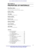
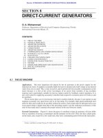
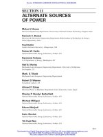
Lay, or Pitch. The axial length of one complete turn, or helix, of a wire in a stranded conductor is
sometimes termed the lay, or pitch. This is often expressed as the pitch ratio, which is the ratio of
the length of the helix to its pitch diameter (diameter of the helix at the centerline of any individual
wire or strand equals the outside diameter of the helix minus the thickness of one wire or strand). If
there are several layers, the pitch expressed as an axial length may increase with each additional
layer, but when expressed as the ratio of axial length to pitch diam-
eter of helix, it is usually the same for all layers, or nearly so. In
commercial practice, the pitch is commonly expressed as the ratio of
axial length to outside diameter of helix, but this is an arbitrary des-
ignation made for convenience of usage. The pitch angle is shown
in Fig. 4-1, where ac represents the axis of the stranded conductor
and l is the axial length of one complete turn or helix, ab is the
length of any individual wire l +∆l in one complete turn, and bc is
equal to the circumference of a circle corresponding to the pitch
diameter d of the helix. The angle bac, or , is the pitch angle, and the pitch ratio is expressed by
p ϭ l/d. There is no standard pitch ratio used by manufacturers generally, since it has been found
desirable to vary this depending on the type of service for which the conductor is intended. Applicable
lay lengths generally are included in industry specifications covering the various stranded conduc-
tors. For bare overhead conductors, a representative commercial value for pitch length is 13.5 times
the outside diameter of each layer of strands.
Direction of Lay. The direction of lay is the lateral direction in which the individual wires of a
cable run over the top of the cable as they recede from an observer looking along the axis. Right-
hand lay recedes from the observer in clockwise rotation or like a right-hand screw thread; left-hand
lay is the opposite. The outer layer of a cable is ordinarily applied with a right-hand lay for bare over-
head conductors and left-hand lay for insulated conductors, although the opposite lay can be used if
desired.
Increase in Weight Due to Stranding. Referring to Fig. 4-1, the increase in weight of the spiral
members in a cable is proportional to the increase in length
(4-15)
As a first approximation this ratio equals 1 ϩ 0.5(
2
/p
2
), and a pitch of 15.7 produces a ratio of 1.02.
This correction factor should be computed separately for each layer if the pitch p varies from layer
to layer.
Increase in Resistance Due to Stranding. If it were true that no current flows from wire to wire
through their lineal contacts, the proportional increase in the total resistance would be the same
as the proportional increase in total weight. If all the wires were in perfect and complete contact
with each other, the total resistance would decrease in the same proportion that the total weight
increases, owing to the slightly increased normal cross section of the cable as a whole. The con-
tact resistances are normally sufficient to make the actual increase in total resistance nearly as
much, proportionately, as the increase in total weight, and for practical purposes they are usually
assumed to be the same.
ϭ
Å
1 ϩ
p
2
p
2
ϭ 1 ϩ
1p
2
2 p
2
Ϫ
1
8
a
p
2
p
2
b
2
ϩ
c
l ϩ⌬l
l
ϭ sec
u ϭ 21 ϩ tan
2
u
4-14 SECTION FOUR
FIGURE 4-1 Pitch angle in con-
centric-lay cable.
Beaty_Sec04.qxd 17/7/06 8:27 PM Page 4-14
Downloaded from Digital Engineering Library @ McGraw-Hill (www.digitalengineeringlibrary.com)
Copyright © 2006 The McGraw-Hill Companies. All rights reserved.
Any use is subject to the Terms of Use as given at the website.
PROPERTIES OF MATERIALS
Decrease in Strength Due to Stranding. When a concentric-lay cable is subjected to mechanical
tension, the spiral members tend to tighten around those layers under them and thus produce inter-
nal compression, gripping the inner layers and the core. Consequently, the individual wires, taken as
a whole, do not behave as they would if they were true linear conductors acting independently.
Furthermore, the individual wires are never exactly alike in diameter or in strength or in elastic prop-
erties. For these reasons, there is ordinarily a loss of about 4% to 11% in total tensile efficiency,
depending on the number of layers. This reduction tends to increase as the pitch ratio decreases.
Actual tensile tests on cables furnish the most dependable data on their ultimate strength.
Tensile efficiency of a stranded conductor is the ratio of its breaking strength to the sum of the
tensile strengths of all its individual wires. Concentric-lay cables of 12 to 16 pitch ratio have a nor-
mal tensile efficiency of approximately 90%; rope-lay cables, approximately 80%.
Preformed Cable. This type of cable is made by preforming each individual wire (except the core)
into a spiral of such length and curvature that the wire will fit naturally into its normal position in
the cable instead of being forced into that shape under the usual tension in the stranding machine.
This method has the advantage in cable made of the stiffer grades of wire that the individual wires
do not tend to spread or untwist if the strand is cut in two without first binding the ends on each side
of the cut.
Weight. A uniform cylindrical conductor of diameter d, length l, and density ␦ has a total weight
expressed by the formula
(4-16)
The weight of any conductor is commonly expressed in pounds per unit of length, such as 1 ft, 1000 ft,
or 1 mi. The weight of stranded conductors can be calculated using Eq. (4-16), but allowance must be
made for increase in weight due to stranding. Rope-lay stranding has greater increase in weight because
of the multiple stranding operations.
Breaking Strength. The maximum load that a conductor attains when tested in tension to rupture.
Total Elongation at Rupture. When a sample of any material is tested under tension until it rup-
tures, measurement is usually made of the total elongation in a certain initial test length. In certain
kinds of testing, the initial test length has been standardized, but in every case, the total elongation
at rupture should be referred to the initial test length of the sample on which it was measured. Such
elongation is usually expressed in percentage of original unstressed length and is a general index of
the ductility of the material. Elongation is determined on solid conductors or on individual wires
before stranding; it is rarely determined on stranded conductors.
Elasticity. All materials are deformed in greater or lesser degree under application of mechanical
stress. Such deformation may be either of two kinds, known, respectively, as elastic deformation and
permanent deformation. When a material is subjected to stress and undergoes deformation but
resumes its original shape and dimensions when the stress is removed, the deformation is said to be
elastic. If the stress is so great that the material fails to resume its original dimensions when the stress
is removed, the permanent change in dimensions is termed permanent deformation or set. In general,
the stress at which appreciable permanent deformation begins is termed the working elastic limit.
Below this limit of stress the behavior of the material is said to be elastic, and in general, the defor-
mation is proportional to the stress.
Stress and Strain. The stress in a material under load, as in simple tension or compression, is
defined as the total load divided by the area of cross section normal to the direction of the load, assum-
ing the load to be uniformly distributed over this cross section. It is commonly expressed in pounds
per square inch. The strain in a material under load is defined as the total deformation measured in
W ϭ dl
pd
2
4
PROPERTIES OF MATERIALS 4-15
Beaty_Sec04.qxd 17/7/06 8:27 PM Page 4-15
Downloaded from Digital Engineering Library @ McGraw-Hill (www.digitalengineeringlibrary.com)
Copyright © 2006 The McGraw-Hill Companies. All rights reserved.
Any use is subject to the Terms of Use as given at the website.
PROPERTIES OF MATERIALS
the direction of the stress, divided by the total unstressed length in which the measured deformation
occurs, or the deformation per unit length. It is expressed as a decimal ratio or numeric.
In order to show the complete behavior of any given conductor under tension, it is customary to
make a graph in terms of loading or stress as the ordinates and elongation or strain as the abscissas.
Such graphs or curves are useful in determining the elastic limit and the yield point if the loading is
carried to the point of rupture. Graphs showing the relationship between stress and strain in a mate-
rial tested to failure are termed load-deformation or stress-strain curves.
Hooke’s law consists of the simple statement that the stress is proportional to the strain. It obvi-
ously implies a condition of perfect elasticity, which is true only for stresses less than the elastic limit.
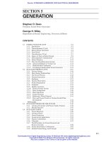
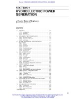
Stress-Strain Curves. A typical stress-strain diagram of hard-drawn copper wire is shown in Fig. 4-2,
which represents No. 9 AWG. The curve ae is the actual stress-strain curve; ab represents the portion
which corresponds to true elasticity, or for which Hooke’s law holds rigorously; cd is the tangent
ae which fixes the Johnson elastic limit; and the curve af represents the set, or permanent elongation
due to flow of the metal under stress, being the difference between ab and ae. A typical stress-strain
diagram of hard-drawn aluminum wire, based on data furnished by the Aluminum Company of
America, is shown in Fig. 4-3.
Modulus (or Coefficient) of Elasticity. Modulus (or coefficient) of elasticity is the ratio of internal
stress to the corresponding strain or deformation. It is a characteristic of each material, form (shape
or structure), and type of stressing. For deformations involving changes in both volume and shape,
special coefficients are used. For conductors under axial tension, the ratio of stress to strain is called
Young’s modulus.
If F is the total force or load acting uniformly on the cross section A, the stress is F/A. If this mag-
nitude of stress causes an elongation e in an original length l, the strain is e/l. Young’s modulus is
then expressed
(4-17)
If a material were capable of sustaining an elastic elongation sufficient to make e equal to l, or
such that the elongated length is double the original length, the stress required to produce this result
would equal the modulus. This modulus is very useful in computing the sags of overhead conductor
spans under loads of various kinds. It is usually expressed in pounds per square inch.
Stranding usually lowers the Young’s modulus somewhat, rope-lay stranding to a greater extent
than concentric-lay stranding. When a new cable is subjected initially to tension and the loading is
M ϭ
Fl
Ae
4-16 SECTION FOUR
FIGURE 4-2 Stress-strain curves of No. 9
AWG hard-drawn copper wire. (Watertown
Arsenal test).
FIGURE 4-3 Typical stress-strain curve of hard
drawn aluminum wire.
Beaty_Sec04.qxd 17/7/06 8:27 PM Page 4-16
Downloaded from Digital Engineering Library @ McGraw-Hill (www.digitalengineeringlibrary.com)
Copyright © 2006 The McGraw-Hill Companies. All rights reserved.
Any use is subject to the Terms of Use as given at the website.
PROPERTIES OF MATERIALS
carried up to the maximum working stress, there is an apparent elongation which is greater than the
subsequent elongation under the same loading. This is apparently due to the removal of a very slight
slackness in the individual wires, causing them to fit closely together and adjust themselves to the
conditions of tension in the strand. When a new cable is loaded to the working limit, unloaded, and
then reloaded, the value of Young’s modulus determined on initial loading may be on the order of
one-half to two-thirds of its true value on reloading. The latter figure should approach within a few
percent of the modulus determined by test on individual straight wires of the same material.
For those applications where elastic stretching under tension needs consideration, the stress-
strain curve should be determined by test, with the precaution not to prestress the cable before test
unless it will be prestressed when installed in service. Commercially used values of Young’s modu-
lus for conductors are given in Table 4-1.
PROPERTIES OF MATERIALS 4-17
TABLE 4-1 Young’s Moduli for Conductors
Young’s modulus,* lb/in
2
Conductor Final
†
Virtual initial
‡
Reference
Copper wire, hard-drawn 17.0 ⋅ 10
6
14.5 ⋅ 10
6
Copper Wire Engineering Assoc.
Copper wire, medium hard-drawn 16.0 ⋅ 10
6
14.0 ⋅ 10
6
Anaconda Wire and Cable Co.
Copper cable, hard-drawn, 3 and 12 wire 17.0 ⋅ 10
6
14.0 ⋅ 10
6
Copper Wire Engineering Assoc.
Copper cable, hard-drawn, 7 and 19 wire 17.0 ⋅ 10
6
14.5 ⋅ 10
6
Copper Wire Engineering Assoc.
Copper cable, medium hard-drawn 15.5 ⋅ 10
6
14.0 ⋅ 10
6
Anaconda Wire and Cable Co.
Bronze wire, alloy 15 14.0 ⋅ 10
6
13.0 ⋅ 10
6
Anaconda Wire and Cable Co.
Bronze wire, other alloys 16.0 ⋅ 10
6
14.0 ⋅ 10
6
Anaconda Wire and Cable Co.
Bronze cable, alloy 15 13.0 ⋅ 10
6
12.0 ⋅ 10
6
Anaconda Wire and Cable Co.
Bronze cable, other alloys 16.0 ⋅ 10
6
14.0 ⋅ 10
6
Anaconda Wire and Cable Co.
Copper-clad steel wire 24.0 ⋅ 10
6
22.0 ⋅ 10
6
Copperweld Steel Co.
Copper-clad steel cable 23.0 ⋅ 10
6
20.5 ⋅ 10
6
Copperweld Steel Co.
Copper–copper-clad steel cable, type E 19.5 ⋅ 10
6
17.0 ⋅ 10
6
Copperweld Steel Co.
Copper–copper-clad steel cable, type EK 18.5 ⋅ 10
6
16.0 ⋅ 10
6
Copperweld Steel Co.
Copper–copper-clad steel cable, type F 18.0 ⋅ 10
6
15.5 ⋅ 10
6
Copperweld Steel Co.
Copper–copper-clad steel cable, type 2A to 6A 19.0 ⋅ 10
6
16.5 ⋅ 10
6
Copper Wire Engineering Assoc.
Aluminum wire 10.0 ⋅ 10
6
Reynolds Metals Co.
Aluminum cable 9.1 ⋅ 10
6
7.3 ⋅ 10
6
Reynolds Metals Co.
Aluminum-alloy wire 10.0 ⋅ 10
6
Reynolds Metals Co.
Aluminum-alloy cable 9.1 ⋅ 10
6
7.3 ⋅ 10
6
Reynolds Metals Co.
Aluminum-steel cable, aluminum wire 7.2–9.0 ⋅ 10
6
Aluminum Co. of America
Aluminum-steel cable, steel wire 26.0–29.0 ⋅ 10
6
Aluminum Co. of America
Aluminum-clad steel wire 23.5 ⋅ 10
6
22.0 ⋅ 10
6
Copperweld Steel Co.
Aluminum-clad steel cable 23.0 ⋅ 10
6
21.5 ⋅ 10
6
Copperweld Steel Co.
Aluminum-clad steel–aluminum cable:
AWAC 5/2 13.5 ⋅ 10
6
12.0 ⋅ 10
6
Copperweld Steel Co.
AWAC 4/3 15.5 ⋅ 10
6
14.0 ⋅ 10
6
Copperweld Steel Co.
AWAC 3/4 17.5 ⋅ 10
6
16.0 ⋅ 10
6
Copperweld Steel Co.
AWAC 2/5 19.0 ⋅ 10
6
18.0 ⋅ 10
6
Copperweld Steel Co.
Galvanized-steel wire, Class A coating 28.5 ⋅ 10
6
Indiana Steel & Wire Co.
Galvanized-steel cable, Class A coating 27.0 ⋅ 10
6
Indiana Steel & Wire Co.
Note: 1 lb/in
2
ϭ 6.895 kPa.
∗
For stranded cables the moduli are usually less than for solid wire and vary with number and arrangement of strands, tightness of stranding, and
length of lay. Also, during initial application of stress, the stress-strain relation follows a curve throughout the upper part of the range of stress com-
monly used in transmission-line design.
†
Final modulus is the ratio of stress to strain (slope of the curve) obtained after fully prestressing the conductor. It is used in calculating design or
final sags and tensions.
‡
Virtual initial modulus is the ratio of stress to strain (slope of the curve) obtained during initial sustained loading of new conductor. It is used in
calculating initial or stringing sags and tensions.
Beaty_Sec04.qxd 17/7/06 8:27 PM Page 4-17
Downloaded from Digital Engineering Library @ McGraw-Hill (www.digitalengineeringlibrary.com)
Copyright © 2006 The McGraw-Hill Companies. All rights reserved.
Any use is subject to the Terms of Use as given at the website.
PROPERTIES OF MATERIALS
Young’s Modulus for ACSR. The permanent modulus of ACSR depends on the proportions of steel
and aluminum in the cable and on the distribution of stress between aluminum and steel. This latter
condition depends on temperature, tension, and previous maximum loadings. Because of the inter-
change of stress between the steel and the aluminum caused by changes of tension and temperature,
computer programs are ordinarily used for sag-tension calculations.
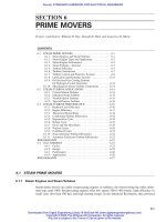
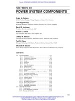
Because ACSR is a composite cable made of alu-
minum and steel wires, additional phenomena occur
which are not found in tests of cable composed of a sin-
gle material. As shown in Fig. 4-4, the part of the curve
obtained in the second stress cycle contains a compara-
tively large “foot” at its base, which is caused by the dif-
ference in extension at the elastic limits of the aluminum
and steel.
Elastic Limit. This is variously defined as the limit of
stress beyond which permanent deformation occurs or the
stress limit beyond which Hooke’s law ceases to apply or
the limit beyond which the stresses are not proportional to
the strains or the proportional limit. In some materials, the
elastic limit occurs at a point which is readily determined,
but in others it is quite difficult to determine because the
stress-strain curve deviates from a straight line but very
slightly at first, and the point of departure from true linear
relationship between stress and strain is somewhat indeterminate.
Dean J. B. Johnson of the University of Wisconsin, well-known authority on materials of con-
struction, proposed the use of an arbitrary determination referred to frequently as the Johnson defi-
nition of elastic limit. This proposal, which has been quite largely used, was that an apparent elastic
limit be employed, defined as that point on the stress-strain curve at which the rate of deformation is
50% greater than at the origin. The apparent elastic limit thus defined is a practical value, which is
suitable for engineering purposes because it involves negligible permanent elongation.
The Johnson elastic limit is that point on the stress-strain curve at which the natural tangent is
equal to 1.5 times the tangent of the angle of the straight or linear portion of the curve, with respect
to the axis of ordinates, or Y axis.
Yield Point. In many materials, a point is reached on the stress-strain diagram at which there is a
marked increase in strain or elongation without an increase in stress or load. The point at which this
occurs is termed the yield point. It is usually quite noticeable in ductile materials but may be scarcely
perceptible or possibly not present at all in certain hard-drawn materials such as hard-drawn copper.
Prestressed Conductors. In the case of some materials, especially those of considerable ductility,
which tend to show permanent elongation or “drawing” under loads just above the initial elastic
limit, it is possible to raise the working elastic limit by loading them to stresses somewhat above the
elastic limit as found on initial loading. After such loading, or prestressing, the material will behave
according to Hooke’s law at all loads less than the new elastic limit. This applies not only to many
ductile materials, such as soft or annealed copper wire, but also to cables or stranded conductors, in
which there is a slight inherent slack or looseness of the individual wires that can be removed only
under actual loading. It is sometimes the practice, when erecting such conductors for service, to pre-
stress them to the working elastic limit or safe maximum working stress and then reduce the stress
to the proper value for installation at the stringing temperature without wind or ice.
Resistance. Resistance is the property of an electric circuit or of any body that may be used as part
of an electric circuit which determines for a given current the average rate at which electrical ener-
gy is converted into heat. The term is properly applied only when the rate of conversion is propor-
tional to the square of the current and is then equal to the power conversion divided by the square of
4-18 SECTION FOUR
FIGURE 4-4 Repeated stress-strain curve,
795,000 cmil ACSR; 54 × 0.1212 aluminum
strands, 7 × 0.1212 steel strands.
Beaty_Sec04.qxd 17/7/06 8:27 PM Page 4-18
Downloaded from Digital Engineering Library @ McGraw-Hill (www.digitalengineeringlibrary.com)
Copyright © 2006 The McGraw-Hill Companies. All rights reserved.
Any use is subject to the Terms of Use as given at the website.
PROPERTIES OF MATERIALS
the current. A uniform cylindrical conductor of diameter d, length l, and volume resistivity r has a
total resistance to continuous currents expressed by the formula
(4-18)
The resistance of any conductor is commonly expressed in ohms per unit of length, such as 1 ft,
1000 ft, or 1 mi. When used for conducting alternating currents, the effective resistance may be higher
than the dc resistance defined above. In the latter case, it is a common practice to apply the proper fac-
tor, or ratio of effective ac resistance to dc resistance, sometimes termed the skin-effect resistance
ratio. This ratio may be determined by test, or it may be calculated if the necessary data are available.
Magnetic Permeability. Magnetic permeability applies to a field in which the flux is uniformly dis-
tributed over a cross section normal to its direction or to a sufficiently small cross section of a
nonuniform field so that the distribution can be assumed as substantially uniform. In the case of a
cylindrical conductor, the magnetomotive force (mmf) due to the current flowing in the conductor
varies from zero at the center or axis to a maximum at the periphery or surface of the conductor and
sets up a flux in circular paths concentric with the axis and perpendicular to it but of nonuniform dis-
tribution between the axis and the periphery. If the permeability is nonlinear with respect to the mmf,
as is usually true with magnetic materials, there is no correct single value of permeability which fits
the conditions, although an apparent or equivalent average value can be determined. In the case of
other forms of cross section, the distribution is still more complex, and the equivalent permeability
may be difficult or impossible to determine except by test.
Internal Inductance. A uniform cylindrical conductor of nonmagnetic material, or of unit perme-
ability, has a constant magnitude of internal inductance per unit length, independent of the conduc-
tor diameter. This is commonly expressed in microhenrys or millihenrys per unit of length, such as
1 ft, 1000 ft, or 1 mi. When the conductor material possesses magnetic susceptibility, and when the
magnetic permeability m is constant and therefore independent of the current strength, the internal
inductance is expressed in absolute units by the formula
(4-19)
In most cases, m is not constant but is a function of the current strength. When this is true, there
is an effective permeability, one-half of which (m/2) expresses the inductance per centimeter of
length, but this figure of permeability is virtually the ratio of the effective inductance of the conduc-
tor of susceptible material to the inductance of a conductor of material which has a permeability of
unity. When used for conducting alternating currents, the effective inductance may be less than the
inductance with direct current; this is also a direct consequence of the same skin effect which results in
an increase of effective resistance with alternating currents, but the overall effect is usually included in
the figure of effective permeability. It is usually the practice to determine the effective internal induc-
tance by test, but it may be calculated if the necessary data are available.
Skin Effect. Skin effect is a phenomenon which occurs in conductors carrying currents whose
intensity varies rapidly from instant to instant but does not occur with continuous currents. It arises
from the fact that elements or filaments of variable current at different points in the cross section of
a conductor do not encounter equal components of inductance, but the central or axial filament meets
the maximum inductance, and in general the inductance offered to other filaments of current decreases
as the distance of the filament from the axis increases, becoming a minimum at the surface or periph-
ery of the conductor. This, in turn, tends to produce unequal current density over the cross section as
a whole; the density is a minimum at the axis and a maximum at the periphery. Such distribution of
the current density produces an increase in effective resistance and a decrease in effective internal
inductance; the former is of more practical importance than the latter. In the case of large copper
L ϭ
ml
2
R ϭ
rl
pd
2
/4
PROPERTIES OF MATERIALS 4-19
Beaty_Sec04.qxd 17/7/06 8:27 PM Page 4-19
Downloaded from Digital Engineering Library @ McGraw-Hill (www.digitalengineeringlibrary.com)
Copyright © 2006 The McGraw-Hill Companies. All rights reserved.
Any use is subject to the Terms of Use as given at the website.
PROPERTIES OF MATERIALS
conductors at commercial power frequencies and in the case of most conductors at carrier and radio
frequencies, the increase in resistance should be considered.
Skin-Effect Ratios. If Rr is the effective resistance of a linear cylindrical conductor to sinusoidal
alternating current of given frequency and R is the true resistance with continuous current, then
(4-20)
where K is determined from Table 4-2 in terms of x. The value of x is given by
(4-21)
where a is the radius of the conductor in centimeters, f is the frequency in cycles per second, m is the
magnetic permeability of the conductor (here assumed to be constant), and r is the resistivity in
abohm-centimeters (abohm ϭ 10
–9
Ω).
x ϭ 2pa
Å
2fm
r
Rr ϭ KR
ohms
4-20 SECTION FOUR
TABLE 4-2 Skin-Effect Ratios
xK KЈ xK KЈ xK KЈ xK KЈ
0.0 1.00000 1.00000 2.9 1.28644 0.86012 6.6 2.60313 0.42389 17.0 6.26817 0.16614
0.1 1.00000 1.00000 3.0 1.31809 0.84517 6.8 2.67312 0.41171 18.0 6.62129 0.15694
0.2 1.00001 1.00000 3.1 1.35102 0.82975 7.0 2.74319 0.40021 19.0 6.97446 0.14870
0.3 1.00004 0.99998 3.2 1.38504 0.81397 7.2 2.81334 0.38933 20.0 7.32767 0.14128
0.4 1.00013 0.99993 3.3 1.41999 0.79794 7.4 2.88355 0.37902 21.0 7.68091 0.13456
0.5 1.00032 0.99984 3.4 1.45570 0.78175 7.6 2.95380 0.36923 22.0 8.03418 0.12846
0.6 1.00067 0.99966 3.5 1.49202 0.76550 7.8 3.02411 0.35992 23.0 8.38748 0.12288
0.7 1.00124 0.99937 3.6 1.52879 0.74929 8.0 3.09445 0.35107 24.0 8.74079 0.11777
0.8 1.00212 0.99894 3.7 1.56587 0.73320 8.2 3.16480 0.34263 25.0 9.09412 0.11307
0.9 1.00340 0.99830 3.8 1.60314 0.71729 8.4 3.23518 0.33460 26.0 9.44748 0.10872
1.0 1.00519 0.99741 3.9 1.64051 0.70165 8.6 3.30557 0.32692 28.0 10.15422 0.10096
1.1 1.00758 0.99621 4.0 1.67787 0.68632 8.8 3.37597 0.31958 30.0 10.86101 0.09424
1.2 1.01071 0.99465 4.1 1.71516 0.67135 9.0 3.44638 0.31257 32.0 11.56785 0.08835
1.3 1.01470 0.99266 4.2 1.75233 0.65677 9.2 3.51680 0.30585 34.0 12.27471 0.08316
1.4 1.01969 0.99017 4.3 1.78933 0.64262 9.4 3.58723 0.29941 36.0 12.98160 0.07854
1.5 1.02582 0.98711 4.4 1.82614 0.62890 9.6 3.65766 0.29324 38.0 13.68852 0.07441
1.6 1.03323 0.98342 4.5 1.86275 0.61563 9.8 3.72812 0.28731 40.0 14.39545 0.07069
1.7 1.04205 0.97904 4.6 1.89914 0.60281 10.0 3.79857 0.28162 42.0 15.10240 0.06733
1.8 1.05240 0.97390 4.7 1.93533 0.59044 10.5 3.97477 0.26832 44.0 15.80936 0.06427
1.9 1.06440 0.96795 4.8 1.97131 0.57852 11.0 4.15100 0.25622 46.0 16.51634 0.06148
2.0 1.07816 0.96113 4.9 2.00710 0.56703 11.5 4.32727 0.24516 48.0 17.22333 0.05892
2.1 1.09375 0.95343 5.0 2.04272 0.55597 12.0 4.50358 0.23501 50.0 17.93032 0.05656
2.2 1.11126 0.94482 5.2 2.11353 0.53506 12.5 4.67993 0.22567 60.0 21.46541 0.04713
2.3 1.13069 0.93527 5.4 2.18389 0.51566 13.0 4.85631 0.21703 70.0 25.00063 0.04040
2.4 1.15207 0.92482 5.6 2.25393 0.49764 13.5 5.03272 0.20903 80.0 28.53593 0.03535
2.5 1.17538 0.91347 5.8 2.32380 0.48086 14.0 5.20915 0.20160 90.0 32.07127 0.03142
2.6 1.20056 0.90126 6.0 2.39359 0.46521 14.5 5.38560 0.19468 100.0 35.60666 0.02828
2.7 1.22753 0.88825 6.2 2.46338 0.45056 15.0 5.56208 0.18822 ϱϱ 0
2.8 1.25620 0.87451 6.4 2.53321 0.43682 16.0 5.91509 0.17649
Beaty_Sec04.qxd 17/7/06 8:27 PM Page 4-20
Downloaded from Digital Engineering Library @ McGraw-Hill (www.digitalengineeringlibrary.com)
Copyright © 2006 The McGraw-Hill Companies. All rights reserved.
Any use is subject to the Terms of Use as given at the website.
PROPERTIES OF MATERIALS
For practical calculation, Eq. (4-21) can be written
(4-22)
where R is dc resistance at operating temperature in ohms per mile.
If Lr is the effective inductance of a linear conductor to sinusoidal alternating current of a given
frequency, then
(4-23)
where L
1
is external portion of inductance, L
2
is internal portion (due to the magnetic field within the
conductor), and KЈ is determined from Table 4-2 in terms of x. Thus, the total effective inductance
per unit length of conductor is
(4-24)
The inductance is here expressed in abhenrys per centimeter of conductor, in a linear circuit; a is the
radius of the conductor, and d is the separation between the conductor and its return conductor,
expressed in the same units.
Values of K and KЈ in terms of x are shown in Table 4-2 and Figs. 4-5 and 4-6 (see NBS Circ. 74,
pp. 309–311, for additional tables, and Sci. Paper 374).
Value of m for nonmagnetic materials (copper, aluminum, etc.) is 1; for magnetic materials, it
varies widely with composition, processing, current density, etc., and should be determined by test
in each case.
Alternating-Current Resistance. For small conductors at power frequencies, the frequency has a
negligible effect, and dc resistance values can be used. For large conductors, frequency must be taken
into account in addition to temperature effects. To do this, first calculate the dc resistance at the oper-
ating temperature, then determine the skin-effect ratio K, and finally determine the ac resistance at
operating temperature.
AC resistance for copper conductors not in close proximity can be obtained from the skin-effect
ratios given in Tables 4-2 and 4-3.
AC Resistance for Aluminum Conductors. The increase in resistance and decrease in internal
inductance of cylindrical aluminum conductors can be determined from data. It is not the same as
for copper conductors of equal diameter but is slightly less because of the higher volume resistivity
of aluminum.
Lr ϭ 2 ln
d
a
ϩ K r
m
2
Lr ϭ L
1
ϩ K r L
2
x ϭ 0.063598
Å
fm
R
PROPERTIES OF MATERIALS 4-21
FIGURE 4-5 K and KЈ for values of x from
0 to 100.
FIGURE 4-6 K and KЈ for values of x
from 0 to 10.
Beaty_Sec04.qxd 17/7/06 8:27 PM Page 4-21
Downloaded from Digital Engineering Library @ McGraw-Hill (www.digitalengineeringlibrary.com)
Copyright © 2006 The McGraw-Hill Companies. All rights reserved.
Any use is subject to the Terms of Use as given at the website.
PROPERTIES OF MATERIALS
TABLE 4-3 Skin-Effect Ratios—Copper Conductors Not in Close Proximity
Skin-effect ratio K at 60 cycles and 65°C (149°F)
Inside conductor diameter, in
0
∗
0.25 0.50 0.75 1.00 1.25 1.30 2.00
Conductor Outside Outside Outside Outside Outside Outside Outside Outside
size, Mcm diameter, diameter, diameter, diameter, diameter, diameter, diameter, diameter,
in K in K in K in K in K in K in K in K
3000 1.998 1.439 2.02 1.39 2.08 1.36 2.15 1.29 2.27 1.23 2.39 1.19 2.54 1.15 2.87 1.08
2500 1.825 1.336 1.87 1.28 1.91 1.24 2.00 1.20 2.12 1.16 2.25 1.12 2.40 1.09 2.75 1.05
2000 1.631 1.239 1.67 1.20 1.72 1.17 1.80 1.12 1.94 1.09 2.09 1.06 2.25 1.05 2.61 1.02
1500 1.412 1.145 1.45 1.12 1.52 1.09 1.63 1.06 1.75 1.04 1.91 1.03 2.07 1.02 2.47 1.01
1000 1.152 1.068 1.19 1.05 1.25 1.03 1.39 1.02 1.53 1.01 1.72 1.01
800 1.031 1.046 1.07 1.04 1.16 1.02 1.28 1.01 1.45 1.01
600 0.893 1.026 0.94 1.02 1.04 1.01
500 0.814 1.018 0.86 1.01 0.97 1.01
400 0.728 1.012 0.78 1.01
300 0.630 1.006
Note: 1 in ϭ 2.54 cm.
∗
For standard concentric-stranded conductors (i.e., inside diameter
ϭ 0).
4-22
Beaty_Sec04.qxd 17/7/06 8:27 PM Page 4-22
Downloaded from Digital Engineering Library @ McGraw-Hill (www.digitalengineeringlibrary.com)
Copyright © 2006 The McGraw-Hill Companies. All rights reserved.
Any use is subject to the Terms of Use as given at the website.
PROPERTIES OF MATERIALS
AC Resistance for ACSR. In the case of ACSR conductors, the steel core is of relatively high resis-
tivity, and therefore its conductance is usually neglected in computing the total resistance of such
strands. The effective permeability of the grade of steel employed in the core is also relatively small.
It is approximately correct to assume that such a strand is hollow and consists exclusively of its
aluminum wires; in this case, the laws of skin effect in tubular conductors will be applicable.
Conductors having a single layer of aluminum wires over the steel core have higher ac/dc ratios than
those having multiple layers of aluminum wires.
Inductive Reactance. Present practice is to consider inductive reactance as split into two compo-
nents: (1) that due to flux within a radius of 1 ft including the internal reactance within the conduc-
tor of radius r and (2) that due to flux between 1 ft radius and the equivalent conductor spacing D
s
or geometric mean distance (GMD). The fundamental inductance formula is
(4-25)
This can be rewritten
(4-26)
where the term 2 ln (D
s
/1) represents inductance due to flux between 1 ft radius and the equivalent con-
ductor spacing, and 2 ln (1/r) ϩ (m/2) represents the inductance due to flux within 1 ft radius [2 ln (1/r)
represents inductance due to flux between conductor surface and 1 ft radius, and m/2 represents inter-
nal inductance due to flux within the conductor].
By definition, geometric mean radius (GMR) of a conductor is the radius of an infinitely thin tube
having the same internal inductance as the conductor. Therefore,
(4-27)
Since inductive reactance ϭ 2fL, for practical calculation Eq. (4-27) can be written
(4-28)
In the conductor tables in this section, inductive reactance is calculated from Eq. (4-28), consid-
ering that
(4-29)
Inductive reactance for conductors using steel varies in a manner similar to ac resistance.
Capacitive Reactance. The capacitive reactance can be considered in two parts also, giving
(4-30)
In the conductor tables in this section, capacitive reactance is calculated from Eq. (4-30), it being
considered that
(4-31)
It is important to note that in capacitance calculations the conductor radius used is the actual physi-
cal radius of the conductor.
Xr ϭ x
a
r ϩ x
d
r
X ϭ
4.099
f
log
D
s
1
ϩ
4.099
f
log
1
r
M⍀/smidsconductord
X ϭ x
a
ϩ x
d
X ϭ 0.004657 f log
D
s
1
ϩ 0.004657 f log
1
GMR
⍀/smidsconductord
L ϭ 2 ln
D
s
1
ϩ 2 ln
1
GMR
L ϭ 2 ln
D
s
1
ϩ 2 ln
1
r
ϩ
m
2
L ϭ 2 ln
D
s
r
ϩ
m
2
abH/scmdsconductord
PROPERTIES OF MATERIALS 4-23
Beaty_Sec04.qxd 17/7/06 8:27 PM Page 4-23
Downloaded from Digital Engineering Library @ McGraw-Hill (www.digitalengineeringlibrary.com)
Copyright © 2006 The McGraw-Hill Companies. All rights reserved.
Any use is subject to the Terms of Use as given at the website.
PROPERTIES OF MATERIALS
Capacitive Susceptance
(4-32)
Charging Current
(4-33)
where e is voltage to neutral in kilovolts.
Bus Conductors. Bus conductors require that greater attention be given to certain physical and
electrical characteristics of the metals than is usually necessary in designing line conductors. These
characteristics are current-carrying capacity, emissivity, skin effect, expansion, and mechanical
deflection. To obtain the most satisfactory and economical designs for bus bars in power stations and
substations, where they are used extensively, consideration must be given to choice not only of mate-
rial but also of shape. Both copper and aluminum are used for bus bars, and in certain outdoor sub-
stations, steel has proved satisfactory. The most common bus bar form for carrying heavy current,
especially indoors, is flat copper bar. Bus bars in the form of angles, channels, and tubing have been
developed for heavy currents and, because of better distribution of the conducting material, make
more efficient use of the metal both electrically and mechanically. All such designs are based on the
need for proper current-carrying capacity without excess bus bar temperatures and on the necessity
for adequate mechanical strength.
Hollow (Expanded) Conductors. Hollow (expanded) conductors are used on high-voltage trans-
mission lines when, in order to reduce corona loss, it is desirable to increase the outside diameter
without increasing the area beyond that needed for maximum line economy. Not only is the initial
corona voltage considerably higher than for conventional conductors of equal cross section, but the
current-carrying capacity for a given temperature rise is also greater because of the larger surface
area available for cooling and the better disposition of the metal with respect to skin effect when car-
rying alternating currents.
Air-expanded ACSR is a conductor whose diameter has been increased by aluminum skeletal
wires between the steel core and the outer layers of aluminum strands creating air spaces. A con-
ductor having the necessary diameter to minimize corona effects on lines operating above 300 kV
will, many times, have more metal than is economical if the conductor is made conventionally.
Composite Conductors. Composite conductors are those made up of usually two different types of
wire having differing characteristics. They are generally designed for a ratio of physical and electri-
cal characteristics different from those found in homogeneous materials. Aluminum conductors, steel
reinforced (ACSR) and aluminum conductors, aluminum alloy reinforced (ACAR) are types com-
monly used in overhead transmission and distribution lines.
Cables of this type are particularly adaptable to long-span construction or other service condi-
tions requiring more than average strength combined with liberal con-
ductance. They lend themselves readily to economical, dependable
use on transmission lines, rural distribution lines, railroad electrifica-
tion, river crossings, and many kinds of special construction.
Self-damping ACSR conductors are used to limit aeolian vibration
to a safe level regardless of conductor tension or span length. They
are concentrically stranded conductors composed of two layers of
trapezoidal-shaped wires or two layers of trapezoidal-shaped wires
and one layer of round wires of 1350 (EC) alloy with a high-strength,
coated steel core. The trapezoidal wire layers are self-supporting, and
separated by gaps from adjacent layers (Fig. 4-7). Impact between
layers during aeolian vibration causes damping action.
I
C
ϭ eB ϫ 10
Ϫ3
A/smidsconductord
B ϭ
1
x
a
r ϩ x
d
r
mSsmidsconductord
4-24 SECTION FOUR
FIGURE 4-7 Self-damping
ACSR conductor.
Beaty_Sec04.qxd 17/7/06 8:27 PM Page 4-24
Downloaded from Digital Engineering Library @ McGraw-Hill (www.digitalengineeringlibrary.com)
Copyright © 2006 The McGraw-Hill Companies. All rights reserved.
Any use is subject to the Terms of Use as given at the website.
PROPERTIES OF MATERIALS
ACSR/TW is similar to self-damping ACSR in its use of trapezoidal-shaped wires, but does not
have the annular gaps between layers. ACSR/TW has a smaller diameter and smoother surface than
conventional round-wire ACSR of the same area, and thus may have reduced wind loading.
T2 conductors are fabricated by twisting two conventional conductors together with a pitch of
about 9 ft (2.7 m). Severity of wind-induced galloping when the conductor is coated with ice is
reduced because an ice profile that is uniform along the conductor length cannot form on the vari-
able profile presented by the conductor.
Steel-supported aluminum conductors (SSAC) are similar to conventional ACSR but employ an
aluminum alloy in the annealed condition. The annealed aluminum has increased electrical conduc-
tivity, and the conductor has improved sag-tension characteristics for high-temperature service.
4.1.4 Fusible Metals and Alloys
Fusible alloys having melting points in the range from about 60 to 200°C are made principally of
bismuth, cadmium, lead, and tin in various proportions. Many of these alloys have been known under
the names of their inventors (see index of alloys in International Critical Tables, vol. 2).
Fuse metals for electric fuses of the open-link enclosed and expulsion types are ordinarily made
of some low-fusible alloy; aluminum also is used to some extent. The resistance of the fuse causes
dissipation of energy, liberation of heat, and rise of temperature. Sufficient current obviously will
melt the fuse, and thus open the circuit if the resulting arc is self-extinguishing. Metals which
volatilize readily in the heat of the arc are to be preferred to those which leave a residue of globules
of hot metal. The rating of any fuse depends critically on its shape, dimensions, mounting, enclosure,
and any other factors which affect its heat-dissipating capacity.
Fusing currents of different kinds of wire were investigated by W. H. Preece, who developed the
formula
(4-34)
where I is fusing current in amperes, d is diameter of the wire in inches, and a is a constant depend-
ing on the material. He found the following values for a:
Although this formula has been used to a considerable extent in the past, it gives values that usu-
ally are erroneous in practice because it is based on the assumption that all heat loss is due to radiation.
A formula of the general type
(4-35)
can be used with accuracy if k and n are known for the particular case (material, wire size, installa-
tion conditions, etc.).
Fusing current-time for copper conductors and connections may be determined by an equation
developed by I. M. Onderdonk
(4-36)
(4-37)I ϭ A
%
logQ
T
m
Ϫ T
a
234 ϩ T
a
ϩ 1R
33S
33a
I
A
b
2
S ϭ log a
T
m
Ϫ T
a
234 ϩ T
a
ϩ 1b
I ϭ kd
n
Copper 10,244 Iron 3,148
Aluminum 7,585 Tin 1,642
Platinum 5,172 Alloy (2Pb-1Sn) 1,318
German silver 5,230 Lead 1,379
Platinoid 4,750
I ϭ ad
3/2
PROPERTIES OF MATERIALS 4-25
Beaty_Sec04.qxd 17/7/06 8:27 PM Page 4-25
Downloaded from Digital Engineering Library @ McGraw-Hill (www.digitalengineeringlibrary.com)
Copyright © 2006 The McGraw-Hill Companies. All rights reserved.
Any use is subject to the Terms of Use as given at the website.
PROPERTIES OF MATERIALS