handbook for electrical engineers hu (4)
Bạn đang xem bản rút gọn của tài liệu. Xem và tải ngay bản đầy đủ của tài liệu tại đây (4.81 MB, 114 trang )
SECTION 5
GENERATION
Stephen O. Dean
President, Fusion Power Associates
George H. Miley
Department of Nuclear Engineering, University of Illinois
CONTENTS
5.1 FOSSIL-FUELED PLANTS . . . . . . . . . . . . . . . . . . . . . . . . . . .5-2
5.1.1 Introduction . . . . . . . . . . . . . . . . . . . . . . . . . . . . . . . . . .5-2
5.1.2 Thermodynamic Cycles . . . . . . . . . . . . . . . . . . . . . . . . .5-2
5.1.3 Reheat Steam Generators . . . . . . . . . . . . . . . . . . . . . . . .5-4
5.1.4 Fossil Fuels . . . . . . . . . . . . . . . . . . . . . . . . . . . . . . . . . .5-7
5.1.5 Classification of Coal . . . . . . . . . . . . . . . . . . . . . . . . . . .5-7
5.1.6 Impact of Fuel on Boiler Design . . . . . . . . . . . . . . . . . . .5-9
5.1.7 Environmental Considerations . . . . . . . . . . . . . . . . . . .5-11
5.1.8 Fabric Filtration . . . . . . . . . . . . . . . . . . . . . . . . . . . . . .5-12
5.1.9 Flue-Gas Desulfurization Systems . . . . . . . . . . . . . . . .5-12
5.1.10 Advanced Methods of Using Coal . . . . . . . . . . . . . . .5-13
5.1.11 Fluidized-Bed Combustion . . . . . . . . . . . . . . . . . . . . .5-15
5.1.12 Circulating Fluidized-Bed Steam Generators . . . . . . .5-15
5.2 NUCLEAR POWER PLANTS . . . . . . . . . . . . . . . . . . . . . . . .5-16
5.2.1 Nuclear Energy . . . . . . . . . . . . . . . . . . . . . . . . . . . . . . .5-16
5.2.2 Mass-Energy Relationships . . . . . . . . . . . . . . . . . . . . . .5-17
5.2.3 The Fission Process . . . . . . . . . . . . . . . . . . . . . . . . . . .5-18
5.2.4 Neutron Interaction . . . . . . . . . . . . . . . . . . . . . . . . . . . .5-20
5.2.5 Radiation . . . . . . . . . . . . . . . . . . . . . . . . . . . . . . . . . . .5-21
5.2.6 Nuclear Plant Safety . . . . . . . . . . . . . . . . . . . . . . . . . . .5-23
5.2.7 Federal Regulations . . . . . . . . . . . . . . . . . . . . . . . . . . .5-23
5.2.8 Standards . . . . . . . . . . . . . . . . . . . . . . . . . . . . . . . . . . .5-23
5.2.9 Quality Assurance . . . . . . . . . . . . . . . . . . . . . . . . . . . .5-24
5.2.10 Nuclear Energy System . . . . . . . . . . . . . . . . . . . . . . .5-24
5.2.11 Plant Arrangement . . . . . . . . . . . . . . . . . . . . . . . . . . .5-26
5.2.12 Plant Operations . . . . . . . . . . . . . . . . . . . . . . . . . . . . .5-28
5.2.13 Control Systems . . . . . . . . . . . . . . . . . . . . . . . . . . . . .5-35
5.2.14 Radioactive Waste Disposal . . . . . . . . . . . . . . . . . . . .5-41
5.2.15 Prior and Present Trends in Nuclear-Fueled Plant . . . . . . . .
Development . . . . . . . . . . . . . . . . . . . . . . . . . . . . . . .5-44
Bibliography . . . . . . . . . . . . . . . . . . . . . . . . . . . . . . . . . . . . . .5-44
5.3 NUCLEAR POWER FOR THE FUTURE . . . . . . . . . . . . . . . .5-45
5.3.1 Advanced Concepts with Passive Safety Features . . . . .5-45
5.3.2 Breeder Reactors . . . . . . . . . . . . . . . . . . . . . . . . . . . . .5-47
5.4 NUCLEAR FUSION . . . . . . . . . . . . . . . . . . . . . . . . . . . . . . . .5-50
5.4.1 Fusion Reactions . . . . . . . . . . . . . . . . . . . . . . . . . . . . .5-50
5.4.2 Advanced Fuels . . . . . . . . . . . . . . . . . . . . . . . . . . . . . .5-51
5.4.3 Power Production . . . . . . . . . . . . . . . . . . . . . . . . . . . . .5-51
5.4.4 Nonelectrical Applications . . . . . . . . . . . . . . . . . . . . . .5-52
5.4.5 Plasma Confinement . . . . . . . . . . . . . . . . . . . . . . . . . . .5-52
5.4.6 Tokamaks . . . . . . . . . . . . . . . . . . . . . . . . . . . . . . . . . . .5-53
5.4.7 World Facilities for Fusion Research and . . . . . . . . . . . . . .
Reactor Concepts . . . . . . . . . . . . . . . . . . . . . . . . . . . . .5-56
5.4.8 Inertia Electrostatic Confinement . . . . . . . . . . . . . . . . . .5-82
5.4.9 Inertial Fusion Energy and Concepts . . . . . . . . . . . . . .5-83
5-1
Beaty_Sec05.qxd 18/7/06 4:14 PM Page 5-1
Downloaded from Digital Engineering Library @ McGraw-Hill (www.digitalengineeringlibrary.com)
Copyright © 2006 The McGraw-Hill Companies. All rights reserved.
Any use is subject to the Terms of Use as given at the website.
Source: STANDARD HANDBOOK FOR ELECTRICAL ENGINEERS
5-2 SECTION FIVE
5.4.10 Breeder Types . . . . . . . . . . . . . . . . . . . . . . . . . . . . . .5-103
5.4.11 Progress toward Attainment of Controlled Fusion . . .5-104
Bibliography . . . . . . . . . . . . . . . . . . . . . . . . . . . . . . . . . . . . . .5-107
5.5 INDUSTRIAL COGENERATION . . . . . . . . . . . . . . . . . . . . .5-110
5.5.1 Cogeneration Defined . . . . . . . . . . . . . . . . . . . . . . . . .5-110
5.5.2 Siting Cogeneration Plants . . . . . . . . . . . . . . . . . . . . .5-110
5.5.3 Basic Concept of Cogeneration . . . . . . . . . . . . . . . . . .5-111
5.5.4 Advantages of Cogeneration . . . . . . . . . . . . . . . . . . . .5-112
5.5.5 Where Is Cogeneration Being Used? . . . . . . . . . . . . .5-112
Bibliography . . . . . . . . . . . . . . . . . . . . . . . . . . . . . . . . . . . . .5-113
5.1 FOSSIL-FUELED PLANTS
5.1.1 Introduction
America—and much of the world—is becoming increasingly electrified. In 2005, more than half of
the electricity generated in the United States came from coal. For the foreseeable future, coal will
continue to be the dominant fuel used for electric power production. The low cost and abundance of
coal is one of the primary reasons why consumers in the United States benefit from some of the low-
est electricity rates of any free-market economy.
The key challenge to keeping coal viable as a generation fuel is to remove the environmental
objections to the use of coal in power plants. New technologies are being developed that could vir-
tually eliminate the sulfur, nitrogen, and mercury pollutants released when coal is burned. It may also
be possible to capture greenhouse gases that are emitted from coal-fired power plants and prevent
them from contributing to global warming concerns.
Research is also underway to increase the fuel efficiency of coal-fueled power plants. Today’s
plants convert only one-third of coal’s energy potential to electricity. New technologies could nearly
double efficiency levels in the next 10 to 15 years.
Natural gas is the fastest growing fuel for electricity generation. More than 90% of the power
plants to be built in the next 20 years will likely be fueled by natural gas. Natural gas is also likely
to be a primary fuel for distributed power generators—mini-power plants that could be sited close to
where the electricity is needed.
Natural gas-powered fuel cells are also being developed for future distributed generation appli-
cations. Fuel cells use hydrogen that can be extracted from natural gas, or perhaps in the future from
biomass or coal.
5.1.2 Thermodynamic Cycles
Rankine Cycle. The cornerstone of the modern steam power plant is a modification of the Carnot
cycle proposed by W. J. M. Rankine, a distinguished Scottish engineering professor of thermody-
namics and applied mechanics. The temperature-entropy and enthalpy-entropy diagrams of Fig. 5-1
illustrate the state changes for the Rankine cycle. With the exception that compression terminates
(state a) at boiling pressure rather than the boiling temperature (state á), the cycle resembles a Carnot
FIGURE 5-1 Simple Rankine cycle (without superheat): (a) temperature-entropy; (b) enthalpy-entropy
(Mollier).
Beaty_Sec05.qxd 18/7/06 4:14 PM Page 5-2
Downloaded from Digital Engineering Library @ McGraw-Hill (www.digitalengineeringlibrary.com)
Copyright © 2006 The McGraw-Hill Companies. All rights reserved.
Any use is subject to the Terms of Use as given at the website.
GENERATION
GENERATION 5-3
FIGURE 5-2 Single extraction regenerative cycle: (a) flow diagram; (b) temperature-entropy
diagram.
cycle. The triangle bounded by a-á and the line connecting to the temperature-entropy curve in
Fig. 5-1a signify the loss of cycle work because of the irreversible heating of the liquid from state a
to saturated liquid. The lower pressure at state a, compared to á, makes possible a much smaller work
of compression between d-a. For operating plants, it amounts to 1% or less of the turbine output.
This modification eliminates the two-phase vapor compression process, reduces compression
work to a negligible amount, and makes the Rankine cycle less sensitive than the Carnot cycle to the
irreversibilities bound to occur in an actual plant. As a result, when compared with a Carnot cycle
operating between the same temperature limits and with realistic component efficiencies, the
Rankine cycle has a larger network output per unit mass of fluid circulated, smaller size, and lower
cost of equipment. In addition, because of its relative insensitivity to irreversibilities, its operating
plant thermal efficiencies will exceed those of the Carnot cycle.
Regenerative Rankine Cycle. Refinements in component design soon brought power plants based on
the Rankine cycle to their peak thermal efficiencies, with further increases realized by modifying the
basic cycle. This occurred through increasing the temperature of saturated steam supplied to the turbine,
by increasing the turbine inlet temperature through constant-pressure superheat, by reducing the sink
temperature, and by reheating the working vapor after partial expansion followed by continued expan-
sion to the final sink temperature. In practice, all of these are employed with yet another important mod-
ification. The irreversibility associated with the heating of the compressed liquid to saturation by a finite
temperature difference is the primary thermodynamic cause of lower thermal efficiency for the Rankine
cycle. The regenerative cycle attempts to eliminate this irreversibility by using as heat sources other parts
of the cycle with temperatures slightly above that of the compressed liquid being heated.
This procedure of transferring heat from one part of a cycle to another in order to eliminate or reduce
external irreversibilities is called “regenerative heating,” which is basic to all regenerative cycles.
The scheme shown in Fig. 5-2 is a practical approach to regeneration. Extraction or “bleeding”
of steam at state c for use in the “open” heater avoids excessive cooling of the vapor during turbine
expansion; in the heater, liquid from the condenser increases in temperature by ⌬T. (Regenerative
cycle heaters are called “open” or “closed” depending on whether hot and cold fluids are mixed
directly to share energy or kept separate with energy exchange occurring by the use of metal coils.)
The extraction and heating substitute the finite temperature difference ⌬T for the infinitesimal dT
used in the theoretical regeneration process. This substitution, while failing to realize the full poten-
tial of regeneration, halves the temperature difference through which the condensate must be heated
in the basic Rankine cycle. Additional extractions and heaters permit a closer approximation to the
maximum efficiency of the idealized regenerative cycle, with further improvement over the simple
Rankine cycle shown in Fig. 5-1.
Reducing the temperature difference between the liquid entering the boiler and that of the satu-
rated fluid increases the cycle thermal efficiency. The price paid is a decrease in net work produced
per pound of vapor entering the turbine and an increase in the size, complexity, and initial cost of the
plant. Additional improvements in cycle performance may be realized by continuing to accept the
consequences of increasing the number of feedwater heating stages. Balancing cycle thermal effi-
ciency against plant size, complexity, and cost for production of power at minimum cost determines
the optimum number of heaters.
Beaty_Sec05.qxd 17/7/06 8:29 PM Page 5-3
Downloaded from Digital Engineering Library @ McGraw-Hill (www.digitalengineeringlibrary.com)
Copyright © 2006 The McGraw-Hill Companies. All rights reserved.
Any use is subject to the Terms of Use as given at the website.
GENERATION
5-4 SECTION FIVE
Reheat Cycle. The use of superheat offers a simple way to improve the thermal efficiency of the
basic Rankine cycle and reduce vapor moisture content to acceptable levels in the low-pressure
stages of the turbine. But with continued increase of higher temperatures and pressures to achieve
better cycle efficiency, in some situations available superheat temperatures are insufficient to prevent
excessive moisture from forming in the low-pressure turbine stages.
The solution to this problem is to interrupt the expansion process, remove the vapor for reheat at
constant pressure, and return it to the turbine for continued expansion to condenser pressure. The
thermodynamic cycle using this modification of the Rankine cycle is called the “reheat cycle.”
Reheating may be carried out in a section of the boiler supplying primary steam, in a separately fired
heat exchanger, or in a steam-to-steam heat exchanger. Most present-day utility units combine super-
heater and reheater in the same boiler.
Usual central-station practice combines both regenerative and reheat modifications to the basic
Rankine cycle. For large installations, reheat makes possible an improvement of approximately 5%
in thermal efficiency and substantially reduces the heat rejected to the condenser cooling water. The
operating characteristics and economics of modern plants justify the installation of only one stage of
reheat except for units operating at supercritical pressure.
Figure 5-3 shows a flow diagram for a 600-MW fossil-fueled reheat cycle designed for initial tur-
bine conditions of 2520-lb/in
2
(gage) and 1000°F steam. Six feedwater heaters are supplied by
exhaust steam from the high-pressure turbine and extraction steam from the intermediate and low-
pressure turbines. Except for the deaerating heater (third), all heaters shown are closed heaters. Three
pumps are shown: (1) the condensate pump, which pumps the condensate through oil and hydrogen
gas coolers, vent condenser, air ejector, first and second heaters, and deaerating heater; (2) the con-
densate booster pump, which pumps the condensate through fourth and fifth heaters; and (3) the
boiler feed pump, which pumps the condensate through the sixth heater to the economizer and boiler.
The mass flows noted on the diagram are in pounds per hour at the prescribed conditions for full-
load operation.
5.1.3 Reheat Steam Generators
The boiler designer must proportion heat-absorbing and heat-recovery surfaces to make best use of
the heat released by the fuel. Waterwalls, superheaters, and reheaters are exposed to convection and
radiant heat, whereas convection heat transfer predominates in air heaters and economizers.
The relative amounts of such surfaces vary with the size and operating conditions of the boiler.
A small low-pressure heating plant with no heat-recovery equipment has quite a different arrange-
ment from a large high-pressure unit operating on a reheat regenerative cycle and incorporating heat-
recovery equipment.
Factors Influencing Boiler Design. In addition to the basics of unit size, steam pressure, and
steam temperature, the designer must consider other factors that influence the overall design of the
steam generator.
Fuels. Coal, although the most common fuel, is also the most difficult to burn. The ash in coal
consists of a number of objectionable chemical elements and compounds. The high percentage of
ash that can occur in coal has a serious effect on furnace performance.
At the high temperatures resulting from the burning of fuel in the furnace, fractions of ash can
become partially fused and sticky. Depending on the quantity and fusion temperature, the partially
fused ash may adhere to surfaces contacted by the ash-containing combustion gases, causing objec-
tionable buildup of slag on or bridging between tubes. Chemicals in the ash may attack materials
such as the alloy steel used in superheaters and reheaters.
In addition to the deposits in the high-temperature sections of the unit, the air heater (the coolest
part) may be subject to corrosion and plugging of gas passages from sulfur compounds in the fuel
acting in combination with moisture present in the flue gas.
Furnace. Heat generated in the combustion process appears as furnace radiation and sensible
heat in the products of combustion. Water circulating through tubes that form the furnace wall lin-
ing absorbs as much as 50% of this heat, which, in turn, generates steam by the evaporation of part
of the circulated water.
Beaty_Sec05.qxd 17/7/06 8:29 PM Page 5-4
Downloaded from Digital Engineering Library @ McGraw-Hill (www.digitalengineeringlibrary.com)
Copyright © 2006 The McGraw-Hill Companies. All rights reserved.
Any use is subject to the Terms of Use as given at the website.
GENERATION
GENERATION 5-5
FIGURE 5-3 Reheat regenerative cycle, 600-MW subcritical-pressure fossil-fuel power plant.
Furnace design must consider water heating and steam generation in the wall tubes as well as the
processes of combustion. Practically, all large modern boilers have walls comprising water-cooled
tubes to form complete metal coverage of the furnace enclosure. Similarly, areas outside the furnace
which form enclosures for sections of superheaters, reheaters, and economizers also use either water-
or steam-cooled tube surfaces. Present practice is to use tube arrangements and configurations which
permit practically complete elimination of refractories in all areas that are exposed to high-temperature
gases.
Waterwalls usually consist of vertical tubes arranged in tangent or approximately so, connected
at top and bottom to headers. These tubes receive their water supply from the boiler drum by means
of downcomer tubes connected between the bottom of the drum and the lower headers. The steam,
Beaty_Sec05.qxd 17/7/06 8:29 PM Page 5-5
Downloaded from Digital Engineering Library @ McGraw-Hill (www.digitalengineeringlibrary.com)
Copyright © 2006 The McGraw-Hill Companies. All rights reserved.
Any use is subject to the Terms of Use as given at the website.
GENERATION
5-6 SECTION FIVE
FIGURE 5-4 Arrangement of superheater, reheater, and economizer of a large coal-fired steam generator.
along with a substantial quantity of water, is discharged from the top of the waterwall tubes into the
upper waterwall headers and then passes through riser tubes to the boiler drum. Here the steam is
separated from the water, which together with the incoming feedwater is returned to the waterwalls
through the downcomers.
Tube diameter and thickness are of concern from the standpoints of circulation and metal tem-
peratures. Thermosyphonic (also called thermal or natural) circulation boilers generally use larger-
diameter tubes than positive (pumped) circulation or once-through boilers. This practice is dictated
largely by the need for more liberal flow area to provide the lower velocities necessary with the lim-
ited head available. The use of small-diameter tubes is an advantage in high-pressure boilers because
the lesser tube thicknesses required result in lower outside tube-metal temperatures. Such small-
diameter tubes are used in recirculation boilers in which pumps provide an adequate head for circu-
lation and maintain the desired velocities.
Superheaters and Reheaters. The function of a superheater is to raise the boiler steam temperature
above the saturated temperature level. As steam enters the superheater in an essentially dry condition,
further absorption of heat sensibly increases the steam temperature.
The reheater receives superheated steam which has partly expanded through the turbine. As described
earlier, the role of the reheater in the boiler is to re-superheat this steam to a desired temperature.
Superheater and reheater design depends on the specific duty to be performed. For relatively low
final outlet temperatures, superheaters solely of the convection type are generally used. For higher final
temperatures, surface requirements are larger and, of necessity, superheater elements are located in very
high gas-temperature zones. Wide-spaced platens or panels, or wall-type superheaters or reheaters of
the radiant type, can then be used. Figure 5-4 shows an arrangement of such platen and panel surfaces.
A relatively small number of panels are located on horizontal centers of 5 to 8 ft to permit substantial
radiant heat absorption. Platen sections, on 14- to 28-in centers, are placed downstream of the panel
elements; such spacing provides high heat absorption by both radiation and convection.
Economizers. Economizers help to improve boiler efficiency by extracting heat from flue gases
discharged from the final superheater section of a radiant/reheat unit (or the evaporative bank of an
industrial boiler). In the economizer, heat is transferred to the feedwater, which enters at a tempera-
ture appreciably lower than that of saturated steam. Generally, economizers are arranged for down-
ward flow of gas and upward flow of water.
Beaty_Sec05.qxd 17/7/06 8:29 PM Page 5-6
Downloaded from Digital Engineering Library @ McGraw-Hill (www.digitalengineeringlibrary.com)
Copyright © 2006 The McGraw-Hill Companies. All rights reserved.
Any use is subject to the Terms of Use as given at the website.
GENERATION
GENERATION 5-7
Water enters from a lower header and flows through horizontal tubing constituting the heating
surface. Return bends at the ends of the tubing provide continuous tube elements, whose upper ends
connect to an outlet header that is in turn connected to the boiler drum by means of tubes or large
pipes.
As shown in Fig. 5-4, economizers of a typical utility-type boiler are located in the same pass as
the primary or horizontal sections of the superheater, or superheater and reheater, depending on the
arrangement of the surface. Tubing forming the heating surface is generally low-carbon steel. Because
steel is subject to corrosion in the presence of even extremely low concentrations of oxygen, it is nec-
essary to provide water that is practically 100% oxygen free. In central stations and other large plants,
it is a common practice to use deaerators for oxygen removal.
Air Heaters. Steam-generator air heaters have two important and concomitant functions: they
cool the gases before they pass to the atmosphere, thereby increasing fuel-firing efficiency; at the
same time, they raise the temperature of the incoming air of combustion. Depending on the pressure
and temperature cycle, the type of fuel, and the type of boiler involved, one of the two functions will
have prime importance.
For instance, in a low-pressure gas- or oil-fired industrial or marine boiler, combustion-gas tem-
perature can be lowered in several ways—by a boiler bank, by an economizer, or by an air heater.
Here, an air heater has principally a gas-cooling function, as no preheating is required to burn the oil
or gas. If the boiler is a high-pressure reheat unit burning a high-moisture subbituminous or lignitic
coal, high preheated-air temperatures are needed to evaporate the moisture in the coal before igni-
tion can take place. Here, the air-heating function becomes primary. Without exception, then, large
pulverized-coal boilers either for industry or electric power generation use air heaters to reduce the
temperature of the combustion products from the 600 to 800°F level to final exit-gas temperatures
of 275 to 350°F. In these units, the combination air is heated from about 80°F to between 500 and
750°F, depending on coal calorific value and moisture content.
In theory, only the primary air must be heated; that is, air used to actually dry the coal in the pul-
verizers. Ignited fuel can burn without preheating the secondary and tertiary air. However, there is
considerable advantage to the furnace heat-transfer process from heating all the combustion air; it
increases the rate of burning and helps raise adiabatic temperature.
5.1.4 Fossil Fuels
Fossil fuels used for steam generation in utility and industrial power plants may be classified into
solid, liquid, and gaseous fuels. Each fuel may be further classified as a natural, manufactured, or
by-product fuel. Not mutually exclusive, these classifications necessarily overlap in some areas.
Obvious examples of natural fuels are coal, crude oil, and natural gas.
Of all the fossil fuels used for steam generation in electric-utility and industrial power plants
today, coal is the most important. It is widely available throughout much of the world, and the quan-
tity and quality of coal reserves are better known than those of other fuels.
5.1.5 Classification of Coal
Coals are grouped according to rank. For the purposes of the power-plant operator, there are several
suitable ranks of coal:
Anthracite
Bituminous
Subbituminous
Lignite
The following description of coals by rank gives some of their physical characteristics.
Anthracite. Hard and very brittle, anthracite is dense, shiny black, and homogeneous with no marks
or layers. Unlike the lower-rank coals, it has a high percentage of fixed carbon and a low percentage of
Beaty_Sec05.qxd 17/7/06 8:29 PM Page 5-7
Downloaded from Digital Engineering Library @ McGraw-Hill (www.digitalengineeringlibrary.com)
Copyright © 2006 The McGraw-Hill Companies. All rights reserved.
Any use is subject to the Terms of Use as given at the website.
GENERATION
5-8 SECTION FIVE
TABLE 5-1 Classification of Coals of Rank
∗
Fixed carbon Volatile matter Calorific value limits,
limits, % limits, % Btu/lb (moist,
†
(dry, mineral- (dry, mineral- mineral-matter-
matter-free basis) matter-free basis) free basis)
Equal to or Less Equal to or Less Equal to or Less Agglomerating
Class and group greater than than greater than than greater than than character
Anthracitic
Metaanthracite 98 2 Nonagglomerating
Anthracite 92 98 2 8
Semianthracite
‡
86 92 8 14
Bituminous
Low-volatile
bituminous coal 78 86 14 22
Medium-volatile
bituminous coal 69 78 22 31
High-volatile Commonly
A bituminous coal 69 31 14,000
§
glomerating
¶
High-volatile
B bituminous coal 13,000
§
14,000
High-volatile
C bituminous coal 11,500 13,000
10,500 11,500 Agglomerating
Subbituminous
Subbituminous
A coal 10,500 11,500 Nonagglomerating
Subbituminous
B coal 9,500 10,500
Subbituminous
C coal 8,300 9,500
Lignitic
Lignite A 6,300 8,300
Lignite B 6,300
Note: 1 Btu/lb ϭ 2326 J/kg.
∗
This classification does not include a few coals, principally nonbanded varieties, which have unusual physical and chemical properties and which
come within the limits of fixed carbon or calorific value of the high-volatile bituminous and subbituminous ranks. All of these coals either contain less
than 48% dry, mineral-matter-free fixed carbon or have more than 15,500 moist, mineral-matter-free Btu per pound.
†
Moist refers to coal containing its natural inherent moisture but not including visible water on the surface of the coal.
‡
If agglomerating, classify in low-volatile group of the bituminous class.
§
Coals having 69% or more fixed carbon on the dry, mineral-matter-free basis shall be classified by fixed carbon, regardless of calorific value.
¶
It is recognized that there may be nonagglomerating varieties in these groups of the bituminous class, and there are notable exceptions in the high-
volatile C bituminous group.
Source: ASTM Standards D388, Classification of Coals by Rank.
volatile matter. Anthracites include a variety of slow-burning fuels merging into graphite at one end and
into bituminous coal at the other. They are the hardest coals on the market, consisting almost entirely
of fixed carbon, with the little volatile matter present in them chiefly as methane, CH
4
. Anthracite is
usually graded into small sizes before being burned on stokers. The “metaanthracites” burn so slowly
as to require mixing with other coals, while the “semianthracites,” which have more volatile matter, are
burned with relative ease if properly fired. Most anthracites have a lower heating value than the highest-
grade bituminous coals. Anthracite is used principally for heating homes and in gas production.
Some semianthracites are dense, but softer than anthracite, shiny gray, and somewhat granular in
structure. The grains have a tendency to break off in handling the lump, and produce a coarse, sand-
like slack. Other semianthracites are dark gray and distinctly granular. The grains break off easily in
Beaty_Sec05.qxd 17/7/06 8:29 PM Page 5-8
Downloaded from Digital Engineering Library @ McGraw-Hill (www.digitalengineeringlibrary.com)
Copyright © 2006 The McGraw-Hill Companies. All rights reserved.
Any use is subject to the Terms of Use as given at the website.
GENERATION
GENERATION 5-9
handling and produce a coarse slack. The granular structure has been produced by small vertical
cracks in horizontal layers of comparatively pure coal separated by very thin partings. The cracks are
the result of heavy downward pressure, and probably shrinkage of the pure coal because of a drop in
temperature.
Bituminous. By far the largest group, bituminous coals derive their name from the fact that on
being heated they are often reduced to a cohesive, binding, sticky mass. Their carbon content is less
than that of anthracites, but they have more volatile matter. The character of their volatile matter is
more complex than that of anthracites, and they are higher in calorific value. They burn easily, espe-
cially in pulverized form, and their high volatile content makes them good for producing gas. Their
binding nature enables them to be used in the manufacture of coke, while the nitrogen in them is uti-
lized in processing ammonia.
The low-volatile bituminous coals are grayish-black and distinctly granular in structure. The
grain breaks off very easily, and handling reduces the coal to slack. Any lumps that remain are held
together by thin partings. Because the grains consist of comparatively pure coal, the slack is usually
lower in ash content than are the lumps.
Medium-volatile bituminous coals are the transition from high-volatile to low-volatile coal and, as
such, have the characteristics of both. Many have a granular structure, are soft, and crumble easily. Some
are homogeneous with very faint indications of grains or layers. Others are of more distinct laminar
structure, are hard, and stand handling well.
High-volatile A bituminous coals are mostly homogeneous with no indication of grains, but some
show distinct layers. They are hard and stand handling with little breakage. The moisture, ash, and
sulfur contents are low, and the heating value is high.
High-volatile B bituminous coals are of distinct laminar structure; the layers of black, shiny coal
alternate with dull, charcoal-like layers. They are hard and stand handling well. Breakage occurs
generally at right angles and parallel to the layers, so that the lumps generally have a cubical shape.
High-volatile C bituminous coals are of distinct laminar structure, are hard, and stand handling
well. They generally have high moisture, ash, and sulfur contents and are considered to be free-burning
coals.
Subbituminous. These coals are brownish black or black. Most are homogeneous with smooth
surfaces, and with no indication of layers. They have high moisture content, as much as 15% to 30%,
although appearing dry. When exposed to air they lose part of the moisture and crack with an audible
noise. On long exposure to air, they disintegrate. They are free-burning, entirely noncoking, coals.
Lignite. Lignites are brown and of a laminar structure in which the remnants of woody fibers
may be quite apparent. The word lignite comes from the Latin word lignum meaning wood. Their
origin is mostly from plants rich in resin, so they are high in volatile matter. Freshly mined lignite is
tough, although not hard, and it requires a heavy blow with a hammer to break the large lumps. But
on exposure to air, it loses moisture rapidly and disintegrates. Even when it appears quite dry, the
moisture content may be as high as 30%. Owing to the high moisture and low heating value, it is not
economical to transport it long distances.
Unconsolidated lignite (B in Table 5-1) is also known as “brown coal.” Brown coals are generally
found close to the surface, contain more than 45% moisture, and are readily won by strip mining.
5.1.6 Impact of Fuel on Boiler Design
The most important item to consider when designing a utility or large industrial steam generator is
the fuel the unit will burn. The furnace size, the equipment to prepare and burn the fuel, the amount
of heating surface and its placement, the type and size of heat-recovery equipment, and the flue-gas-
treatment devices are all fuel dependent.
The major differences among those boilers that burn coal or oil or natural gas result from the ash
in the products of combustion. Firing oil in a furnace results in relatively small amounts of ash; there
is no ash from natural gas. For the same output, because of the ash, coal-burning boilers must have
larger furnaces and the velocities of the combustion gases in the convection passes must be lower. In
addition, coal-burning boilers need ash-handling and particulate-cleanup equipment that costs a great
deal and requires considerable space.
Beaty_Sec05.qxd 17/7/06 8:29 PM Page 5-9
Downloaded from Digital Engineering Library @ McGraw-Hill (www.digitalengineeringlibrary.com)
Copyright © 2006 The McGraw-Hill Companies. All rights reserved.
Any use is subject to the Terms of Use as given at the website.
GENERATION
5-10 SECTION FIVE
TABLE 5-2 Representative Coal Analyses
Medium-volume High-volume Subbituminous Low-sodium Medium-sodium High-sodium
bituminous bituminous C lignite lignite lignite
Total H
2
O, % 5.0 15.4 30.0 31.0 30.0 39.6
Ash, % 10.3 15.0 5.8 10.4 28.4 6.3
VM, % 31.6 33.1 32.6 31.7 23.2 27.5
FC, % 53.1 36.5 36.6 26.9 18.4 26.6
Btu/lb, as fired 13,240 10,500 8,125 7,590 5,000 6,523
Btu/lb, MAF 15,640 15,100 12,650 12,940 12,020 12,050
Fusion (reducing), °F
Initial def. 2,170 1,990 2,200 2,075 2,120 2,027
Softening 2,250 2,120 2,250 2,200 2,380 2,089
Fluid 2,440 2,290 2,290 2,310 2,700 2,203
Ash analysis, %
SiO
2
40.0 46.4 29.5 46.1 62.9 23.1
Al
2
O
3
24.0 16.2 16.0 15.2 17.5 11.3
Fe
2
O
3
16.8 20.0 4.1 3.7 2.8 8.5
CaO 5.8 7.1 26.5 16.6 4.8 23.8
MgO 2.0 0.8 4.2 3.2 0.7 5.9
Na
2
O 0.8 0.7 1.4 0.4 3.1 7.4
K
2
O 2.4 1.5 0.5 0.6 2.0 0.7
TiO
2
1.3 1.0 1.3 1.2 0.8 0.5
P
2
O
5
0.1 0.1 1.1 0.1 0.1 0.2
SO
3
5.3 6.0 14.8 12.7 4.6 17.7
Sulfur, % 1.8 3.2 0.3 0.6 1.7 0.8
Lb H
2
O/million Btu 3.8 14.7 36.9 40.8 60.0 60.7
Lb ash/million Btu 7.8 14.3 7.1 13.7 56.8 9.7
Fuel-fired,
∗
1000 lb/h 405 520 705 750 1,175 900
Note: 1 Btu/lb ϭ 2326 J/kg; t
°C
ϭ (t
°F
Ϫ 32)/1.8; 1 lb ϭ 0.4536 kg; 1 Btu ϭ 1055 J.
∗
Constant heat output, nominal 600-MW unit, adjusted for efficiency.
Table 5-2 lists the variation in calorific values and moisture contents of several coals, and the mass
of fuel that must be handled and fired to generate the same electrical-power output. These values are
important because the quantity of fuel required helps determine the size of the coal-storage yard, as
well as the handling, crushing, and pulverizing equipment for the various coals.
Furnace Sizing. The most important step in coal-fired unit design is to properly size the furnace.
Furnace size has a first-order influence on the size of the structural-steel framing, the boiler build-
ing and its foundations, as well as on the sootblowers, platforms, stairways, steam piping, and duct
work. The fuel-ash properties that are particularly important when designing and establishing the
size of coal-fired furnaces include
The ash fusibility temperatures (both in terms of their absolute values and the spread or differ-
ence between initial deformation temperature and fluid temperature)
The ratio of basic to acidic ash constituents
The iron/calcium ratio
The fuel-ash content in terms of pounds of ash per million British thermal units
The ash friability
These characteristics and others translate into the furnace sizes in Fig. 5-5, which are based on the
six coal ranks shown in Table 5-2. This size comparison illustrates the philosophy of increasing the
furnace plan area, volume, and the fuel burnout zone (the distance from the top fuel nozzle to the
furnace arch), as lower-grade coals with poorer ash characteristics are fired.
Beaty_Sec05.qxd 17/7/06 8:29 PM Page 5-10
Downloaded from Digital Engineering Library @ McGraw-Hill (www.digitalengineeringlibrary.com)
Copyright © 2006 The McGraw-Hill Companies. All rights reserved.
Any use is subject to the Terms of Use as given at the website.
GENERATION
GENERATION 5-11
FIGURE 5-5 Effect of coal rank on furnace sizing (constant heat output).
Figure 5-5 is a simplified characterization of actual furnaces built to burn the fuels listed in Table 5-2.
Wide variations exist in fuel properties within coal ranks, as well as within several subclassifications
(e.g., subbituminous A, B, C), each of which may require a different size furnace.
Among the most important design criteria in large pulverized-fuel furnaces are net heat input in
British thermal units per hour per square foot of furnace plan area (NHI/PA) and the vertical distance
from the top fuel nozzle to the furnace arch. Furnace dimensions must be adequate to establish the
necessary furnace retention time to properly burn the fuel as well as to cool the gaseous combustion
products. This is to ensure that the gas temperature at the entrance to the closely spaced convection
surface is well below the ash-softening temperature of the lowest-quality coal burned. Heat-absorption
characteristics of the walls are maintained using properly placed wall blowers to control the furnace
outlet gas temperature by removing ash deposited on the furnace walls below the furnace outlet
plane.
5.1.7 Environmental Considerations
Concerns for the control of air quality have probably had the largest single impact on power plant
site selection, design, operation, and cost. The three classes of emissions which are of major concern
are nitrogen oxides, sulfur oxides, and particulate matter.
Nitrogen Oxides. In the United States, nitrogen oxides can be controlled within federal, state, and
local regulatory limits by in-furnace and postcombustion techniques. With respect to firing systems,
each steam-generator manufacturer has developed specific design concepts for reducing nitrogen
oxides. The common characteristics of all of these designs, however, included a careful regulation of
the fuel/air ratio in the firing zone where the major fraction of the fuel nitrogen compounds are lib-
erated and control of the heat-liberation pattern in the furnace. Postcombustion reduction methods
utilizing reagents with or without catalysts are somewhat similar in concept among the steam-
generator suppliers.
Beaty_Sec05.qxd 17/7/06 8:29 PM Page 5-11
Downloaded from Digital Engineering Library @ McGraw-Hill (www.digitalengineeringlibrary.com)
Copyright © 2006 The McGraw-Hill Companies. All rights reserved.
Any use is subject to the Terms of Use as given at the website.
GENERATION
5-12 SECTION FIVE
Particulate Control. The traditional particulate control device in power plant applications has been
the electrostatic precipitator. In recent years, fabric filters (also called “baghouses”) have become
increasingly popular.
In electrostatic precipitation, suspended particles in the gas are electrically charged, then driven
to collecting electrodes by an electrical field; the electrodes are rapped to cause the particles to drop
into collecting hoppers. This process differs from mechanical or filtering processes in which forces
are exerted directly on the particulates rather than the gas as a whole. Effective separation of parti-
cles can be achieved with lower power expenditure, with negligible draft loss, and with little or no
effect on the composition of the gas.
The principle of electrostatic precipitation is relatively simple. The process applies an electrosta-
tic charge to dust particles with a corona discharge and passes them through an electric field where
the particles are attracted to a collecting surface. The basic elements of a precipitator include a source
of unidirectional voltage, corona or discharge electrodes, collecting electrodes, and a means of
removing the collected matter.
Single-stage (Cottrell-type) precipitators combine the ionizing and collecting step. In the more
common plate type, the electrodes are suspended between plates on insulators connected to a high-
voltage source. A voltage differential created between the discharge and collecting electrodes devel-
ops a strong electric field between them. The flue gas is passed through the field and a unipolar
discharge of gas ions, from the discharge electrode, is attached to the particulate matter.
5.1.8 Fabric Filtration
Fabric filters, or baghouses, have a long history of applications in both dry and wet filtration
processes to recover chemicals or control stack emissions. Available materials limited early bag-
house installations to temperatures below 250°F, and air dilution was frequently used ahead of the
baghouse. In addition, the chemical-resistance characteristics of the bags also curtailed fabric filtra-
tion. These two limitations retarded its development for many years, particularly as available pre-
cipitator equipment met the existing regulations.
Serious consideration of this technology began after 1970; interest heightened as installations on
large coal-fired boilers demonstrated good operating characteristics and high particulate-removal
efficiencies.
5.1.9 Flue-Gas Desulfurization Systems
Flue-gas desulfurization (FGD) began in England in 1935. The technology remained dormant until the
mid-1960s when it became active primarily in the United States and Japan. Since then, over 50 FGD
processes have been developed, differing in the chemical reagents and the resultant end products.
The most common FGD system is a lime/limestone wet scrubber. After the flue gas has been
treated in the precipitation (or baghouse), it passes through the induced fans and enters the SO
2
scrubber. If the required SO
2
removal efficiency is less than 85%, a fraction of the flue gas can be
treated while bypassing the rest to mix with and reheat the saturated flue gas leaving the scrubber.
For higher-sulfur fuels requiring SO
2
removal efficiencies of 90% or greater, the entire flue-gas
stream must be treated. Upon leaving the SO
2
absorption section, the flue gas is passed through
entrainment separators to remove any slurry droplets mixed with the gas. The saturated flue gas is
then reheated approximately 25 to 50°F above the water dewpoint before it is vented to the stack.
For low- to medium-sulfur fuels, an alternate scrubbing technology is dry scrubbing. This process
minimizes water consumption and eliminates the requirement for flue-gas reheating but requires
more expensive additives than the wet limestone systems.
The typical dry SO
2
absorber is a cocurrent classifying spray dryer. Flue gas enters the top of the
absorber through inlet assemblies containing swirl vanes. The absorbent is injected pneumatically
into the center of each swirler assembly by ultrasonic atomizing nozzles that require an air pressure
of about 60 lb/in
2
(gage). Slurry feed pressures are 10 to 15 lb/in
2
(gage). The compressed air induces
Beaty_Sec05.qxd 17/7/06 8:29 PM Page 5-12
Downloaded from Digital Engineering Library @ McGraw-Hill (www.digitalengineeringlibrary.com)
Copyright © 2006 The McGraw-Hill Companies. All rights reserved.
Any use is subject to the Terms of Use as given at the website.
GENERATION
GENERATION 5-13
primary dispersion of the absorbent slurry by mechanical shear forces produced by the two fluid
streams. Final dispersion is accomplished by shattering the droplets with ultrasonic energy produced
by the compressed air used with a proprietary nozzle design. Then ultrasonic nozzles generate
extremely fine droplets, which have diameters that range from 10 to 50 m, as shown by photo-
graphic studies.
The flue-gas outlet design requires that effluent gases make a 180° turn before leaving the
absorber. Besides eliminating product accumulation in the outlet duct, the abrupt directional change
also allows the larger particles to drop out in the absorber product hopper. This design curtails the
particulate loading to the fabric filter. Consequently, the number of cleaning cycles as well as abra-
sion of the filter medium are reduced.
As compared with ordinary fly-ash collection applications, fabric filters together with dry scrub-
bing offer a broader choice of design options. In conventional fly-ash collection applications, the fab-
ric filter experiences flue-gas temperatures about 100 to 150°F higher than encountered in dry
scrubbing. Filter media unsuitable at the higher temperatures can be used when the fabric filter fol-
lows a dry absorber. In particular, acrylic fibers become attractive because of their strength and flex
characteristics, as well as their ability to support more vigorous cleaning methods like mechanical
shaking.
5.1.10 Advanced Methods of Using Coal
Coal, which is the most abundant and economically stable fossil fuel in the United States, continues
to grow in use while under pressure to meet the most stringent federal and local emissions require-
ments. This trend has added to the cost and complexity of coal combustion technologies.
Emission-control methods that facilitate the use of coal in power plants can be classified as
Precombustion processes
In situ combustion processes
Postcombustion processes
Precombustion processes include methods to clean the coal of sulfur-bearing compounds by wet
separation, coal gasification, and coal liquefaction techniques. Coal gasification involves the partial
oxidation of coal to produce a clean gas or by production of a “clean fuel” through coal liquefaction.
Sulfur and ash are removed in these processes. The use of coal to produce a gas is not a new idea; it
has been used to produce “town gas” for over 200 years. But its use in the United States had almost
disappeared by 1930, because natural gas was abundant and low in cost. Concerns about the availabil-
ity and economic stability of gas supplies, along with environmental trends, have renewed interest in
coal gasification to produce substitute natural gas (SNG) and low- and medium-heat-content (LBTU
and MBTU) gas for chemical feedstock or power plant fuel. Coal gasification in the combined-cycle
mode has been well established as a viable technology for producing power with very low emissions
both in the United States and Europe. New plants are using technologies such as high-temperature gas
turbines, hot-gas cleanup to remove 99% of the sulfur (H
2
S), and higher-pressure combined steam
cycles to achieve overall efficiencies of greater than 40%. New integrated gasification combined-cycle
(IGCC) plants of as much as 250 MWe are available. IGCC technology produces very low emissions
per kilowatt of power and is therefore very attractive for the production of power. Likewise, coal liq-
uefaction is not a new technology, but is only in limited commercial use in the United States. South
Africa is the largest producer of synthetic liquid fuels from coal. Large-scale production of synthetic
liquid fuels from coal began in 1910 in Germany with the Fischer-Tropsch process, which is used to
produce a variety of fuels.
In fluidized-bed combustion, an in situ combustion-emission-control process, 90% to 95% of the
SO
2
is captured during combustion by a sorbent (limestone). In this process, the NO
x
production is low
because of the low temperature at which the combustion reaction takes place. NO
x
levels well fired
below 0.25 lb/MBtu have been achieved with certain coals. Fluidized-bed combustion was developed
in the 1950s and is now available for electric power plants of up to 300-MWe size. The technology has
Beaty_Sec05.qxd 17/7/06 8:29 PM Page 5-13
Downloaded from Digital Engineering Library @ McGraw-Hill (www.digitalengineeringlibrary.com)
Copyright © 2006 The McGraw-Hill Companies. All rights reserved.
Any use is subject to the Terms of Use as given at the website.
GENERATION
5-14 SECTION FIVE
FIGURE 5-6 Integrated combined-cycle power plant.
three distinct types of units: bubbling bed, hybrid velocity, and circulating fluidized bed (CFB). CFB
technology is the most popular fluidized-bed process and has evolved as a low-emission technology
with excellent fuel flexibility for the production of power. Bubbling and hybrid-velocity fluidized-bed
technologies have demonstrated low emissions while burning low-rank coals, waste fuels such as
petroleum coke, and renewable fuel such as wood and peat. Hybrid-velocity fluidized-bed combus-
tion can be readily retrofit to many older boilers that need pollution-control technology. Pressurized
fluidized-bed combustion is used to achieve low sulfur and NO
x
emissions of fluidized-bed com-
bustion integrated with a gas turbine to achieve high cycle efficiency, and therefore make more effi-
cient use of coal.
Postcombustion control processes are widely used for the capture of sulfur and particulate. Lime-
based scrubbers for SO
2
removal and equipment for particulate control were described in Sec. 5.1.9.
Processes and equipment for removal of NO
x
from flue gases leaving boilers have been widely
used in Europe and are being applied in the United States. In situ control of NO
x
by modifications
to firing technology and over-fire air can reduce NO
x
as much as 50%. Selective noncatalytic con-
trol (SNCR) involves ammonia or urea sprayed in the proper place in the boiler to reduce NO
x
. More
NO
x
reduction can be achieved by selective catalytic reduction (SCR), which uses ammonia in a
postcombustion control system. SCR can reduce NO
x
levels well below those from a conventional
pulverized-coal boiler.
Coal gasification is an efficient way to produce electric power while minimizing the emissions
from the combustion of coal. Coal gasification can achieve cycle efficiencies above 40% when the
gas turbine cycle is completely integrated with the steam cycle. This is referred to as the integrated
gasification combined cycle (IGCC) (Fig. 5-6). In an IGCC plant, the gas from the gasification
process is burned in a boiler or gas turbine for the generation of electric power. The process also uses
the heat from the gas turbine exhaust to produce electric power from a steam cycle.
In the gasification process, coal is partially reacted with a deficiency of air to produce low-heating-
value fuel gas. The gas is cleaned of particulate and then sulfur compounds in a hot-gas cleanup sys-
tem. Elemental sulfur is disposed of or sold.
Beaty_Sec05.qxd 17/7/06 8:29 PM Page 5-14
Downloaded from Digital Engineering Library @ McGraw-Hill (www.digitalengineeringlibrary.com)
Copyright © 2006 The McGraw-Hill Companies. All rights reserved.
Any use is subject to the Terms of Use as given at the website.
GENERATION
GENERATION 5-15
FIGURE 5-7 Typical circulating fluidized-bed (CFB) steam generator.
5.1.11 Fluidized-Bed Combustion
For decades, fluidized-bed reactors have been used in noncombustion reactions in which the thor-
ough mixing and intimate contact of the reactants in a fluidized bed result in high product yield with
improved economy of time and energy. Although conventional methods of burning coal can also
generate energy with very high efficiency, fluidized-bed combustion can burn coal efficiently at a
temperature low enough to avoid many of the problems of conventional combustion.
The outstanding advantage of fluidized-bed combustion (FBC) is its ability to burn high-sulfur
coal in an environmentally acceptable manner without the use of flue-gas scrubbers. A secondary
benefit is the formation of lower levels of nitrogen oxides compared to other combustion methods.
5.1.12 Circulating Fluidized-Bed Steam Generators
Figure 5-7 shows a typical CFB steam generator. Crushed fuel and sorbent are fed mechanically or
pneumatically to the lower portion of the combustor. Primary air is supplied to the bottom of the
combustor through an air distributor, with secondary air fed through one or more elevations of air
ports in the lower combustor. Combustion takes place throughout the combustor, which is filled with
bed material. Flue gas and entrained solids leave the combustor and enter one or more cyclones
where the solids are separated and fall to a seal pot. From the seal pot, the solids are recycled to the
combustor. Optionally, some solids may be diverted through a plug valve to an external fluidized-
bed heat exchanger (FBHE) and back to the combustor. In the FBHE, tube bundles absorb heat from
the fluidized solids.
Bed temperature in the combustor is essentially uniform and is maintained at an optimum level
for sulfur capture and combustion efficiency by heat absorption in the walls of the combustor and in
the FBHE (if used). Flue gas leaving the cyclones passes to a convection pass, air heater, baghouse,
and induced-draft (ID) fan. Solids inventory in the combustor is controlled by draining hot solids
through an ash cooler.
Beaty_Sec05.qxd 17/7/06 8:29 PM Page 5-15
Downloaded from Digital Engineering Library @ McGraw-Hill (www.digitalengineeringlibrary.com)
Copyright © 2006 The McGraw-Hill Companies. All rights reserved.
Any use is subject to the Terms of Use as given at the website.
GENERATION
5-16 SECTION FIVE
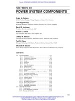
FIGURE 5-8 U.S. nuclear power generation. (Source: Energy Information Administration, Monthly Energy
Review.)
0
200
400
Billion kilowatthours
600
800
Nuclear generation, 1974 to 2004
1974 1976 1978 1980 1982 1984 1986 1988 1990 1992 1994 1996 1998 2000 2002 2004
0
1989
1990
1991
1992
1993
1994
1995
1996
1997
1998
1999
2000
2001
2002
2003
2004
20
40
60
80
100
Rising trend in generation
is driven by rising trend
in capacity factor.
Capacity factor trend, 1989 to 2004
Percent
5.2 NUCLEAR POWER PLANTS
By GEORGE H. MILEY
5.2.1 Nuclear Energy
Introduction. The United states is the world’s largest supplier of commercial nuclear power. In
2005, there were 104 U.S. commercial nuclear generating units that were fully licensed to operate.
One reactor, however, Brown’s Ferry unit 1 has been shut down since 1985. Therefore, some sources
cite only 103 units. Together, they provide about 20% of the nation’s electricity—second only to coal
as a fuel source.
The Energy Information Administration (EIA) reports that the U.S. nuclear industry generated
788,556 million kilowatt hours of electricity in 2004 (Fig. 5-8), a new U.S. (and international)
record. Although no new U.S. nuclear power plants have come on line since 1996, this is the indus-
try’s fifth annual record since 1998.
General. Applying the nuclear process for electrical production involves consideration of charac-
teristics substantially different from those associated with the use of fossil fuels. With fossil fuels or
with hydro, the amount of energy source (fuel) supplied to the power plant is proportional to the
power demanded at that time. With nuclear power, however, the fuel for a substantial amount of ener-
gy output is physically located in the converter at any time. A second important characteristic of the
nuclear process is the energy density. The thermal energy density in a typical fossil boiler (heated
volume or core volume) is in the range of 0.20 kW/L; in a typical nuclear power generator it is in
Beaty_Sec05.qxd 17/7/06 8:29 PM Page 5-16
Downloaded from Digital Engineering Library @ McGraw-Hill (www.digitalengineeringlibrary.com)
Copyright © 2006 The McGraw-Hill Companies. All rights reserved.
Any use is subject to the Terms of Use as given at the website.
GENERATION
GENERATION 5-17
the range of 80 kW/L. A third important difference is that of continued low-level heat generation
(decay heat) when the nuclear process is shut down following power operation. A fourth important
difference is that of emanations. The fossil process requires the intake of large volumes of air and
fuel and the corresponding exhaust of large volumes of waste gas, including CO
2
, SO
3
, NO
2
, etc.,
some particulate matter, and in the case of coal-fired boilers, substantial quantities of ash. The
nuclear process, however, requires only the input of the material placed in the core; its output is fuel-
element materials plus radioactive “waste” products from the fission process. This residue includes
small quantities of gases which may be released or may be stored and solids which are contained
within the fuel.
These and other more subtle aspects introduce many new considerations in the equipping and
regulation of the nuclear process.
5.2.2 Mass-Energy Relationships
One of the first applications of the special theory of relativity proposed by Einstein in 1905 was the
interrelation between mass and energy, expressed by the equation E ϭ mc
2
. Thus, a change in nuclear
mass appears as energy. If the mass m is expressed in kilograms and the velocity of light c in meters
per second, the energy E is in joules.
(5-1)
The amounts of energy involved in single nuclear events are usually very small. Thus, for conve-
nience, the electronvolt (the energy acquired by any charged particle carrying a unit electronic charge
falling through a potential of 1 V) is often used. One electronvolt (eV) ϭ 1.602 ϫ 10
Ϫ19
J and, cor-
respondingly, 1 keV ϭ 1.602 ϫ 10
Ϫ16
J. One MeV ϭ 1.602 ϫ 10
Ϫ13
.
The mass-energy relationships become
where 1 J ϭ 1 m
2
⋅ kg/s
2
.
It is often convenient to use the energy corresponding to 1 atomic mass unit (amu). One amu ϭ
1.657 ϫ 10
Ϫ27
kg (1 amu ϭ
1
ր
12
of the mass of a neutral atom of
12
C).
(5-2)
The atomic mass of a nuclide can be evaluated in terms of the masses of its constituent particles
and the binding energy (Fig. 5-9). The mass of the nuclide is less than the sum of its constituent par-
ticles in the free state. If ⌬M is the decrease in mass when a number of protons, neutrons, and elec-
trons combine to form an atom, then the mass-energy equivalence principle states that an amount of
energy equal to ⌬E ϭ c
2
⌬M is released in the process. The difference in mass ⌬M is called the mass
defect; it is the amount of mass which would be converted to energy if a particular atom or nuclide
were to be assembled from the requisite number of protons, neutrons, and electrons. The same
amount of energy would be needed to break the atom into its constituent particles, and the energy
equivalent of the mass defect is therefore a measure of the binding energy of the nuclei. The mass of
ϭ 931 MeV/amu
E
amu
ϭ 1.66 ϫ 10
Ϫ27
kg ϫ 5.61 ϫ 10
29
MeV/kg
EsMeVd ϭ massskgd ϫ 5.61 ϫ 10
29
MeV/kg
EskeVd ϭ massskgd ϫ 5.61 ϫ 10
32
keV/kg
ϭ massskgd ϫ 5.61 ϫ 10
35
eV/kg
EseVd ϭ massskgd ϫ
8.99 ϫ 10
16
m
2
/s
2
1.602 ϫ 10
Ϫ19
J/eV
ϭ massskgd ϫ 8.99 ϫ 10
16
m
2
s
2
EsJd ϭ massskgd ϫ s2.998 ϫ 10
8
m/sd
2
Beaty_Sec05.qxd 17/7/06 8:29 PM Page 5-17
Downloaded from Digital Engineering Library @ McGraw-Hill (www.digitalengineeringlibrary.com)
Copyright © 2006 The McGraw-Hill Companies. All rights reserved.
Any use is subject to the Terms of Use as given at the website.
GENERATION
5-18 SECTION FIVE
FIGURE 5-9 Mass defects and binding energies of nuclei.
the constituent particles is the sum of Z proton masses, Z electrons, and A Ϫ Z neutrons, where A
refers to the mass number of the element. Pairs of protons and electrons can be represented by hydro-
gen atoms; the loss in mass which accompanies the formation of the hydrogen atom from the proton
and an electron is negligible. The mass defect can then be written ⌬M ϭ ZM
H
ϩ (A Ϫ Z ) M
n
Ϫ M
ZA
,
where M
H
is the mass of the hydrogen atom, 1.008142 amu; M
n
is the mass of the neutron, 1.008982
amu; and M
ZA
is the mass of nuclide of concern.
Figure 5-9 provides an approximate picture of the nuclear binding energy. In the higher mass
numbers, the actual binding energy is not the same for each particle in the nucleus. After the maxi-
mum of the curve, almost every successive particle (proton or neutron) is bound less tightly than
those already present, and the overall average decreases. The binding energy represented, however,
is sufficiently accurate for engineering evaluations.
5.2.3 The Fission Process
In the higher mass numbers, several of the naturally occurring elements are radioactive or have a
characteristic which enables them to emit nuclear particles and be transmuted to different elements
as a function of time. The various naturally occurring series are designated the thorium, uranium, and
actinium series. These designations are related to the elements at or near the head of the series and
can be expressed as multiples of a number N, where N is an integer. The series are indicated by 4N,
4N ϩ 2, and 4N ϩ 3, respectively. There is no naturally occurring 4N ϩ 1 element; such an element
has been created in the process of artificial nuclear transmutation. This element is designated neptu-
nium and has the mass characteristic of 4N ϩ 1. It, too, heads a radioactive series. The four radioac-
tive series are shown in Fig. 5-10.
A number of elements with high mass numbers, both natural and artificially produced, undergo a
process of nuclear fission. In the fission process, a nucleus absorbs a neutron and the resulting compound
nucleus is so unstable that it immediately breaks up into parts. As shown by the arrow labeled
“fission” in Fig. 5-9, the fission products have a lower mass and larger binding energy, resulting in
Beaty_Sec05.qxd 17/7/06 8:29 PM Page 5-18
Downloaded from Digital Engineering Library @ McGraw-Hill (www.digitalengineeringlibrary.com)
Copyright © 2006 The McGraw-Hill Companies. All rights reserved.
Any use is subject to the Terms of Use as given at the website.
GENERATION
GENERATION 5-19
FIGURE 5-10 The four radioactive series.
a release of energy in the form of kinetic energy of the products. (Also note in Fig. 5-9 that the arrow
for “fusion” shows lighter elements fusing together to create higher mass products, again with a
release of energy by emission of high-speed products. Many of the heavy nuclides can be induced to
fission, but most only with neutrons of high energy. Naturally occurring heavy nuclides that fission
with neutrons of energy in the range of the neutrons produced by the fission are uranium isotopes
235
U and
238
U and thorium 232. In addition, artificially produced nuclides
233
U and
239
Pu, produced
by (n, ) reactions in
232
Th and
238
U, respectively, are capable of fission. The fission process, in a
nuclear reactor, is initiated by neutrons which are generated as part of the process. The general
fission process may be expressed by
(5-3 )
m
F ϩ
1
n
S
x
A ϩ
mϪsxϩCd
B ϩ C
1
n
Beaty_Sec05.qxd 17/7/06 8:29 PM Page 5-19
Downloaded from Digital Engineering Library @ McGraw-Hill (www.digitalengineeringlibrary.com)
Copyright © 2006 The McGraw-Hill Companies. All rights reserved.
Any use is subject to the Terms of Use as given at the website.
GENERATION
5-20 SECTION FIVE
where F ϭ fuel nuclide, mass number m
n ϭ neutron
A, B ϭ fragment nuclides
C ϭ number of neutrons produced
x ϭ atomic number
The percentage of nuclide production as a function of
mass number is shown in Fig. 5-11.
A typical example is the fission of
235
U with the pro-
duction of two most likely fission fragments.
(5-4)
The mass balances of this equation are
The mass change resulting from fission is
236.133 Ϫ 235.918 ϭ 0.215 amu, which by the
relationship of mass to energy is equivalent to E(J)
ϭ mass(amu) ϫ 1.49 ϫ 10
Ϫ10
J/amu, which rep-
resents ~3.2 ϫ 10
Ϫ11
J/fission or approximately
200 MeV/fission (or 3.2 ϫ 10
Ϫ11
W ⋅ s/fission).
The major portion of this energy is released
immediately as kinetic energy of the fission frag-
ments, the fission neutrons, and instantaneous
gamma rays. A portion of the energy is released
gradually from the decay of the fission frag-
ments. Table 5-3 shows the distribution of fission energy. For practical purposes, the neutrino ener-
gy, because of the low probability of interaction of neutrinos with matter, is not recoverable. (This
leaves about 190 MeV, or 3.0 ϫ 10
Ϫ11
J, recoverable per fission.)
5.2.4 Neutron Interaction
Each neutron interacting with a nucleus does not always result in fission; some are scattered and
some are involved in radiative capture, that is, initiate the radiation of other particles and/or photons
to reduce the target atom to a stable state. The neutron-absorption probability for a given nuclide is
referred to as its cross section and is expressed in units of area. Since very small areas are involved,
the special unit for cross section is the barn, equal to 10
Ϫ24
cm
2
.
The cross section for a neutron interaction varies with energy. An explanation is that, quantum
mechanically, the wavelength of the neutron is inversely proportional to its energy E or velocity,
and may be expressed by
(5-5)
l ϭ
2.86 ϫ 10
Ϫ8
2Esevd
mm
Before fission After fission
235
U – 235.124 amu
95
A –94.945 amu
1
n 1.009 amu
139
B 138.955 amu
2
1
n 2.018 amu
236.133 amu 235.918 amu
235
U ϩ
1
n
S
95
A ϩ
139
B ϩ 2
1
n
FIGURE 5-11 Fission yield.
TABLE 5-3 Distribution of Fission Energy
Energy MeV
Kinetic energy of fission fragments 168 Ϯ 5
Instantaneous gamma-ray energy 5 Ϯ 1
Kinetic energy of fission neutrons 5 Ϯ 0.5
Beta particles from fission products 7 Ϯ 1
Gamma rays from fission products 6 Ϯ 1
Neutrinos ~10
Total fission energy 201 Ϯ 6
Beaty_Sec05.qxd 17/7/06 8:29 PM Page 5-20
Downloaded from Digital Engineering Library @ McGraw-Hill (www.digitalengineeringlibrary.com)
Copyright © 2006 The McGraw-Hill Companies. All rights reserved.
Any use is subject to the Terms of Use as given at the website.
GENERATION
GENERATION 5-21
For fast neutrons (about 1 MeV), is of the order of 10
211
mm, and for thermal neutrons (about
0.03 MeV), is about 1.7 3 10
27
mm. The slower neutrons behave as though they had a diameter
approaching that of the atom, and thus have a larger probability of interaction.
5.2.5 Radiation
Nuclide Composition. The elements of the periodic table, both naturally occurring and artificial,
are composed of protons (except for hydrogen), neutrons, and electrons. Many of the elements have
two or more isotopic forms, states which have the same atomic number but a different atomic mass
because of a different number of neutrons in the nucleus.
Most of the naturally occurring elements are stable, that is, do not eject particles to change to a
different isotope or a different element. However, some naturally occurring elements, as indicated in
Fig. 5-10, are conditionally stable and have a probability for transmutation. Out of the total number
of atoms present, the probability indicates that a certain number of the atoms will, by ejecting a par-
ticle, change to an isotope or a new element. The mode of decay for a given isotope is predictable.
The pattern is sometimes complex and follows a decay chain.
Radioactive Transmutation. For every radioactive material, there are characteristic quantities that
may be used to describe the process. Each radioactive nuclide has a definite probability of decaying
in unit time. This decay probability has a constant value, characteristic of the particular radioisotope.
In a given sample, the rate of decay at any instant is proportional to the number of radioactive atoms
present at that time. If N is the number of radioactive atoms present at time t and is the decay con-
stant, the decay rate is given by dn/dt ϭ ϪN for a simple decay scheme. Integrating this over the
interval N
0
to N gives
(5-6)
where N ϭ number of atoms remaining unchanged at any time t
N
0
ϭ initial number of atoms
ϭ disintegration constant
The reciprocal of the decay constant 1/ is the mean or average life of the radioactive species ϭ t
m
.
A more widely used quantity for quantifying radioactive decay is the half-life, that period of time
during which half the atoms originally present are transmuted. If N is set equal to
1
ր
2
N
0
and the above
equation is solved for t, the value becomes
(5-7)
In a radioactive species, a nuclide may undergo successive decay before reaching the ground state. For a
compound decay scheme involving two states A and B, the net rate of change of B with time is given by
(5-8)
where the solution is N ϭ [
A
N
A0
/(
B
Ϫ
A
)] ( Ϫ )
.
The first term on the right represents the
production of B from the decay of A; the second term is the decay of B. N
A0
is the number of parent
atoms at time t ϭ 0. Sample decay curves in Fig. 5-12 show both a simple decay and a compound
two-stage decay.
If the radiation occurs by the emission of a quantity of energy (photon), the nuclide retains its
atomic weight and number. If the decay occurs by emission of a particle, the nuclide changes to an
isotope (same atomic number), an isobar (same mass number), or a different element.
Artificial elements, including those resulting from the fission process, are very likely to be radioac-
tive. In some cases, this activity results in the emission of a photon of energy to allow the atom to
reach a lower energy state. In other cases, a particle is emitted; the particle emitted for some decay-
ing nuclides is a neutron. These delayed neutrons are important to the regulation of the fission process.
e
Ϫl
B
t
e
Ϫl
A
t
dN
b
dt
ϭ l
A
N
A
Ϫ l
B
N
B
t
1>2
ϭ
ln 2
l
ϭ
0.6931
l
N ϭ N
0
e
Ϫlt
Beaty_Sec05.qxd 17/7/06 8:29 PM Page 5-21
Downloaded from Digital Engineering Library @ McGraw-Hill (www.digitalengineeringlibrary.com)
Copyright © 2006 The McGraw-Hill Companies. All rights reserved.
Any use is subject to the Terms of Use as given at the website.
GENERATION
5-22 SECTION FIVE
FIGURE 5-12 (a) Radioactive decay of a single radionuclide as a function of half-life; (b) decay of
mixture of independent radionuclides.
Types of Radiation. There are three categories of radiation emanations of biological concern in
nuclear power. The first category is that of charged particles, principally alpha particles and beta par-
ticles. The second is that of uncharged particles, chiefly neutrons. The third is that of photons or
gamma rays. The charged particles directly produce ionization by collision with neutral atoms.
Neutrons and photons indirectly produce ionization by liberating directly ionizing particles or by ini-
tiating nuclear transformations.
In radioactivity, a conventional unit is the curie, that quantity of any radioactive material giving
3.7 ϫ 10
10
disintegrations/s. For small quantities of radiation, the millicurie and the microcurie,
3.7 ϫ 10
7
and 3.7 ϫ 10
4
disintegrations/s, respectively, are frequently used. The rutherford (rd),
equal to 10
6
disintegrations/s, is sometimes used. The SI unit of radioactivity is the becquerel
[1 curie (Ci) ϭ 3.7 ϫ 10
10
becquerel (Bq)].
The radioactivity, the decay constant, and the weight are related by
(5-9)
where ϭ decay constant, disintegrations/s
W ϭ weight of the material, g
A ϭ Avogadro’s number ϭ 6.02 ϫ 10
23
atoms/mol
G
w
ϭ gram atomic weight of the material, g/mol
N ϭ number of atoms
This equation shows that a given amount of radioactivity may occur from a large mass with a small
decay rate or a small mass which has a high decay rate.
Radiation dosage is expressed in four ways:
1. Absorbed dose (D), which is the energy absorbed per unit mass at a specific place in a material.
The standard of absorbed dose is the gray; 1 Gy ϭ 1 J/kg. The special unit of absorbed dose is
the rad ϭ 0.01 J/kg ϭ 0.01 Gy. A subset is the absorbed-dose index, which is the maximum
absorbed dose, at a point, within a 300-mm-diameter sphere centered at the point and consisting
of material equivalent to soft tissue with a density of 1 g/cm
3
.
2. Dose equivalent (H). In general, the biological equivalent of a given absorbed dose depends on
the type of radiation and the irradiation conditions. The product of modifying factors, assigned to
weigh the effect on a given organ, and the absorbed dose is the dose equivalent. The special unit
of H is the rem (where D is in rads, H is in rems). A subset of this is the dose-equivalent index,
which is the maximum dose equivalent, at a point, within a 300-mm-diameter sphere centered at
the point and consisting of material equivalent to soft tissue with a density of 1 g/cm
3
.
dN
dt
ϭ lN ϭ
lW
A
G
w
Beaty_Sec05.qxd 17/7/06 8:29 PM Page 5-22
Downloaded from Digital Engineering Library @ McGraw-Hill (www.digitalengineeringlibrary.com)
Copyright © 2006 The McGraw-Hill Companies. All rights reserved.
Any use is subject to the Terms of Use as given at the website.
GENERATION
GENERATION 5-23
3. Kerma (K ), which is the sum of the initial kinetic energies of the charged particles produced by
indirectly ionizing radiation per unit mass of the material in which the interaction takes place. The
units of K are grays or rads.
4. Exposure (X) is the measure of a particular field of electromagnetic radiation (x- or gamma rays) to
ionize air. The special unit of exposure is the roentgen (R) ϭ 2.58 ϫ 10
Ϫ4
coulombs (C)/kg of air.
5.2.6 Nuclear Plant Safety
The nuclear-powered steam supply system characteristics of substantial energy potential present in
the reactor, radiation production during the fission process, and continued radiation production and
heat generation after shutdown require that special safety precautions be taken in design and opera-
tion of a nuclear plant. The health and welfare of the public depends on both the continuation of the
plant’s power production and the avoidance of any incident which would endanger the environment.
In order to achieve the latter goal and to aid the former, special regulations relating to nuclear plants
have been formulated.
Workers in power plants are covered by federal regulations, with special attention being devoted
to radiation protection. A guiding principle applied throughout the industry is known as ALARA.
This directs management and workers to seek as low an exposure as is reasonably achievable.
Application of ALARA requires careful planning and a balance between minimizing exposure ver-
sus work requirements.
5.2.7 Federal Regulations
Title 10 of the Code of Federal Regulations (10 CFR) has the following parts which are of primary
importance to nuclear power facilities:
Part 20, Standards for Protection against Radiation
Part 50, Licensing of Production and Utilization Facilities
Part 55, Operators’ Licenses
Part 70, Special Nuclear Material
Part 100, Reactor Site Criteria
There are several other parts of 10 CFR which relate to the usage or handling of radioactive mater-
ial. Most of the parts previously listed have appendixes which treat requirements for specific sub-
jects. Authority for regulation of commercial, nuclear-powered plants is vested with the U.S. Nuclear
Regulatory Commission. This authority includes the licensing of new facilities and the surveillance
of operating facilities. An applicant for a nuclear-powered plant is required to apply for a license to
construct and operate the facility. Such application includes the submission of Safety Analysis
Reports which describe the design bases, the design, and the analyses performed to show that plant
performance and conditions will be within established limits.
5.2.8 Standards
Appendix A of 10 CFR Part 50 provides general design criteria for nuclear power plants. Criterion
1 requires that structures, systems, and components important to safety be designed, fabricated,
erected, and tested to quality standards. The nuclear standards program of the American National
Standards Institute has developed a sizable group of standards for this requirement. The principal
design, systems, and operation standards are those developed by ASME, IEEE, ANS, and ISA.
Many other documents providing criteria, standard practices, or guidance are available. In the
nuclear area, specific designs have not been repeated frequently enough to accumulate a significant
backlog of experience. As a result, many of the “standards” are developed to provide leadership in
addressing given areas.
Beaty_Sec05.qxd 17/7/06 8:29 PM Page 5-23
Downloaded from Digital Engineering Library @ McGraw-Hill (www.digitalengineeringlibrary.com)
Copyright © 2006 The McGraw-Hill Companies. All rights reserved.
Any use is subject to the Terms of Use as given at the website.
GENERATION
5-24 SECTION FIVE
The Nuclear Regulatory Commission provides guidance in many areas of design, construction,
and operation through Regulatory Guides. Individual guides may cite a standard as an acceptable
method of addressing the area concerned.
5.2.9 Quality Assurance
The best defense against incidents which endanger the public is to prevent them. In a similar way,
the best system performance is effected when malfunctions are eliminated. Reliability is the inter-
face between quality assurance and safety. Reliability can neither be tested nor legislated into equip-
ment; it must be built in. High quality in design, procurement, installation, and operation will lead
to a system that has high availability, good reliability, and a low probability of incurring an accident.
Quality assurance is a total systems approach to achieving these aims. Quality assurance does rep-
resent an increase in costs; this increase must be balanced against safer operation and savings result-
ing from less time lost, fewer repairs, and better control. The prime responsibility for an effective
quality assurance program lies with the owner/operator of the plant, who may delegate portions of
the program to major suppliers.
5.2.10 Nuclear Energy System
Reactor-System Assembly. To achieve a self-sustaining, but regulated fission process, and for the
energy released to be extracted and converted to electricity, a reactor system is constructed.
The nuclear fuel, usually uranium, is fabricated into fuel elements. The typical design for the fuel of
a light-water power reactor involves the fuel in oxide form. Where the fuel is uranium, the uranium diox-
ide is fabricated into pellets, right circular cylinders approximately 19 mm high and 8 mm in diameter.
In light-water reactors, the uranium dioxide material is typically enriched to a low value, approx-
imately 3% to 7%, in the fissionable isotope
235
U. This enrichment is necessary because light water
has an appreciable neutron-absorption cross section. The extra neutrons available from the added fis-
sile material compensate for the absorption in the moderator. The fuel-pellet material is usually of a
ceramic nature (e.g., UO
2
); the pellets are dished at both ends to allow for differential thermal expan-
sion and fuel volumetric growth with burnup.
The pellets are inserted into fuel tubes, typically thin-walled tubes of stainless steel or Zircalloy.
An open space (with the column of pellets spring-loaded) at the top of the tube is provided to accom-
modate generation of gases during the fission process. The tubes are sealed top and bottom and are
assembled into a configuration involving fixed spacing in a fuel assembly. A representative fuel
assembly is shown in Fig. 5-13. This assembly has an overall length of approximately 4.5 m with an
active length of approximately 3.8 m.
Plutonium,
239
Pu, is produced in the fuel elements during power operation by the absorption of
neutrons in the
238
U. This material is fissionable and may be recovered during fuel reprocessing and
fabricated into new fuel elements. However, to date, regulations in the United States have prevented
fuel reprocessing, largely due to concerns about proliferation of materials for use in weapons.
Consequently, spent fuel from U.S. plants is currently being stored, awaiting future decisions about
reprocessing. In contrast, reprocessing plants have been constructed in Europe.
In gas-cooled reactors in the United States, the fuel-element design differs from that of light-water
reactors. The recent gas-cooled reactor elements are hexagonal graphite blocks into which blind longi-
tudinal holes are drilled to receive rods of fuel particles. The fissile material is enriched uranium carbide,
UC
2
. Kernels of this material are coated with a pyrolytic carbon–silicon carbide–pyrolytic carbon sand-
wich. Fertile material in the form of thorium oxide, ThO
2
, kernels is also used. A fertile material is one
which, by absorption of neutrons, is changed to a material which can be fissioned. In this case,
232
Th is
converted to
233
U, which has superior characteristics for fission reactions. The kernels are coated with
two layers of pyrolitic carbon. The two types of fuel particles are mixed in the proper proportions and
are formed with a carbon matrix into fuel “rods” about 15.6 mm in diameter and about 60 mm long.
These rods are inserted into the holes in the graphite blocks. Through holes are provided in the block for
the helium coolant flow. These loaded graphite blocks or “fuel assemblies” form the basic module for
the core of the gas reactor.
Beaty_Sec05.qxd 17/7/06 8:29 PM Page 5-24
Downloaded from Digital Engineering Library @ McGraw-Hill (www.digitalengineeringlibrary.com)
Copyright © 2006 The McGraw-Hill Companies. All rights reserved.
Any use is subject to the Terms of Use as given at the website.
GENERATION
GENERATION 5-25
FIGURE 5-13 PWR fuel assembly.
The required number of fuel assemblies to produce a power output desired for the reactor plant
are assembled into a reactor-core configuration approximating a right circular cylinder. This config-
uration provides a high volume-to-surface ratio which minimizes the neutron leakage and conserves
the neutrons produced for further fission action. For a 1300-MW (electrical) light-water nuclear
plant, a representative core assembly might involve 241 fuel assemblies each weighing approxi-
mately 660 kg, for a core equivalent diameter of 3.6 m, a core height of approximately 5 m, and a
total core weight of approximately 160 metric tons.
Control-Element Assemblies. In each fuel assembly, several holes are shown. These open holes are
spaces into which control elements are inserted for regulation of the fission process. The individual
control elements may be grouped typically into control-element assemblies. Control elements for cur-
rent Pressurized Water Reactors (PWRs) (Fig. 5-22) are located in the fuel elements in this fashion.
Control elements of Boiling Water Reactors (BWRs) are blade-type cruciform units. These units are
inserted into or withdrawn from the spaces between the fuel assemblies. The control-element assem-
blies are selected from a material which absorbs neutrons; therefore, by insertion into the fuel assem-
bly or withdrawal from the fuel assembly, the amount of neutrons available for fission production can
be reduced or increased, respectively, as required for reactor-system performance. These control-
element assemblies are inserted or withdrawn by electromechanical or hydraulic drive mechanisms.
Moderator and Heat-Transfer Medium. The thermal energy released from the core must be conveyed
to the electric generator at a rate and in a fashion which meets the requirements. Some consideration has
been given to the use of a reactor core to heat gas which is supplied to a magnetohydrodynamic gener-
ator. However, commercial systems for the present and near future will continue to use steam turbines
as the motive power for the generator.
Beaty_Sec05.qxd 17/7/06 8:29 PM Page 5-25
Downloaded from Digital Engineering Library @ McGraw-Hill (www.digitalengineeringlibrary.com)
Copyright © 2006 The McGraw-Hill Companies. All rights reserved.
Any use is subject to the Terms of Use as given at the website.
GENERATION