handbook for electrical engineers hu (5)
Bạn đang xem bản rút gọn của tài liệu. Xem và tải ngay bản đầy đủ của tài liệu tại đây (638.75 KB, 28 trang )
SECTION 6
PRIME MOVERS
Former contributors: William H. Day, Donald H. Hall, and Lawrence R. Mizin.
CONTENTS
6.1 STEAM PRIME MOVERS . . . . . . . . . . . . . . . . . . . . . . . . . . .6-1
6.1.1 Steam Engines and Steam Turbines . . . . . . . . . . . . . .6-1
6.1.2 Steam-Engine Types and Application . . . . . . . . . . . . .6-2
6.1.3 Steam-Engine Performance . . . . . . . . . . . . . . . . . . . .6-2
6.1.4 Steam Turbines—General . . . . . . . . . . . . . . . . . . . . .6-3
6.1.5 Turbine Efficiency . . . . . . . . . . . . . . . . . . . . . . . . . . .6-5
6.1.6 Turbine Construction . . . . . . . . . . . . . . . . . . . . . . . . .6-7
6.1.7 Turbine Control and Protective Systems . . . . . . . . . . .6-9
6.1.8 Lubrication and Hydraulic Systems . . . . . . . . . . . . .6-13
6.1.9 Oil-Seal and Gas-Cooling Systems
for Hydrogen-Cooled Generators . . . . . . . . . . . . . . .6-14
6.1.10 Miscellaneous Steam-Turbine Components . . . . . . .6-14
6.2 STEAM-TURBINE APPLICATIONS . . . . . . . . . . . . . . . . . .6-14
6.2.1 Central-Station Turbines . . . . . . . . . . . . . . . . . . . . . .6-14
6.2.2 Industrial Steam Turbines . . . . . . . . . . . . . . . . . . . . .6-15
6.2.3 Variable-Speed Turbines . . . . . . . . . . . . . . . . . . . . . .6-15
6.2.4 Special-Purpose Turbines . . . . . . . . . . . . . . . . . . . . .6-16
6.3 STEAM-TURBINE PERFORMANCE . . . . . . . . . . . . . . . . .6-16
6.3.1 Rankine-Cycle Efficiency . . . . . . . . . . . . . . . . . . . . .6-16
6.3.2 Engine Efficiency . . . . . . . . . . . . . . . . . . . . . . . . . . .6-17
6.3.3 Theoretical Steam Rates . . . . . . . . . . . . . . . . . . . . . .6-18
6.3.4 Condensing-Turbine Efficiencies . . . . . . . . . . . . . . .6-18
6.3.5 Regenerative Cycle . . . . . . . . . . . . . . . . . . . . . . . . .6-18
6.3.6 Reheat Cycle . . . . . . . . . . . . . . . . . . . . . . . . . . . . . .6-19
6.3.7 Gross and Net Heat Rates . . . . . . . . . . . . . . . . . . . . .6-19
6.3.8 Nuclear Cycles . . . . . . . . . . . . . . . . . . . . . . . . . . . . .6-20
6.3.9 Combined Cycles . . . . . . . . . . . . . . . . . . . . . . . . . . .6-22
6.3.10 Noncondensing-Turbine Efficiencies . . . . . . . . . . . .6-22
6.3.11 Automatic-Extraction-Turbine Efficiencies . . . . . . . .6-22
BIBLIOGRAPHY . . . . . . . . . . . . . . . . . . . . . . . . . . . . . . . . . . . . .6-23
6.4 GAS TURBINES . . . . . . . . . . . . . . . . . . . . . . . . . . . . . . . . .6-23
6.4.1 Cycles . . . . . . . . . . . . . . . . . . . . . . . . . . . . . . . . . . .6-23
6.4.2 Design . . . . . . . . . . . . . . . . . . . . . . . . . . . . . . . . . . .6-25
6.4.3 Performance . . . . . . . . . . . . . . . . . . . . . . . . . . . . . . .6-26
6.4.4 Applications . . . . . . . . . . . . . . . . . . . . . . . . . . . . . . .6-26
BIBLIOGRAPHY . . . . . . . . . . . . . . . . . . . . . . . . . . . . . . . . . . . . . .6-27
6.1 STEAM PRIME MOVERS
6.1.1 Steam Engines and Steam Turbines
Steam prime movers are either reciprocating engines or turbines, the former being the older, domi-
nant type until 1900. Reciprocating engines offer low speed (100 to 400 r/min), high efficiency in
small sizes (less than 500 hp), and high starting torque. In the Industrial Revolution, they powered
6-1
Beaty_Sec06.qxd 18/7/06 4:15 PM Page 6-1
Downloaded from Digital Engineering Library @ McGraw-Hill (www.digitalengineeringlibrary.com)
Copyright © 2006 The McGraw-Hill Companies. All rights reserved.
Any use is subject to the Terms of Use as given at the website.
Source: STANDARD HANDBOOK FOR ELECTRICAL ENGINEERS
6-2 SECTION SIX
mills and steam locomotives. Steam turbines are a product of the twentieth century and have estab-
lished a wide usefulness as prime movers. They completely dominate the field of power generation
and are a major prime mover for variable-speed applications in ship propulsion (through gears), cen-
trifugal pumps, compressors, and blowers. Single steam turbines can be built in greater capacities
(over 1,000,000 kW) than any other prime mover. Turbines offer high speeds (1800 to 25,000 r/min)
and high efficiencies (over 85% in larger units); require minimum floor space with relatively low
weight; need no internal lubrication; and operate at high steam pressures (5000 lb/in
2
[gage]), high
steam temperatures (1050°F), and low vacuums (0.5 inHg [abs]). Steam turbines have no recipro-
cating mass (with resulting vibrations) nor parts subject to friction wear (except bearings), and con-
sequently provide very high reliability at low maintenance costs.
6.1.2 Steam-Engine Types and Application
The former great diversity in engine types has been reduced so that (1) simple D-slide engines (less
than 0.100 hp) are used for auxiliary drive and (2) single-cylinder counterflow and uniflow engines
(less than 1000 hp), with Corliss or poppet-type valve gear, are used for generator or equipment drive
in factories, office buildings, paper mills, hospitals, laundries, and process applications (where non-
condensing by-product power operations prevail). Multiple-expansion, multicylinder constructions
are largely obsolete except for some marine applications. Although engines as large as 7500 kW have
been built and are still found in service, the field is generally limited to engines less than 500 kW in
size. Engine governing is by flyball or flywheel types to (1) throttle steam supply or (2) vary cutoff.
6.1.3 Steam-Engine Performance
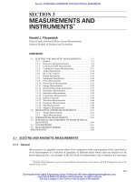
The basic thermodynamic cycle is shown in Fig. 6-1. The net work of the cycle is represented by the
area enclosed within the diagram and is represented by the mean effective pressure (mep), that is, the
net work (area) divided by the length of the diagram. The power output is computed by the “plan”
equation:
(6-1)
where hp ϭ horsepower; p
m
ϭ mep, pounds per square inch; L ϭ length of stroke, feet; a ϭ net
piston area, square inches; and n ϭ number of cycles completed per minute.
hp ϭ
p
m
Lan
33,000
FIGURE 6-1 Pressure-volume diagram for a steam-engine cycle. Phase 1-2, constant-pressure admission at P
i
;
phase 2-3, expansion, pv ϭ C; phase 3-4, release; phase 4-5, constant-pressure exhaust pipe at P
b
; phase 5-6,
compression, pv ϭ C; phase 6-1, constant-volume admission.
Beaty_Sec06.qxd 17/7/06 8:31 PM Page 6-2
Downloaded from Digital Engineering Library @ McGraw-Hill (www.digitalengineeringlibrary.com)
Copyright © 2006 The McGraw-Hill Companies. All rights reserved.
Any use is subject to the Terms of Use as given at the website.
PRIME MOVERS
PRIME MOVERS 6-3
The theoretical mep and horsepower are larger than the actual indicated values and are custom-
arily related by a diagram factor ranging between 0.5 and 0.95. The shaft or brake mep and horse-
power are lower still, with mechanical efficiency ranging between 0.8 and 0.95.
6.1.4 Steam Turbines—General
1. Expansion of steam through nozzles and buckets. Basically, steam turbines are a series of cal-
ibrated nozzles through which heat energy is converted into kinetic energy which, in turn, is trans-
ferred to wheels or drums and delivered at the end of a rotating shaft as usable power.
2. Impulse, reaction, and Curtis staging. Turbines are built in two distinct types: (1) impulse and
(2) reaction. Impulse turbines have stationary nozzles, and the total stage pressure drop is taken
across them. The kinetic energy generated is absorbed by the rotating buckets at essentially constant
static pressure. Increased pressure drop can be efficiently utilized in a single stage (at constant wheel
speed) by adding a row of turning vanes or “intermediates” which are followed by a second row of
buckets. This is commonly called a Curtis or 2-row stage.
In the reaction design, both the stationary and rotating parts contain nozzles, and an approxi-
mately equal pressure drop is taken across each. The pressure drop across the rotating parts of
reaction-design turbines requires full circumferential admission and much closer leakage control.
To illustrate the variations in energy-absorbing capacities of an impulse stage, a 2-row impulse
stage, and a reaction stage, one must start with the general energy equation as applied to a nozzle:
(6-2 )
which is reduced to
(6-3)
where V
1
is assumed to be zero, and ∆H is the enthalpy drop (isentropic expansion) in Btu per pound
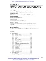
as obtained from the Mollier chart for steam (Fig. 6-2).
Assuming a typical wheel pitch line speed (W ) of 550 ft/s and initial steam conditions of 400 lb/in
2
(abs.), 700°F (H
1
ϭ 1363.4 Btu/lb), the optimum energy-absorbing capacities of each type can be derived.
Table 6-1 illustrates that the energy-absorbing capability of the Curtis stage is 4 times that of an
impulse stage and 8 times that of a reaction stage.
Because of this capability, the 2-row Curtis stage has found many applications in the process
industries for small mechanical-drive use (up to 1000 hp) where the inlet steam can be taken from
one process header and the exhaust steam sent out to a lower-pressure process header. As energy
costs increase, however, the lower efficiency attainable with these small-volume-flow single-stage
units offsets some of the desirable features (e.g., speed control, low cost, etc.). All modern turbines
over 1000 hp are multistage for good efficiency, varying from 3 to 4 stages on noncondensing units
with a small pressure ratio up to 20 or more stages on large reheat condensing units. Reaction
(Parsons) designs generally have more stages than impulse (Rateau) designs. All large units have an
impulse (1- or 2-row) first stage because there is no pressure drop on the moving rows, which makes
it more suitable for partial-arc admission.
3. The control stage. The first stage of the turbine must be designed to pass the maximum flow
through the unit at rated inlet steam conditions. The pressure required at less than rated flow will
decrease if the nozzle area is held constant, resulting in a throttling loss through the control valves
of the unit at partial flows. Very early in the development of steam turbines, it was recognized that
if full throttle pressure could be made available to the first-stage nozzles across the load range, the
maximum isentropic energy that would be available for work and overall efficiency would be
increased at part load. Most first stages now use sectionalized first-stage nozzle plates with 4, 6, or
8 separate ports (depending on steam conditions, unit size, and manufacturer).
Jet velocity, ft/s ϭ 223.7!⌬H
V
1
2
2gJ
ϩ H
1
ϭ
V
2
2
2gJ
ϩ H
2
Beaty_Sec06.qxd 17/7/06 8:31 PM Page 6-3
Downloaded from Digital Engineering Library @ McGraw-Hill (www.digitalengineeringlibrary.com)
Copyright © 2006 The McGraw-Hill Companies. All rights reserved.
Any use is subject to the Terms of Use as given at the website.
PRIME MOVERS
6-4 SECTION SIX
FIGURE 6-2 Mollier chart for steam (ASME steam tables.)
Beaty_Sec06.qxd 17/7/06 8:31 PM Page 6-4
Downloaded from Digital Engineering Library @ McGraw-Hill (www.digitalengineeringlibrary.com)
Copyright © 2006 The McGraw-Hill Companies. All rights reserved.
Any use is subject to the Terms of Use as given at the website.
PRIME MOVERS
PRIME MOVERS 6-5
TABLE 6-1 Energy-Absorbing Capability of the Curtis Stage
2-row
Reaction
Stage type Impulse wheel Sta. Rot. Combined
Theoretical W/V for 0.50 0.25 . . . . . . 0.707
peak efficiency
Required jet velocity, ft/s 1100 2200 550 550
∆H required, Btu/lb 24.2 96.6 6.045 6.045 12.09
Required P
2
lb/in
2
(abs) 327 168 380.6 361.9 361.9
from Mollier chart
Stage P
1
/P
2
1.224 2.38 1.052 1.105 1.105
Note: 1 ft/s ϭ 0.3048 m/s; 1 lb/in
2
ϭ 0.06895 bar; 1 Btu/lb ϭ 2.326 kJ/kg.
The flow to each port is controlled by its own valve, and the valves are opened sequentially. As
each valve is opened to its governing point, the full throttle pressure (minus stop-valve and control-
valve pressure loss) becomes available to the arc of nozzles fed by that valve. The overall result is a
greater availability of energy to do work.
4. Steam-path design. Condensing-turbine sizes increase with the development of longer last-
stage buckets and, consequently, the last-stage dimensions (length and diameter) are the first to be
determined; these dimensions fix the diameter of the L-1 stage and the optimum energy (pressure
drop) which can be placed on that stage. This stage in turn defines the parameters of the L-2 stage
and so on up to the first stage, and it can be said that steam paths of turbines are designed backward
except for the first stage. In the 1970s, the largest-capacity single-flow condensing turbine was
approximately 120,000 kW. Larger ratings are obtained by multiplying the number of exhaust stages
(usually the last 5 to 7 stages are involved) by 2, 4, 6, or 8 times to satisfy the rating requirements.
This practice is limited to the larger blades to round out a product line to well over 1,000,000 kW.
6.1.5 Turbine Efficiency
1. Nozzle and bucket. The turbine stage efficiency
is defined as the actual energy delivered to the rotat-
ing blades divided by the ideal energy released to
the stage in an isentropic expansion from P
1
to P
2
of
the stage. The most important factors determining the
stage efficiency are the relationship of the mean
blade speed to the theoretical steam velocity, the
aspect ratio (blade length/passage width), and the
aerodynamic shape of the passages. Figure 6-3
describes the typical variation in nozzle and bucket
efficiencies with velocity ratio and nozzle height.
2. Losses
Clearance leakage. A 100% efficiency cannot be
obtained because of friction in the blading and
clearance between the stationary and rotating
parts, and because the nozzle angle cannot be zero
degrees. Axial clearance increases in the stages further from the thrust bearing to satisfy the need
to maintain a minimum clearance at extreme operating conditions when the differential expansion
between the light rotor and heavy casing is at its worst. To reduce this leakage, radial spillbands
are used. These thin, metal-strip seals may be attached to the diaphragm or casing and extend
close to the shroud bands covering the rotating blades. This clearance can be kept quite close
(0.020 to 0.060 in), and axial changes in the rotor position do not affect the clearance since the
FIGURE 6-3 Approximate relative efficiencies of
turbine stage types.
Beaty_Sec06.qxd 17/7/06 8:31 PM Page 6-5
Downloaded from Digital Engineering Library @ McGraw-Hill (www.digitalengineeringlibrary.com)
Copyright © 2006 The McGraw-Hill Companies. All rights reserved.
Any use is subject to the Terms of Use as given at the website.
PRIME MOVERS
6-6 SECTION SIX
spillbands ride over the shrouds. The need to control the clearance leakage area is especially
important on reaction stages with small blade heights because of the pressure drop across the
moving blades.
Nozzle leakage. Leakage around the nozzles between the bore of the blade ring or nozzle
diaphragm and the drum or rotor must be kept to a minimum. This leakage is controlled through
the use of a metallic labyrinth packing which consists of a single ring with multiple teeth arranged
to change the direction of the steam as well as to minimize the leakage area. Labyrinth packings
are also used at the shaft ends to step the pressure down at the high-pressure end and to seal the
shaft at the vacuum end.
Rotation loss. Rotation of the rotor consist of losses due to the rotation of the disks, the blades,
and shrouds. Partial-arc impulse stages have a greater windage loss within the idle buckets.
Rotation losses vary directly with the steam density, the fifth power of the pitch diameter, and the
third power of the rpm. In general, the windage loss amounts to less than 1% of stage output at
normal rated output. At no-load conditions, windage loss for noncondensing turbines approxi-
mates 1.5% of the rating per 100 lb/in
2
exhaust pressure, and on condensing units approximates
from 0.4% to 1.0% of the rating at 1.5 inHg (abs) exhaust pressure.
Carryover loss. A carryover loss (about 3%) occurs on certain stages when the kinetic energy of
the steam leaving the rotating blades cannot be recovered by the following stage because of a dif-
ference in stage diameters or a large axial space between adjacent stages. Typically, this happens
in control stages and in the last stages of noncondensing sections. The last stages of condensing
turbines have the largest carryover losses (normally referred to as exhaust loss) because of the
large variations in exhaust volumetric flow with exhaust pressure and the large variation of stage
pressure ratio with load. Stages preceding the last operate with essentially a constant pressure
ratio down to very low loads and consequently can be designed for peak efficiency at a wide
range of loads.
Leaving loss. Condensing turbines are frequently “frame sized” by last-stage blade height. It is
sometimes economical to size the unit with exhaust loss equal to 5% deterioration in overall tur-
bine performance at the design point (valves wide-open throttle flow and 1.5 inHg [abs] exhaust
pressure) when the normal expected exhaust pressure will be higher or the unit will be operating
at part load for a large part of the time.
Nozzle end loss, partial arc. Control stages and partial-arc impulse stages are subject to end losses
at the interface of the active and inactive portions of the blading as the stagnant steam within the
idle bucket passages enters the active arc of nozzles and must be accelerated. There is also a
greater turbulence in the steam jet at both ends of the active arc. In partial-arc impulse stages, the
increase in efficiency due to larger blade heights (aspect ratio) is partially offset by increased
rotation and end losses, and there is an optimum to this proportioning beyond which there is an
overall loss.
Supersaturation and moisture loss. Moisture in the steam causes supersaturation and moisture
losses in the stage. The acceleration of the moisture particles is less than that of the steam, caus-
ing a momentum loss as the steam strikes the particles. The moisture particles enter the moving
blades (buckets) at a negative velocity relative to the blades, resulting in a braking force on the
back of the blades. Supersaturation is a temporary state of supercooling as the steam is rapidly
expanded from a superheated state to the wet region before any condensation has begun. The den-
sity is greater than when in equilibrium, resulting in a lower velocity as the steam leaves the noz-
zle. As soon as some condensation occurs at approximately 3.5% moisture, according to Yellot,
a state of equilibrium is almost instantly achieved and supersaturation ceases.
3. Turbine efficiency. The internal used energy of the stage is obtained by multiplying the isen-
tropic energy available to the stage by the stage efficiency. The sum of the used energies of all stages
in the turbine represents the total used energy of the turbine. The internal efficiency of the turbine
can be obtained by dividing the total used energy by the overall isentropic available energy from
throttle pressure and temperature conditions to the exhaust pressure. (Note: The sum of the available
energies of the stages is greater than the overall available energy and represents the reheat factor or
Beaty_Sec06.qxd 17/7/06 8:31 PM Page 6-6
Downloaded from Digital Engineering Library @ McGraw-Hill (www.digitalengineeringlibrary.com)
Copyright © 2006 The McGraw-Hill Companies. All rights reserved.
Any use is subject to the Terms of Use as given at the website.
PRIME MOVERS
PRIME MOVERS 6-7
FIGURE 6-4 (a) Condensing turbines (exhaust at backpressures less than atmospheric);
(b) noncondensing turbines (wide range of backpressures). (General Electric.)
gain attributable to the unused energy of preceding stages becoming available to following stages.)
The use of overall available energy will automatically account for pressure-drop losses occurring in
stop valves, control valves, exhaust hood, and piping between HP and LP elements. Other losses which
must be accounted for to arrive at the turbine overall efficiency include valve-stem and shaft-end pack-
ing leakages and bearing and oil-pump losses. Determination of the overall efficiency of a turbine and
its driven equipment must take into account the losses of gears or generators and their bearings as well.
6.1.6 Turbine Construction
Since the early 1900s, horizontal-shaft units have been universally used. Horizontal units may be single-
shaft or double-shaft, with single, double, or triple steam cylinders on one shaft. These modern units
may be throttle or multiple-nozzle governed, have one or more steam extraction points, and exhibit
innumerable variations in construction. Figure 6-4 shows several of the more commonly used types
of turbines in schematic cross sections.
Steam turbines may be classified into several broad categories, according to the basic purpose and
design of the steam path: (1) straight condensing, (2) straight noncondensing, (3) uncontrolled
extraction, (4) single, double, or triple controlled extraction, and (5) reheat. Various combinations of
these features may be present in a typical unit, and occasionally unusual variations on the above
types may be seen.
Figure 6-5 is a cross section of a modern automatic-extraction turbine, showing the details of con-
struction. A steam turbine consists of the following basic parts: (1 to 3) steam path made up of rotating
Beaty_Sec06.qxd 17/7/06 8:31 PM Page 6-7
Downloaded from Digital Engineering Library @ McGraw-Hill (www.digitalengineeringlibrary.com)
Copyright © 2006 The McGraw-Hill Companies. All rights reserved.
Any use is subject to the Terms of Use as given at the website.
PRIME MOVERS
6-8 SECTION SIX
FIGURE 6-5 Cross section of a modern single-automatic-extraction noncondensing steam turbines showing construction details. (General
Electric.)
and stationary blading (buckets and nozzles); (4) casing to contain the stationary parts and act as a
steam pressure vessel; (5 to 8) controlling and protective valves, piping, and associated components
to accept and control the steam admitted to the steam path; (9 and 10) packing and sealing arrange-
ment to prevent steam from escaping into the surrounding area; (11) front standard which houses
lubrication, control, and protective equipment and supports part of the casing; (12 to 14) set of jour-
nal and thrust bearings to support the rotating elements and absorb all static and dynamic rotor loads;
(15) lubrication and hydraulic system for supplying bearing lubrication and (when applicable) gen-
erator seals, control, and protective oil requirements; (16) supporting foundation on which the major
stationary parts rest; and (17 to 20) various accessory components, such as turning gear, control and
protective components, drain valves, etc., as required by the specific application.
Turbines are constructed chiefly of carbon, alloy, and stainless steels. The rotor may be a single
forging, fabricated from a shaft and separate wheels, or constructed of forged elements welded
together. The buckets forming the rotating portion of the steam path are generally machined from
solid stock and attached by pins, or grooves called “dovetails,” to the wheels. The stationary steam
path is built up of diaphragms with nozzles mounted in the heavy, two-piece casing (usually cast
steel), which is bolted together on a horizontal joint. If the unit is condensing or has a low back pres-
sure, the exhaust casing may be made up as a separate assembly and bolted to the main casing
through a vertical joint. To minimize thermal stresses in high-temperature applications (950 to
1050°F), a double shell casing may be used. The rotor may sometimes be made in two pieces and
coupled together, particularly in the case of the larger condensing double-flow units. A solid or flex-
ible coupling may be used to connect the turbine rotor to its load.
Beaty_Sec06.qxd 17/7/06 8:31 PM Page 6-8
Downloaded from Digital Engineering Library @ McGraw-Hill (www.digitalengineeringlibrary.com)
Copyright © 2006 The McGraw-Hill Companies. All rights reserved.
Any use is subject to the Terms of Use as given at the website.
PRIME MOVERS
PRIME MOVERS 6-9
Labyrinth-type packing rings, consisting of high and low teeth, are arranged at the ends of the
steam path to inhibit steam from escaping into the surrounding area. (Similar packing is used at each
diaphragm, and particularly at stages having control valves, to prevent excessive leakage from one
stage to another within the steam path.) Associated with the external packing is a seal system which
draws a vacuum to exhaust a mixture of leaking steam and air and thus prevents any steam from leak-
ing into the surrounding room.
Bearings for supporting the turbine rotor are located in pedestals at either end and consist of jour-
nals and a thrust assembly. Normally, when steam flows through the turbine, thrust is developed in
the direction of steam flow. However, unusual operating conditions or configurations often cause a
thrust reversal. Therefore, it is usually necessary to provide an “active” thrust bearing for normal
loading and an “inactive” thrust bearing for reverse loading.
The control-valve gear-activating equipment in a turbine usually is mounted on top of the turbine
casing at the stage where steam is to be admitted. There are at least as many valve-gear assemblies
as there are control stages, sometimes more if a lower valve-gear assembly is required for passing the
flow. Protective or emergency valves are generally located off the machine, near the associated steam
piping. Control, protective, and accessory components are often located in part in the front standard,
at the pedestal housing the first journal and thrust bearing assemblies. The unit is usually supported
on its foundation at the front standard and at the exhaust casing. The coupled generator shares simi-
lar foundation supports.
6.1.7 Turbine Control and Protective Systems
Steam turbines require a number of systems and components to provide control and protective capa-
bility. These may be divided into two functional categories: (1) primary control systems and (2)
secondary and/or protective control systems.
Primary Control Systems. Primary control systems may be further subdivided into the following
elements: control valves and associated operating gear, speed/load control, and pressure control.
Secondary or protective systems consist of overspeed limiting devices, emergency valves, trip
devices, and associated alarm devices.
Control-Valve Gear. Most modern turbine-generators use steam-admission control-valve
designs which are as efficient as practical, in terms of pressure drop and throttling losses. Most pop-
ular are the ball-venturi valves used in the inlet stages of modern high-pressure units. The use of mul-
tiple valves, with the efficient venturi seat configuration and the tight-seating ball valves, permits
partial-arc nozzle admission to the turbine with good part-load efficiency and a sequential opening
action which produces nearly linear flow curves. These valves may be opened by one of two basic
means: bar lift, with valves sequenced by stem lengths, or cam-operated by levers and rollers, to lin-
earize the inherently nonlinear flow characteristics of ball-venturi valves. A common variation of the
ball-venturi valve gear once widely used is the poppet-valve gear, with beveled valves and seats. This
arrangement is not as efficient as a ball-venturi valve gear and is not presently very popular.
Another commonly employed valve gear, particularly on lower-pressure high-volume-flow appli-
cations, is the double-seated spool valve gear. This valve is not very efficient but passes high-volume
flow and can be programmed to open in a manner similar to a ball-venturi valve.
A third scheme used somewhat in the past, but now less popular, is the grid valve, which consists
of two plates with specially shaped holes arranged so that when one is rotated relative to the other,
the flow area is developed as the holes coincide. High volume flow and short physical span are the
grid valve’s strong points, but its efficiency and accuracy are not good, and operating forces are high.
Speed/Load Control Systems. After a choice has been made from the types of valves available
for steam admission to the turbine, a means must be provided for positioning these valves to obtain
basic speed/load control. The primary requirement is the maintenance of an accurate, predetermined
rotating speed, since all turbines are designed to operate at a specific speed or over a specific range
of speeds. Every turbine, therefore, has some type of speed governor or, more generally, “speed/load
control system.” Its purpose is to maintain a relationship between actual turbine speed and some ref-
erence value, over a wide range of load torques.
Beaty_Sec06.qxd 17/7/06 8:31 PM Page 6-9
Downloaded from Digital Engineering Library @ McGraw-Hill (www.digitalengineeringlibrary.com)
Copyright © 2006 The McGraw-Hill Companies. All rights reserved.
Any use is subject to the Terms of Use as given at the website.
PRIME MOVERS
6-10 SECTION SIX
Land turbines used for power generation gener-
ally operate at a specific rated speed whereas
marine and mechanical-drive turbines, because of
the inherent coupling characteristics between
rotating blades and fluids, operate over a range of
speeds.
In most of the Western Hemisphere, the accepted
operating frequency for turbine-generator machinery
is 60 Hz. Such units having a 2-pole generator must,
therefore, operate at 60 r/s, or 3600 r/min. A 4-pole
unit operating at 60 Hz will rotate at half the speed
of a 2-pole unit, or 1800 r/min. Most units in the
United States operate at either 1800 or 3600 r/min.
In most of the remainder of the world, the accepted
electric frequency is 50 Hz, with common operating
speeds of 1500 or 3000 r/min. In order to understand
steam-turbine speed/load control, it is helpful to
consider the example of constant-speed/load-based
utility or industrial units.
Figure 6-6 shows the relationship designed into
the speed/load control system of most such units
built in the United States. The commonly accepted
speed “droop,” with load, for such a system is (–)
5% for 100% load change, based on a given
speed/load reference setting. Note that speed
droops proportionally with increasing load, on a steady-state basis. The system should be so
designed that a steady-state error in speed is required to provide the command signal to move the
control valve gear to accept the required load.
If such a unit operates independently, the speed/load characteristic will be as shown by the solid
line in Fig. 6-6 (point A). If the unit is tied to a system much larger than itself, and the same system
load change occurs, obviously the effect on the unit will be much less, and speed will not vary as
much. The system is said to be “stiff” compared to the unit. Since speed accuracy is very important
if the operating unit is isolated, any speed droop experienced with a load change (point B) must be
corrected by changing the speed/load reference setting. This is illustrated by the dashed line of Fig. 6-6,
where a 50% load change was followed by a reference correction to restore rated speed (point C).
If an operating unit is tied to a “stiff” system, and it must accept more of the system load, a similar
adjustment will cause it to pick up load with no change in speed, as the dashed line shows.
Manual speed/load reset, therefore, permits a unit, whether isolated or tied to a system, to be set
to hold speed, or carry load, as the operator desires. However, if such a unit is to operate for long
periods of time, and under varying load conditions, manual load reset is an inadequate solution to
the problem of maintaining speed accuracy. In such cases, the use of an automatic reset device or
“speed corrector” to provide isochronous control is common.
Figure 6-7 shows a very simple form of speed/load control system: a mechanical speed governor
suitable for very small turbines. This type of governor uses a spring-load mechanical flyball mech-
anism connected to a throttling valve to directly control steam admission to the turbine. On larger
units, where the forces required are too high for direct operation, a hydraulic relay governing sys-
tem, as shown in Fig. 6-8, is used. In this arrangement a centrifugal flyball-type governor is con-
nected through linkage to a double-spooled pilot valve. Oil is admitted to the pilot valve, so that
when the valve moves, it ports fluid either into or out of an operating cylinder as required. The
motion of the cylinder restores the pilot valve, through another linkage, to maintain a stable rela-
tionship between the pilot valve and its cylinder. Available force for operating the control valves is
multiplied many times with this arrangement. On units larger than about 1000 kW, a mechanical
hydraulic control system having two or more such hydraulic relays or amplifiers is used to multiply
available force and to operate multiple control-valve gear systems.
FIGURE 6-6 Steady-state speed/load regulation for
a given reference setting in the speed/load system of a
steam turbines. (General Electric.)
Beaty_Sec06.qxd 17/7/06 8:31 PM Page 6-10
Downloaded from Digital Engineering Library @ McGraw-Hill (www.digitalengineeringlibrary.com)
Copyright © 2006 The McGraw-Hill Companies. All rights reserved.
Any use is subject to the Terms of Use as given at the website.
PRIME MOVERS
PRIME MOVERS 6-11
FIGURE 6-8 Governor with hydraulic power
amplifier.
FIGURE 6-9 Schematic diagram of a basic electro-hydraulic speed/load control system. (General Electric.)
The electrohydraulic control system offers greater accuracy, higher operating forces, remote and
centralized control capability, and more options and flexibility than any previous system. The
speed/load control system in Fig. 6-9, consists of (1) a permanent magnet generator or digital-type
reluctance pickup to provide a shaft-speed signal, (2) electronic circuitry for comparing the speed
signal with a reference signal, (3) a high-gain servo valve to convert the resulting electric signal to a
hydraulic signal, (4) a valve-gear power-actuator assembly capable of operating on high-pressure
hydraulics on receipt of the servo-valve signal, (5) a feedback transducer on the power actuator to
restore the servo valve to a stable condition when the desired valve position is reached, and (6) a
high-pressure hydraulic system to provide the force required.
FIGURE 6-7 Mechanical governor for small
turbines.
Beaty_Sec06.qxd 17/7/06 8:31 PM Page 6-11
Downloaded from Digital Engineering Library @ McGraw-Hill (www.digitalengineeringlibrary.com)
Copyright © 2006 The McGraw-Hill Companies. All rights reserved.
Any use is subject to the Terms of Use as given at the website.
PRIME MOVERS
6-12 SECTION SIX
Other types of speed/load control systems have been applied to turbines from time to time. These
include pneumatic, hydraulic, or electric devices. However, the two most common systems for tur-
bine control are the mechanical hydraulic control (MHC) and electrohydraulic control (EHC) sys-
tems described. Another version of the EHC system was developed in the late 1960s to provide
bridge control on marine turbine applications.
Pressure Control Systems. A second major area of control technology on steam turbines deals
with process control. In industrial power plants particularly, it is often economical to generate and
control several process flows, using steam from available steam turbines. As in the case of speed/load
control, when a process is to be controlled, a definite relationship or “regulation” is established
between the flow to be supplied by the turbine and the pressure. However, the possible options in
process-pressure-control management are much greater than the speed/load control options
described. The most common application control is for an extraction or exhaust flow from a turbine,
which is to be controlled accurately in pressure and used in an industrial process. For this purpose,
automatic-extraction and exhaust pressure control systems have been designed, using both the MHC
and EHC technologies. Occasionally, particularly on waste-heat boiler applications, there is a need
for initial pressure control as well.
Figure 6-10 is a greatly simplified schematic representation of a mechanical hydraulic control
system on a single-automatic-extraction condensing turbine. The unit consists of two turbines, an HP
and an LP section (each supplied by a separate valve gear), on one shaft. A flyball speed governor is
used to move the two sets of valves to control speed, or load, and a bellows-type pressure governor
is employed to sense process pressures and move the valves in opposite directions to control process
flow and pressure. (Actual hardware required for these actions would, of course, include either
mechanical hydraulic relays and linkage or electrohydraulic components.) The system is usually so
designed that load and process flow variations can be satisfied at the same time with a minimum of
interaction between the two variables.
Often the need exists as well for control of exhaust pressure on a noncondensing turbine-generator.
In this case, since the number of variables which can be controlled is only equal to the number of
control-valve stages, one variable must be sacrificed. Usually, the unit is tied to a “stiff” electrical
FIGURE 6-10 Simplified schematic diagram of a speed and pressure control system for
a single-automatic-extraction condensing turbine. (General Electric.)
Beaty_Sec06.qxd 17/7/06 8:31 PM Page 6-12
Downloaded from Digital Engineering Library @ McGraw-Hill (www.digitalengineeringlibrary.com)
Copyright © 2006 The McGraw-Hill Companies. All rights reserved.
Any use is subject to the Terms of Use as given at the website.
PRIME MOVERS
PRIME MOVERS 6-13
FIGURE 6-11 Schematic diagram of a modern electro-hydraulic control system for a single-automatic
extraction noncondensing turbine. (General Electric.)
system, and speed/load control is sacrificed in favor of exhaust pressure control. Figure 6-11 shows
a modern electrohydraulic control system for a single-automatic-extraction noncondensing turbine
capable of controlling two process pressures for industrial needs.
6.1.8 Lubrication and Hydraulic Systems
Forced-feed lubrication of turbines and generator bearings is normally used on units above approx-
imately 200 hp in size. On such units, the lubrication system is sometimes used to supply low-
pressure seal oil for a hydrogen-cooled generator as well. Also, it often is used to supply the
higher-pressure oil for the turbine control and protective systems. This is normally the case on units
having a mechanical hydraulic control system and operating on turbine oil at a pressure of 250 lb/in
2
(gage) or less. On units having electrohydraulic control systems, operating at higher hydraulic pres-
sures up to 3000 lb/in
2
(gage), and using fire-resistant fluids, a separate hydraulic-fluid power unit
supplies all fluid for the control systems and usually for the protective systems as well.
Beaty_Sec06.qxd 17/7/06 8:31 PM Page 6-13
Downloaded from Digital Engineering Library @ McGraw-Hill (www.digitalengineeringlibrary.com)
Copyright © 2006 The McGraw-Hill Companies. All rights reserved.
Any use is subject to the Terms of Use as given at the website.
PRIME MOVERS
6-14 SECTION SIX
6.1.9 Oil-Seal and Gas-Cooling Systems for Hydrogen-Cooled Generators
For steam turbine-generators rated up to about 40,000 kW, the electrical windings are generally
cooled by air. However, above this size range, most units have hydrogen-cooled generators. Liquid
cooling with hollow conductors is used on the largest units, above about 300,000 kW. Hydrogen
cooling is employed because hydrogen has a thermal conductivity nearly 7 times that of air, and a
density only one-fourteenth that of air. This permits reduction of windage losses and increased cool-
ing, thereby increasing load-carrying capability for a given size of hardware.
A shaft sealing system is required to properly seal the hydrogen for cooling larger units. Oil is
the sealing medium and is pressurized above hydrogen gas pressure so that it leaks across the seals
to a cavity which is a receiving area for the hydrogen leaking out of the generator casing. The
hydrogen-oil mixture is then scavenged through a dryer to a hydrogen control cabinet which moni-
tors the pressure, temperature, and purity of the gas mixture, in order to maintain a safe hydrogen
concentration in the generator.
6.1.10 Miscellaneous Steam-Turbine Components
In addition to the systems and components discussed in the earlier sections, steam turbines often
have a number of accessory components which are important to their operation. A turning gear is
provided on units rated larger than approximately 10 MW, to slowly rotate the turbine shaft before
the unit is started and after it is shut down. This action helps prevent rotor bowing due to unequal
heating or cooling of the rotor.
Another device of some importance is a lifting gear, for assembly and disassembly of the unit
during installation and outages.
A set of turbine supervisory instruments is often included with a steam-turbine package.
Typically monitored items are shaft vibration, differential thermal expansion between the casing and
the rotor, expansion of the casing, eccentricity while on turning gear, thrust bearing position, speed
of rotation, acceleration, control-valve position, and various other items as required by design and/or
customer needs.
6.2 STEAM-TURBINE APPLICATIONS
6.2.1 Central-Station Turbines
A 60-MW, 3600-r/min nonreheat steam turbine is typical of those installed in smaller utility plants.
Steam flows into the steam chest and through the control valves to the first-stage nozzle. After
expanding through a Curtis-type, 2-row control stage, the steam flows through 16 more Rateau
(impulse) stages to the exhaust. During the expansion, some steam is bled off at four or five extraction
points for feedwater heating. Larger-rated units, such as those used in combined-cycle plants, require
double flowing of the last five or six stages in order to provide the last-stage annulus area necessary
to maintain a low leaving loss.
A 600- to 800-MW tandem-composed single-reheat steam turbine is typical of the type used in
large fossil-fired central stations. Steam conditions are predominantly 2400 lb/in
2
(gage),
1000/1000°F, but some applications are at 3500 lb/in
2
(gage) and a few utilize double reheat as well.
Steam enters the high-pressure turbine element through four pipes leading from the off chest-control
valves to the nozzle box and the double-flow first stage. The flow is expanded through six more
impulse stages before exiting from the HP casing to the reheater. The reheated steam enters at the
center of the intermediate turbine and expands through seven double-flow intermediate stages
before exhausting to the crossover pipe. The crossover feeds the steam to the four-flow LP elements
where it is expanded to completion through six more stages before exhausting to the condenser.
A typical nuclear steam turbine has a capacity of 1000 to 1300 MW. Steam enters the double-flow
high-pressure element at the left at 1000 lb/in
2
(gage), 546°F, and exhausts at about 200 lb/in
2
(abs) to
the two large combined moisture-separator reheaters which straddle the three double-flow low-pressure
elements. After the moisture is removed and the steam slightly reheated, it is passed to the six-flow
Beaty_Sec06.qxd 17/7/06 8:31 PM Page 6-14
Downloaded from Digital Engineering Library @ McGraw-Hill (www.digitalengineeringlibrary.com)
Copyright © 2006 The McGraw-Hill Companies. All rights reserved.
Any use is subject to the Terms of Use as given at the website.
PRIME MOVERS
PRIME MOVERS 6-15
FIGURE 6-12 A 10,000 hp, 5500-r/min steam generator-steam feed-pump-drive turbine
for nuclear application. (General Electric.)
low-pressure element where it is expanded to completion. The low superheat available with the light
water reactors and the large ratings encountered require the use of 1800-r/min machinery to keep blade
speeds low, reducing the erosion from moisture, and to provide the large flow areas which are more eas-
ily obtained using larger wheel diameters. The moisture-separator reheater is provided to decrease the
erosion in the low-pressure elements and improve their performance. The condensing boiler-feedwater-
pump-drive turbine was introduced in the 1960s, and became accepted rapidly because the increase in
condensing annulus area served to improve both the heat rate and capacity of the station. Figure 6-12
illustrates a 10,000-hp straight condensing boiler-feed-pump-drive turbine for a nuclear application.
Steam is extracted from the main unit cycle after it has gone through the moisture separator-reheater and
is delivered to the inlet at approximately 150 lb/in
2
(abs) and from 0 to 100°F superheat. It is expanded
to completion in the six stages. For operation at light load, steam is taken from the main steam header
and sent to the high-pressure inlet in the lower half of the first stage.
6.2.2 Industrial Steam Turbines
In many industrial plants, particularly those in the pulp-and-paper, petrochemical, and related indus-
tries, the need exists for large amounts of electric power and process steam at various pressure levels.
In this type of situation, industrial users can justify generating their own power and charging a large
part of the cost to the process, because the steam is also needed. Plants have historically been built
and expanded with various condensing and noncondensing extraction turbine types, as the process
requires, and in sizes ranging from 1 to 200 MW.
6.2.3 Variable-Speed Turbines
The steam turbine is used extensively as the prime mover for ship propulsion at ratings above 10,000
shp. The cross-compound design is almost universal as it provides emergency capability for getting
back to port as well as providing two pinions which divide the load on the low-speed gear, reducing
gear weight. The major applications are in high-powered, high-utilization ships such as tankers and
container ships. They are used almost exclusively in naval combat ships (aircraft carriers and nuclear
submarines) as well as for large auxiliary supply ships.
Beaty_Sec06.qxd 17/7/06 8:31 PM Page 6-15
Downloaded from Digital Engineering Library @ McGraw-Hill (www.digitalengineeringlibrary.com)
Copyright © 2006 The McGraw-Hill Companies. All rights reserved.
Any use is subject to the Terms of Use as given at the website.
PRIME MOVERS
6-16 SECTION SIX
Applications are predominantly nonreheat, but because of the steadily rising cost of fuel, reheat
applications are gaining popularity.
Industry uses mechanical-drive turbines for a wide variety of purposes. These turbines drive
paper machines; blast furnace blowers; and ethylene, ammonia, and liquefied natural-gas plant com-
pressors because of their ability to follow the speed-output characteristics of this type of equipment
without loss of efficiency from throttling, recirculation, or use of fluid couplings.
6.2.4 Special-Purpose Turbines
Turbines have been designed and built for many unusual applications. They have been built for use
with working fluids other than steam in refineries and petrochemical plants. Mercury has been
used as a working fluid in the binary steam power plant. Steam turbines have been tried in steam-
locomotive applications.
Steam turbines utilizing geothermal steam have operated for many years in Italy, and more
recently in New Zealand and the United States. The Geysers fields in California contain a high grade
of geothermal energy as steam, available at the wellhead at about 100 lb/in
2
(gage). The high cost of
liquid fuels has increased the attractiveness of the much more extensive geothermal brine sites as
well. The geothermal-steam turbine is required to pass a much greater volume flow of steam per kilo-
watt generated than the central station plant. The presence of impurities in geothermal steam requires
much more extensive use of alloys in the steam path and protection against moisture in the steam.
The development of brine fields, which contain 300 to 500°F liquid in the wells, will require devel-
opment of turbines with much larger volume-flow capacities to recover the low-level energy avail-
able. Alternative development may utilize heat exchangers which will transfer the energy to other
fluids, such as isobutane, for expansion in the turbine.
6.3 STEAM-TURBINE PERFORMANCE
6.3.1 Rankine-Cycle Efficiency
The steam turbine constitutes the expansion portion of a vapor cycle, which requires separate
devices, including a boiler, turbine, condenser, and feedwater pump, to complete the cycle. This
vapor cycle for steam power plants is commonly called the Rankine cycle (Figs. 6-13, 6-14) and is
less efficient than the Carnot cycle because the exhaust vapor is completely liquefied to facilitate
pumping, and because superheat is added at increasing temperature. The work of the cycle is equal
FIGURE 6-14 T-S diagram; nonreheat,
nonextracting turbine cycle.
FIGURE 6-13 Pressure-volume dia-
gram for the Rankine cycle; Phase
a4-1, constant-pressure admission;
phase 11-2, complete isentropic
expansion; phase 2-3, constant-
pressure exhaust. Crosshatched area
represents the work of the cycle.
Beaty_Sec06.qxd 17/7/06 8:31 PM Page 6-16
Downloaded from Digital Engineering Library @ McGraw-Hill (www.digitalengineeringlibrary.com)
Copyright © 2006 The McGraw-Hill Companies. All rights reserved.
Any use is subject to the Terms of Use as given at the website.
PRIME MOVERS
PRIME MOVERS 6-17
to h
1
− h
2
minus the small pump work h
4
– h
3
ϭ
3
(P
4
– P
3
)/J required, and the heat added to the
cycle is equal to h
1
– h
4
. Therefore
(6-4)
Cycle efficiency is not commonly used when comparing plant efficiencies because it is only indi-
rectly determined, compared with heat rate, which can be quickly measured. In central-station prac-
tice, the station heat rate defines the heat required from fossil fuel, reactor energy, waste gases, etc.,
per kWh of station output (gross electric output minus all auxiliary power required within the plant).
For example, a plant with a station heat rate of 10,000 Btu-fuel/kWh has a seal cycle efficiency of
(6-5)
Power plants for marine propulsion drive commonly use the “ships all-purpose fuel rate” (lb fuel/
shp-h) as a measure of the plant’s efficiency. Besides accounting for all losses required to generate
the propeller-shaft output work, this fuel rate includes the requirements for the ship’s “hotel” electric
load, freshwater evaporators, and steam for heating and unloading cargo and cleaning tanks. A typ-
ical ship’s fuel rate of 0.45 lb fuel/shp-h based on 18,500 Btu/lb fuel would indicate cycle efficiency
for the ship as
In the process industries, such as paper and petrochemical, large amounts of steam are used.
Considerable by-product power can be generated by raising the boiler pressure above the process
pressure and expanding the steam through a noncondensing turbine before exhausting it to the
process. In this cycle, no heat is rejected because the exhaust steam is required for process and the
thermodynamic cycle efficiency of this power is affected only by the boiler efficiency, the auxiliary
losses chargeable to the power generation (mostly extra boiler-feed-pump work), and the mechani-
cal and electrical losses of the turbine and generator.
The station heat rate of such by-product power generation ranges from 3900 to 4500 Btu/kWh,
depending on the size of plant and the boiler efficiency, and cycle efficiencies of 80% to 85% are
normal. This heat rate varies very little with turbine efficiency because energy not used to generate
power is used for process. However, it is necessary to define the kilowatts generated per unit of heat
to process in order to evaluate the influence of turbine efficiency or the initial steam conditions
selected. Guaranteed steam rates are normally provided to eval-
uate the efficiency because they can be directly compared with
the theoretical steam rate (TSR).
6.3.2 Engine Efficiency
The station heat rate is used to measure power plant perfor-
mance, but it is of little use in evaluating the specific pieces of
equipment in the cycle. The engine efficiency of the steam tur-
bine defines its actual performance to the ideal performance.
The Rankine-cycle work of the turbine is most conveniently
obtained by use of the Mollier diagram (Fig. 6-15), where
(6-6)
and ∆W ϭ Rankine-cycle work in Btu/lb, h
1
ϭ steam enthalpy
at throttle in Btu/lb, h
2
ϭ steam enthalpy at exhaust in Btu/lb,
⌬W ϭ h
1
Ϫ h
2
Cycle efficiency ϭ
2544.1
0.45 ϫ 18,500
ϫ 100 ϭ 30.6%
efficiency ϭ
output
input
ϭ
3412.1
10,000
ϫ 100 ϭ 34.1%
Rankine-cycle efficiency ϭ
sh
1
– h
2
d – n
3
sP
4
– P
3
d/J
h
1
– h
4
FIGURE 6-15 Steam chart (Mollier
diagram.)
Beaty_Sec06.qxd 17/7/06 8:31 PM Page 6-17
Downloaded from Digital Engineering Library @ McGraw-Hill (www.digitalengineeringlibrary.com)
Copyright © 2006 The McGraw-Hill Companies. All rights reserved.
Any use is subject to the Terms of Use as given at the website.
PRIME MOVERS
6-18 SECTION SIX
and h
1
and h
2
are at the same entropy (vertical line). The actual work of a real turbine is less than the
ideal Rankine-cycle work, with engine efficiency defined as
(6-7)
6.3.3 Theoretical Steam Rates
The theoretical steam rate in lb/kWh for the Rankine-cycle work is expressed as
(6-8)
and the actual steam rate as
(6-9)
The actual output of the turbine will be less than the isentropic work because of losses from noz-
zle and bucket friction, packing leakage, windage, carryover and exhaust losses, bearings, radiation,
and throttling. The efficiency of the turbine, including its losses, is sometimes represented by the
term
epm
, to help identify the losses which are included in the efficiency. The subscript e denotes
exhaust loss (significant on condensing units only), denotes valve loss (control valves only), p
denotes external packing loss (valve stems and shaft end packings), and m the mechanical losses. The
efficiency of the generator or gear is represented by
g
.
This or similar terminology enables turbine designers to identify a particular efficiency for dis-
cussion. The stateline efficiency represents the actual Mollier-chart expansion line of a particular
turbine for given inlet steam conditions and exhaust pressure without any exhaust loss included.
The
ep
efficiency represents the internal efficiency corrected to include the exhaust loss, a
“mean” of the control-valves pressure-drop loss, and the packing loss for the point in question. When
an electric generator is the driven equipment, the overall engine efficiency
epmg
is used to deter-
mine the throttle flow necessary to produce a given electric output (or vice versa).
6.3.4 Condensing-Turbine Efficiencies
Table 6-2 defines some approximate overall efficiencies of typical small straight condensing turbine-
generators. The application of small turbines without regenerative feedwater heating is rare in central-
station practice but is still found in waste-heat applications, process plants where feedwater heating
is supplied by other sources, and increasingly in combined cycles where the stack gas is used to heat
feedwater.
For turbines used in central stations, there are more satisfactory methods (see Bibliography at the
end of this section) for predicting turbine efficiency, which take into account the many variables of
the steam path and exhaust size and allow for inclusion of the regenerative cycle and reheat cycle in
heat-balance calculations.
6.3.5 Regenerative Cycle
Steam can be extracted at several stages in the turbine to heat feedwater being returned to the boiler. In
the Rankine cycle (Fig. 6-14), it was shown that the feedwater was heated from h
4
to h
1
in the boiler.
By raising the temperature h
4
entering the boiler close to the saturation temperature in the drum, less
fuel will be consumed in evaporating each pound of steam to h
1
conditions. The heat in the extracted
steam is added to the feedwater without loss, and the heat rejected to the condenser decreases as extrac-
tion flow increases. The kilowatts do not decrease inversely with extraction flow, however, as partial
expansion is made down to the extraction stages. The result is an improvement in heat rate.
ASR ϭ
TSR
engine efficiency
TSR ϭ
3412.14
h
1
Ϫ h
2
Engine efficiency ϭ
actual work, Btu/lb
Rankine-cycle work, Btu/lb
Beaty_Sec06.qxd 17/7/06 8:31 PM Page 6-18
Downloaded from Digital Engineering Library @ McGraw-Hill (www.digitalengineeringlibrary.com)
Copyright © 2006 The McGraw-Hill Companies. All rights reserved.
Any use is subject to the Terms of Use as given at the website.
PRIME MOVERS
PRIME MOVERS 6-19
TABLE 6-2 Typical Efficiencies of Straight Condensing Turbine-Generators
Base efficiency, f
1
kW Rating 5000 10,000 15,000 20,000 30,000
250 0.743 0.766
400 0.733 0.757 0.769 0.777
600 0.720 0.748 0.763 0.772 0.776
850 0.742 0.758 0.768 0.773
1250 0.754 0.765 0.770
Correction for initial superheat
°FS 0 100 200 300 400
f
2
0.95 0.98 1.00 1.017 1.030
Correction for exhaust pressure
P
f
, inHg 1.0 1.5 2.0 3.0
(abs)
f
3
0.98 1.00 1.01 1.02
Example: 15,000-kW turbine-generator
Steam conditions: 850 lb/in
2
(gage), 900°FTT, 2.5 inHg (abs)
TSR ϭ 6.42 lb/kWh Superheat ϭ 372.8°F
100% load:
epmg
ϭ f
1
× f
2
× f
3
ϭ 0.758 × 1.026 × 1.015 ϭ 0.789
Throttle flow F
r
ϭ 15,000 × 8.14 ϭ 122,100 lb/h
Source: Medium Steam Turbine Department, General Electric Co.
100% ASR ϭ
6.42
0.789
ϭ 8.14 lb/kWh
The actual heat rate of a regenerative cycle must be determined from a heat balance prepared by
using the extraction conditions available from the turbine and the heater characteristics as specified.
Table 6-3 shows the influence of heater type, temperature difference, and piping pressure drop on the
gross heat rate of a 50,000-kW unit.
6.3.6 Reheat Cycle
Practically all large (over 100,000 kW) central-station plants built since 1950 have been of the reheat
type. In this type of fossil-fuel plant, the steam is expanded in the turbine down to about 25% of the
initial pressure, then it is sent through a reheater where it is resuperheated back up to the original ini-
tial temperature (usually 1000°F) and returned to the turbine where it is expanded to completion. In
general, reheating improves the heat rate by about 5% of which only 2% is due to a higher average
cycle temperature and about 3% comes from improved turbine internal efficiency due to reduced
moisture and increased reheat factor.
6.3.7 Gross and Net Heat Rates
The heat-balance cycle for the turbine, condenser, feedwater pump, and heaters usually defines the
gross heat rate of the cycle when a motor-driven feed pump is used. The pump work on the feedwa-
ter is included, but the power consumed by the pump is not. When a turbine-driven boiler feed pump
is used in the cycle (frequently in units above 300-MW rating), the steam for the feed-pump turbine
is expanded in the main unit down to the crossover to the low-pressure elements (about 100 to 200
lb/in
2
[abs]), where it is sent to the pump turbine. In these cases, the pump power required is included
in the heat balance, and the heat rate calculated is called the net heat rate. In this case, only the losses
from the boiler and auxiliaries (excluding the feedwater pump) must be accounted for to obtain the
station heat rate.
Beaty_Sec06.qxd 17/7/06 8:31 PM Page 6-19
Downloaded from Digital Engineering Library @ McGraw-Hill (www.digitalengineeringlibrary.com)
Copyright © 2006 The McGraw-Hill Companies. All rights reserved.
Any use is subject to the Terms of Use as given at the website.
PRIME MOVERS
TABLE 6-3 Heat-Rate Variation with Heater Cycle of 50,000-kW Nonreheat Turbine [1250 lb/in
2
(gage), 950°FTT, 1.5 inHg (abs)]
Base cycle HR ϭ 8852 Btu/kWh, FWT ϭ 430°F
Heater no.
∆Heat rate,
5 4 3 2 1 Btu/kWh
TTD, °F 5 5 Open 5 5 Base
DCTD, °F 10 10 Htr. 10 10 Base
%∆P 5 5 5 5 5 Base
Variation in terminal temperature difference, TTD
05 5 5Ϫ10
–55 5 5Ϫ20
55 5 10ϩ6
10 10 10 10 ϩ27
Variation in drain cooler temperature difference, DCTD
55 5 5Ϫ2
20 20 20 20 ϩ5
10 10 10 20 ϩ2
Variation in pressure drop to heater, %∆P
00 0 0 0Ϫ24
10 10 10 10 10 ϩ26
10 5 5 5 5 ϩ10
Variation from drain cooled to pumped or cascaded drips
10 10 10 C ϩ12
CC C Cϩ30
10 PD 10 PD 0
10 C
∗
10 10 ϩ32
∗
Cascaded to no. 2 heater.
Nomenclature: TTD ϭ heater terminal temperature difference; DCTD ϭ drain cooler temperature difference;
%∆P ϭ pressure drop from turbine flange to heater shell; C ϭ cascaded heater drains; PD ϭ drains pumped
forward.
Note: t
°C
ϭ (t
°F
– 32)/1.8.
Source: Medium Steam Turbine Department, General Electric Co.
6-20 SECTION SIX
Table 6-4 shows typical values of gross and net heat rates at rated load for nonreheat and reheat
units of typical ratings and inlet steam conditions. Exhaust pressure is 2.0 inHg (abs) in all cases,
motor-driven feed-pump drive efficiency is 90%, pump efficiency is 78%, and the exhaust annulus
area is normal for the rating.
The overall station heat rates of these applications are 15% to 25% greater than the net heat rate,
depending on the steam-generator (boiler) efficiency and other auxiliary losses.
6.3.8 Nuclear Cycles
The turbines used in light-water nuclear cycles do not have the same freedom of steam conditions as
fossil-fired cycles. The nuclear steam supply limits initial steam pressure to approximately 950 lb/in
2
(gage) at a saturated steam temperature of 540°F. The initial costs of these plants is so great that only
the largest can be economically justified, and ratings are limited to about 800 MW minimum.
Crossover pressures range from about 150 to 200 lb/in
2
(abs), and regenerative feedwater heating
improvement is optimized by using about six heaters. These constraints and optimizations of the
nuclear power-plant cycles have resulted in a rather narrow band of heat-rate fluctuations. At rated
Beaty_Sec06.qxd 17/7/06 8:31 PM Page 6-20
Downloaded from Digital Engineering Library @ McGraw-Hill (www.digitalengineeringlibrary.com)
Copyright © 2006 The McGraw-Hill Companies. All rights reserved.
Any use is subject to the Terms of Use as given at the website.
PRIME MOVERS
TABLE 6-4 Typical Heat Rates of Nonreheat and Reheat Turbine-Generators
Steam conditions Last-stage buckets
Performance at 2.0 inHg (abs)
P
0
, Boiler Number of Gross Net heat Throttle
Rating, lb/in
2
T
0
, T
RH
, No. Annulus feed-pump feedwater FFWT, heat rate, rate, SR, Condenser
MW (gage) °F °F rows area, ft
2
drive heaters °F Btu/kWh Btu/k Wh lb/kWh SR, lb/kWh
15 600 825 1 12 Motor 3 390 10610 10700 10.05 7.52
25 850 900 1 14 Motor 4 365 9730 9850 8.73 6.69
40 1250 950 1 19 Motor 5 444 9240 9410 8.86 6.23
50 1250 950 1 26 Motor 5 429 9080 9240 8.56 6.10
75 1250 950 1 41 Motor 5 437 8890 9040 8.44 5.96
75 1450 1000 1000 1 33 Motor 5 431 8320 8450
6.69 4.92
75 1800 1000 1000 1 33 Motor 5 448 8140 8290
6.70 4.80
100 1800 1000 1000 1 41 Motor 5 458 8110 8270
6.77 4.80
150 1800 1000 1000 2 66 Motor 6 448 7970 8130
6.51 4.66
200 2400 1000 1000 2 82 Motor 7 461 7750 7950
6.39 4.49
350 2400 1000 1000 2 132 Motor 7 473 7750 7950
6.49 4.45
350 2400 1000 1000 2 132 Turbine 7 473 7890 6.62 4.27
500 2400 1000 1000 4 222 Turbine 7 473 7830 6.57 4.26
700 2400 1000 1000 4 264 Turbine 7 473 7870 6.58 4.27
1000 3500 1000 1000 6 334 Turbine 7 504 7730 6.71 4.04
Note: 1 ft
2
ϭ 0.0929 m
2
; 1 lb/in
2
ϭ 6.895 kPa; t
°C
ϭ (t
°F
– 32)/1.8; 1 in ϭ 25.4 mm.
Source: Medium Steam Turbine Department, General Electric Co.
6-21
Beaty_Sec06.qxd 17/7/06 8:31 PM Page 6-21
Downloaded from Digital Engineering Library @ McGraw-Hill (www.digitalengineeringlibrary.com)
Copyright © 2006 The McGraw-Hill Companies. All rights reserved.
Any use is subject to the Terms of Use as given at the website.
PRIME MOVERS
6-22 SECTION SIX
load and 2.0 inHg exhaust pressure, the turbine net heat rate varies from about 9800 Btu/kWh at an
exhaust loading of 1500 kW per square feet of annulus area up to about 10,000 Btu/kWh at 2000
kW/ft
2
of exhaust loading.
Turbines used in the high-temperature, gas-cooled reactor cycle operate at steam conditions,
including reheat similar to those used in fossil-fired plants. Because of the low moisture content and
lower volume flow required, 3600-r/min turbine design speed can be utilized as well. At 2400 lb/in
2
(gage), 1000/1000°F, 2.0 inHg (abs) design conditions, a heat rate of about 8300 Btu/kWh can be
obtained, including the power required for gas recirculation. This represents a 15% to 17% improve-
ment in cycle efficiency when the first plant becomes operational.
6.3.9 Combined Cycles
Improvement in the steam cycle has been rapid. The advancement of steam conditions, regenerative
feed heating, reheating, and size of unit has brought the overall station heat rate down from 16,000
Btu/kWh to less than 8800 Btu/kWh on the best station.
The gas turbine developed very rapidly as a prime mover because of the improved steam cycle.
During the 1950s, several exhaust-fired combined-cycle power plants were built, utilizing the
exhaust gas from the gas turbine as the air supply for a fired main steam generator. After the
Northeast Blackout of 1965, a large number of gas turbines were installed in the United States to
serve as black start and peaking capacity units. As a result, they have become well established and
accepted as a prime mover for peaking capacity.
Combined-cycle interest was renewed with the development of non-radiant-heat recovery steam
generators, and the electric generation in combined-cycle plants changed from 80% to 90% steam-
cycle power to 70% gas-cycle power. Since 1970, utilities have installed increasing numbers of this
breed of combined-cycle plant, as they offer low initial cost, consume about one-third of the water
used by straight steam plants, and provide a station heat rate 5% to 10% better than the most effi-
cient steam plants. The major obstacle to universal acceptance of the steam-and-gas combined cycle
is its fuel dependency on clean gaseous or liquid fuels.
In this combined cycle, the turbine condensate is mixed with sufficient LP economizer flow in the
deaerator to raise the temperature sufficiently to avoid corrosion at the cold end of the heat-recovery
steam generator. The use of regenerative feedwater heaters is avoided because of the availability of
excess heat in the stack for that purpose. Part-load heat rate can be maintained at greatly reduced load
in the multigas turbine plants because the units can be put in service sequentially. A so-called hockey-
stick curve of part-load performance is shown in Fig. 6-16 for a combined-cycle plant utilizing four gas
turbines. Below about 75% load, a gas turbine should be removed from service for best plant efficiency.
6.3.10 Noncondensing-Turbine Efficiencies
The straight noncondensing turbine generator is widely used in the process industries. The flow
through a noncondensing turbine is dependent on the heat required in the process, and in order to
determine the heat leaving the turbine, it is also necessary to know the enthalpy of the exhaust steam.
Figure 6-17 is a plot of the mechanical and electrical efficiency of several turbine generators from
20% to 100% load. This curve permits the derivation of the internal wheel efficiency (h
ep
) of the
turbine, and ultimately the exhaust enthalpy.
6.3.11 Automatic-Extraction-Turbine Efficiencies
The automatic-extraction turbine provides the capability of delivering extraction steam at more than
one process pressure simultaneously. When a condensing element is used, the kilowatt output of the
unit can be maintained if the process flow varies, and will permit generation in excess of by-product
power capability. The base efficiency for an automatic-extraction turbine is less than that of a straight
condensing or straight noncondensing turbine because of (1) the introduction of a second control
stage and accompanying parasitic losses, (2) the partial-load loss resulting when the high-pressure
section of the automatic-extraction unit is passing only the nonextraction flow, and (3) the decreased
pressure ratio of each section of the unit.
Beaty_Sec06.qxd 17/7/06 8:31 PM Page 6-22
Downloaded from Digital Engineering Library @ McGraw-Hill (www.digitalengineeringlibrary.com)
Copyright © 2006 The McGraw-Hill Companies. All rights reserved.
Any use is subject to the Terms of Use as given at the website.
PRIME MOVERS
PRIME MOVERS 6-23
FIGURE 6-17 Typical mechanical and electrical
efficiencies of turbine generators. (General Electric.)
FIGURE 6-16 Output/heat rate chart for the
combined-cycle power system.
The variation in throttle flow required for a change in extraction flow while maintaining constant
kilowatt load can be derived from the available energy and efficiency of each section of the turbine.
The extraction factor is a term which defines the relationship and represents the ∆ throttle flow (∆F
T
)
required for a ∆ extraction flow (∆F
x
) of 1 lb/h at constant kilowatt load. The term represents a com-
parison of the used energy in the turbine below the automatic-extraction point to the total used
energy of the turbine. The approximate extraction factor varies with the ratio of the theoretical steam
rates for the turbine.
As extraction flow increases, the HP section of the unit generates more of the kilowatts and the
LP section generates less until the steam flow to the LP stages is at the minimum necessary for
cooling purposes. At this point, the maximum extraction for the load in question has been reached
and further extraction flow must be accompanied at increasing output. The minimum cooling steam
required varies with turbine size, extraction pressure, and the exhaust pressure. As an approxima-
tion, the minimum section flow in pounds per hour can be considered equal to the rating of the
turbine in kilowatts.
BIBLIOGRAPHY
Cohen, H., G. F. C. Rogers, and H. I. H. Saravanamattoo. 1973. Gas Turbine Theory. New York: Wiley.
Division of Continuing Education. 1980. Fundamental Principles of Gas Turbines. Austin, TX: University of
Texas.
Goldstein, Richard J. 2001. Heat Transfer in Gas Turbine Systems. New York: New York Academy of Sciences.
Treager, Irwin E. 1996. Aircraft Turbine Engine Technology. New York: McGraw-Hill.
6.4 GAS TURBINES
6.4.1 Cycles
Internal combustion engines, such as conventional automotive engines, operate on the Otto cycle;
injection engines operate on the Diesel cycle; and the gas or combustion turbine operates on the
Brayton cycle (Fig. 6-18), also called the gas-turbine simple cycle. Referring to Fig. 6-19a, an axial
or centrifugal compressor delivers the compressed air to the combustion system, and fuel is burned
Beaty_Sec06.qxd 18/7/06 4:15 PM Page 6-23
Downloaded from Digital Engineering Library @ McGraw-Hill (www.digitalengineeringlibrary.com)
Copyright © 2006 The McGraw-Hill Companies. All rights reserved.
Any use is subject to the Terms of Use as given at the website.
PRIME MOVERS
6-24 SECTION SIX
FIGURE 6-19 Typical gas-turbine cycles; (a) open, (b) intercooled (c) regenerative (d) combined.
FIGURE 6-18 Ideal indicator cards (pressure-volume diagrams)
for internal combustion cycles; (a) Otto cycle; (b) diesel cycle; (c)
Brayton cycle. In general, phase 11-2 represents isentropic com-
pression; phase 2-3, heat addition at constant pressure or volume;
phase 3-4, isentropic expansion; and phase 4-1, heat rejection at
constant pressure or volume.
Beaty_Sec06.qxd 17/7/06 8:31 PM Page 6-24
Downloaded from Digital Engineering Library @ McGraw-Hill (www.digitalengineeringlibrary.com)
Copyright © 2006 The McGraw-Hill Companies. All rights reserved.
Any use is subject to the Terms of Use as given at the website.
PRIME MOVERS
PRIME MOVERS 6-25
to increase the fluid temperature. The products of combustion expand through the turbine, producing
sufficient power to drive the compressor and the load. Some compressed air typically bypasses the
combustor and is used to cool the turbine parts. The highest-pressure turbine airfoils contain inter-
nal cooling passages in order to maintain the metal temperature at acceptable levels for durability,
while the gas path temperature is considerably higher than the metal temperature, to achieve high
power and efficiency.
An improvement in power output and efficiency can be obtained through the use of an intercooler
(Fig. 6-19b), in which air is cooled after part of the compression process. The intercooler reduces the
work of compression of the high-pressure compressor and allows higher airflow and overall pressure
ratio to be attained, while reducing the temperature of the cooling air for the turbine section.
Another efficiency improvement can be obtained from a regenerator or recuperator (Fig. 6-19c),
which exchanges heat from the exhaust to the combustor inlet to reduce the fuel required to heat the
gas. The highest efficiencies are available from combined cycles, where the gas turbine exhaust heat
produces steam to drive a steam-turbine generator (Fig. 6-19d). The steam turbine output is obtained
with no additional fuel input.
The most effective utilization of the fuel input is available through cogeneration, or combined
heat and power. A typical cycle has the gas-turbine generating power and producing steam from its
exhaust heat. The steam is sent to an industrial process, in some cases after generating some power
in a noncondensing steam turbine. When credit is taken for the heat sent to process plus the power
generated, efficiencies exceeding 80% are commonly achieved.
Simple cycles and combined cycles are by far the most commonly employed gas-turbine cycles.
Some regenerative cycles were developed in the 1960s and early 1970s, but durability problems with
the regenerators prevented further use. Newer regenerative cycle development started in the mid-
1990s. Intercooled cycles are being studied principally as possible derivatives of commercial aircraft
engines.
6.4.2 Design
Most gas turbines with outputs above 1 to 2 MW have multistage axial-flow compressors and tur-
bines. Lower power units tend to have single-stage centrifugal compressors and radial-inflow turbines
to minimize weight, size, and cost. Thermal efficiency improves with larger size, as friction and tip
leakages become a smaller percentage of power produced, and multistage axial flow components
become more efficient than radial stages. The same major components are included in a aeroderiv-
ative gas turbine, that is, one which was derived from an aircraft engine. This aeroderivative has
two compressor sections, each driven by a separate turbine. This section of the gas turbine, called
the gas generator, is derived from the aircraft engine. Hot gas exiting the gas generator drives the
power turbine, which is connected to the load. Typical aeroderivatives differ from frame-type gas
turbines in being lighter in weight and having a higher pressure ratio. Their outputs are limited to
a maximum of about 50 MW because of the size of the aircraft engines from which they are
derived. The largest frame-type gas turbines have outputs over 200 MW. Aeroderivatives tend to
produce higher simple cycle efficiencies, whereas frame types produce the highest combined cycle
efficiencies. For a given output, frame-type
gas turbines tend to be somewhat less expen-
sive than aeroderivatives.
For applications where the output shaft
speed varies, as in a compressor drive, a sepa-
rate power turbine is needed. This requires a
multiple-shaft gas turbine (Fig. 6-20). A single-
shaft gas turbine has a typical effective operat-
ing range of 85% to 105% of rated speed. With
a separate power turbine to drive the load, the
output shaft speed range is typically about 50%
to 105% of rated speed.
FIGURE 6-20 Multiple-shaft turbine.
Beaty_Sec06.qxd 17/7/06 8:31 PM Page 6-25
Downloaded from Digital Engineering Library @ McGraw-Hill (www.digitalengineeringlibrary.com)
Copyright © 2006 The McGraw-Hill Companies. All rights reserved.
Any use is subject to the Terms of Use as given at the website.
PRIME MOVERS