handbook for electrical engineers hu (6)
Bạn đang xem bản rút gọn của tài liệu. Xem và tải ngay bản đầy đủ của tài liệu tại đây (1.15 MB, 42 trang )
SECTION 7
ALTERNATING-CURRENT
GENERATORS
John D. Amos
Samuel A. Drinkut
Aleksandar Prole
Franklin T. Emery
Lon W. Montgomery
General Engineering, Siemens Power Generation
CONTENTS
7.1 INTRODUCTION . . . . . . . . . . . . . . . . . . . . . . . . . . . . . . . . . 7-2
7.2 BASICS OF MACHINE CONSTRUCTION
AND OPERATION . . . . . . . . . . . . . . . . . . . . . . . . . . . . . . . . 7-2
7.2.1 Machine Morphology . . . . . . . . . . . . . . . . . . . . . . . . . 7-2
7.2.2 Poles and Frequency . . . . . . . . . . . . . . . . . . . . . . . . . 7-5
7.2.3 Basis of Operation . . . . . . . . . . . . . . . . . . . . . . . . . . . 7-5
7.2.4 Salient-Pole Machines: Two-Reaction Theory . . . . . . 7-7
7.2.5 Machine Size and Utilization . . . . . . . . . . . . . . . . . . . 7-9
7.3 ELECTROMAGNETICS . . . . . . . . . . . . . . . . . . . . . . . . . . . 7-11
7.3.1 Generated Voltage . . . . . . . . . . . . . . . . . . . . . . . . . . 7-11
7.3.2 Example of 4-Pole, Armature-Wound Machine . . . . 7-14
7.3.3 Armature Reaction . . . . . . . . . . . . . . . . . . . . . . . . . . 7-14
7.3.4 Magnetic Circuit and Material . . . . . . . . . . . . . . . . . 7-15
7.4 MACHINE OPERATION . . . . . . . . . . . . . . . . . . . . . . . . . . 7-17
7.4.1 Capability Diagram . . . . . . . . . . . . . . . . . . . . . . . . . 7-17
7.4.2 Saturation Curves and Excitation . . . . . . . . . . . . . . . 7-17
7.5 ARMATURE WINDINGS . . . . . . . . . . . . . . . . . . . . . . . . . . 7-21
7.5.1 Winding Forms . . . . . . . . . . . . . . . . . . . . . . . . . . . . 7-21
7.5.2 Stranding and Transposition . . . . . . . . . . . . . . . . . . . 7-21
7.6 INSULATION SYSTEMS . . . . . . . . . . . . . . . . . . . . . . . . . . 7-22
7.6.1 Materials . . . . . . . . . . . . . . . . . . . . . . . . . . . . . . . . . 7-22
7.6.2 Temperature Measurements . . . . . . . . . . . . . . . . . . . 7-23
7.6.3 Temperature Ratings . . . . . . . . . . . . . . . . . . . . . . . . 7-23
7.6.4 Armature-Winding Insulation . . . . . . . . . . . . . . . . . . 7-24
7.6.5 Field-Winding Insulation . . . . . . . . . . . . . . . . . . . . . 7-24
7.6.6 Insulation Maintenance . . . . . . . . . . . . . . . . . . . . . . 7-24
7.6.7 Stator-Core Insulation . . . . . . . . . . . . . . . . . . . . . . . 7-26
7.7 MECHANICAL CONSTRUCTION . . . . . . . . . . . . . . . . . . 7-26
7.7.1 Stator Construction . . . . . . . . . . . . . . . . . . . . . . . . . 7-26
7.7.2 Rotor Construction . . . . . . . . . . . . . . . . . . . . . . . . . . 7-27
7.7.3 Critical Speeds . . . . . . . . . . . . . . . . . . . . . . . . . . . . . 7-27
7.7.4 Bearings . . . . . . . . . . . . . . . . . . . . . . . . . . . . . . . . . . 7-28
7.8 LOSSES AND EFFICIENCY . . . . . . . . . . . . . . . . . . . . . . . 7-29
7.9 TESTING OF AC GENERATORS . . . . . . . . . . . . . . . . . . . 7-30
7.9.1 Resistance . . . . . . . . . . . . . . . . . . . . . . . . . . . . . . . . 7-30
7.9.2 Open-Circuit Saturation Curve . . . . . . . . . . . . . . . . . 7-30
7.9.3 Short-Circuit Saturation Curve . . . . . . . . . . . . . . . . . 7-30
7.9.4 Zero Power Factor Saturation Curve . . . . . . . . . . . . 7-30
7-1
Beaty_Sec07.qxd 18/7/06 4:16 PM Page 7-1
Downloaded from Digital Engineering Library @ McGraw-Hill (www.digitalengineeringlibrary.com)
Copyright © 2006 The McGraw-Hill Companies. All rights reserved.
Any use is subject to the Terms of Use as given at the website.
Source: STANDARD HANDBOOK FOR ELECTRICAL ENGINEERS
7-2 SECTION SEVEN
7.9.5 Deceleration . . . . . . . . . . . . . . . . . . . . . . . . . . . . . 7-30
7.9.6 Heat Runs . . . . . . . . . . . . . . . . . . . . . . . . . . . . . . . 7-31
7.10 COOLING . . . . . . . . . . . . . . . . . . . . . . . . . . . . . . . . . . . . . 7-31
7.10.1 Cooling Media . . . . . . . . . . . . . . . . . . . . . . . . . . . 7-31
7.10.2 Ventilation Paths . . . . . . . . . . . . . . . . . . . . . . . . . 7-31
7.10.3 Stator-Core Ventilation . . . . . . . . . . . . . . . . . . . . . 7-31
7.10.4 Rotor Ventilation . . . . . . . . . . . . . . . . . . . . . . . . . 7-33
7.10.5 Direct and Indirect Cooling . . . . . . . . . . . . . . . . . 7-33
7.11 DYNAMIC MODELS . . . . . . . . . . . . . . . . . . . . . . . . . . . . 7-33
7.11.1 Per Unit Systems . . . . . . . . . . . . . . . . . . . . . . . . . 7-34
7.11.2 Represented Circuits . . . . . . . . . . . . . . . . . . . . . . 7-34
7.11.3 Equivalent Circuits . . . . . . . . . . . . . . . . . . . . . . . . 7-34
7.11.4 Parameters . . . . . . . . . . . . . . . . . . . . . . . . . . . . . . 7-35
7.11.5 Voltages . . . . . . . . . . . . . . . . . . . . . . . . . . . . . . . . 7-35
7.11.6 Simulation Model . . . . . . . . . . . . . . . . . . . . . . . . . 7-36
7.11.7 Approximate Analysis . . . . . . . . . . . . . . . . . . . . . 7-37
7.11.8 Static and Transient Torque-Angle Curves . . . . . . 7-37
7.11.9 Stability by Equal Area . . . . . . . . . . . . . . . . . . . . .7-38
7.11.10 Faults . . . . . . . . . . . . . . . . . . . . . . . . . . . . . . . . . . .7-39
BIBLIOGRAPHY . . . . . . . . . . . . . . . . . . . . . . . . . . . . . . . . . . . . . . .7-40
7.1 INTRODUCTION
This section deals with ac electric machines that convert mechanical power into electrical power.
Such generators can be either synchronous generators or induction generators. Rotational speed of a
synchronous generator is exactly at a speed that is synchronized with the ac power frequency, and
this rotational speed is kept constant with varying loading conditions. Rotational speed of an induc-
tion generator is slightly above synchronous speed, and this rotational speed varies slightly with
varying loading conditions. Induction generators find their major power generation application in
wind turbine power generation. Synchronous ac generators dominate present-day commercial power
generation by fossil fuels, nuclear reactors, and hydraulic turbines. All discussions of ac generators
in this section are focused upon synchronous generators.
AC synchronous generators range in size and capability from very modest machines that are rated
at a few hundred watts to the largest machines that are rated at 2000 MW. This section is intended
to provide a general understanding of the nature of ac synchronous generators of this size and capa-
bility. Most discussions are focused upon larger synchronous generators with ratings above 10 MW.
This section is not intended to serve as a guide to design or manufacture of these generators, and
it is not intended to serve as a textbook that explains details of the theory of function of these
machines. A few textbooks about generator design and theory that may be of interest to readers of
this handbook are listed in the bibliography of this section.
7.2 BASICS OF MACHINE CONSTRUCTION AND OPERATION
7.2.1 Machine Morphology
All synchronous generators function as magnetic energy conversion devices to convert mechanical
power into electrical power by means of magnetic fields. The input torque provided by the prime
mover (the turbine) is balanced by the magnetic torque between the stationary and rotating structures
in the generator.
Several different approaches are possible to accomplish this power conversion function. For the
larger synchronous generators that are primarily discussed in this section, the magnetic fields are
Beaty_Sec07.qxd 18/7/06 6:48 PM Page 7-2
Downloaded from Digital Engineering Library @ McGraw-Hill (www.digitalengineeringlibrary.com)
Copyright © 2006 The McGraw-Hill Companies. All rights reserved.
Any use is subject to the Terms of Use as given at the website.
ALTERNATING-CURRENT GENERATORS
typically established by electrical currents circulated in stationary ac windings, and rotating dc wind-
ings, and these magnetic fields are circulated within the generator through highly permeable steel
structures. In such a generator, the ac winding is electrically connected to an electrical power system
and physically mounted on the stationary member of the generator (the stator), and the dc winding
is electrically connected to a dc power source and physically mounted on the rotating member of the
generator (the rotor). Because of the prevalence of polyphase power generation, distribution, and uti-
lization, the ac winding in all but the smallest synchronous generators is generally a polyphase wind-
ing. The most common number of phases is three.
All larger synchronous generators include an ac armature winding and a dc field winding. The
electromagnetic interaction of these two windings provides the basis for ac power generation. In
some of the smallest synchronous generators, with ratings below a few hundred kilowatts, the mag-
netic function of the dc field winding is provided by permanent magnets. In all large synchronous
generators, the dc field is provided by a dc field winding. This section is limited to discussions of
generators, with an ac armature winding and a dc field winding.
In most large synchronous generators, the ac armature winding is located on the stator of the
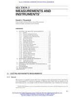
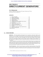
machine, and the dc field winding is located on the rotor, as illustrated schematically in Fig. 7-1. An
important exception is a special synchronous generator that is generally known as a brushless exciter.
A brushless exciter is a relatively small synchronous generator (50 to 500 kW) that is used to pro-
vide dc electric current to the rotating field winding of a large synchronous generator. In brushless
exciter, the dc field winding is mounted on the stator and the armature winding is mounted on the
rotor. That said, all further discussions of morphology in this section are based upon the most com-
mon arrangement for generators of 10 MW and above, where the ac armature winding is located on
the stator of the machine and the dc field winding is located on the rotor, as illustrated in Fig. 7-1.
In a generator, like that illustrated in Fig. 7-1, the magnetic circuit consists of a steel stator core
that is mounted upon the steel stator case and a steel rotor that is supported on bearings that are either
set into the case or separately mounted to the foundation. The coils of the armature winding are
mounted in the stator core, and the coils of the field winding are mounted on the rotor. Armature
winding electrical coils for generators of the type shown in Fig. 7-1 are typically deployed in radial
slots formed in the inner diameter of the stator, and field winding electrical coils are typically
deployed in radial slots formed in the outer diameter of the rotor, as illustrated in Figs. 7-2 and 7-3
respectively.
ALTERNATING-CURRENT GENERATORS 7-3
Stator case
End rings
End turns
Slip rings
Rotor
Seals
Bearings
Coupling
Field winding
Armature winding
Stator core
FIGURE 7-1 Elements of an ac generator.
Beaty_Sec07.qxd 17/7/06 8:32 PM Page 7-3
Downloaded from Digital Engineering Library @ McGraw-Hill (www.digitalengineeringlibrary.com)
Copyright © 2006 The McGraw-Hill Companies. All rights reserved.
Any use is subject to the Terms of Use as given at the website.
ALTERNATING-CURRENT GENERATORS
7-4 SECTION SEVEN
N
N
S
−a
2
−a
1
a
2
a
1
S
Stator coil
Magnetic
flux line
Air gap
Rotor coil
Stator coil
Rotor coil
Air gap
Stator
(laminated iron)
Rotor
(solid iron)
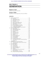
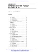
FIGURE 7-3 4-pole generator (left is round rotor, right is salient pole.
S
N
Stator coil
Rotor coil
Magnetic
flux line
Air gap
Stator
(laminated iron)
Rotor
(solid iron)
Rotor coil
Air gap
S
N
FIGURE 7-2 Round-rotor generator with two poles.
Beaty_Sec07.qxd 17/7/06 8:32 PM Page 7-4
Downloaded from Digital Engineering Library @ McGraw-Hill (www.digitalengineeringlibrary.com)
Copyright © 2006 The McGraw-Hill Companies. All rights reserved.
Any use is subject to the Terms of Use as given at the website.
ALTERNATING-CURRENT GENERATORS
7.2.2 Poles and Frequency
The rotor and stator (field and armature) of a synchronous machine must have the same number of
poles, as the magnetic interaction is between a succession of north-south magnetic-field pole pairs.
The number of pole pairs for a machine will be noted as p. The relationship between electrical fre-
quency f
e
and mechanical speed N is
(7-1)
where f
e
is measured in hertz (Hz) and N is in revolutions per minute (r/min). A common expression
for Eq. 7-1 is
(7-1a)
where P is number of poles (not number of pole pairs).
Synchronous generators are built in two elementary forms:
• Round-rotor machines are constructed with a rotor consisting of a cylinder of magnetic steel. In
modern generators, the cylinder is formed from a single forging of vacuum degassed steel. The
field winding is contained in radial slots in the surface of the rotor. Round-rotor machines usu-
ally have two or four poles as illustrated in Figs. 7-2 and 7-3 respectively. The diameter of the
rotor of a typical 25-MW generator is about 700 mm. The diameter of a 2000-MW generator can
approach 2 m.
• Salient-pole machines are constructed with a number of pole pieces mounted to a central rotor
shaft. The rotor pole pieces can be solid steel or assemblies of steel plates that are bound together
axially with bolts. The diameter of the rotor can range from less than 1 m in smaller salient pole
generators to nearly 20 m in the largest hydroelectric generators.
In both round-rotor and salient-pole generators, the magnetic flux passing through the rotors does
not vary in time, and the magnetic flux passing through the stator core does vary periodically in time
at the electrical line frequency. Consequently, the rotors can be made of solid steel, but the stator cores
must be made of thousands of thin layers of highly permeable electrical steel. Each layer of stator
core steel is coated with a thin layer of electrical insulation.
For electric utility operation, in which generation takes place at 50 or 60 Hz, mechanical speed is
inversely proportional to the number of poles. Thus, 2-pole machines, which turn at 3000 or 3600 r/min,
are used for most fossil-(fuel)-fired steam turbine generators which require high shaft speeds. Most
nuclear steam turbine generators, which have a lower shaft speed requirement, employ 4-pole designs and
therefore turn at 1500 or 1800 r/min. Turbine generators for both fossil and nuclear power plants are typ-
ically round-rotor designs.
Hydroelectric generators, which typically have much lower shaft speeds than turbine generators and
consequently require a large number of poles, are generally built as salient-pole machines. This is true
also for generators intended for operation with large reciprocating engines, such as medium-speed
diesels.
7.2.3 Basis of Operation
A synchronous generator works by causing an interaction of two multiple-pole magnetic-field dis-
tributions, those of the stator (armature) and, rotor (field). The interaction is said to be synchronous
because, if the rotor is turning at the speed described by Eq. (7-1), the armature and, rotor mag-
netic fields are turning at the same physical speed. The synchronous operation may be described
in two elementary ways, referred to as the magnetomotive force (mmf) method and the flux
method. These are described here, assuming a simple, linear, round-rotor model for the machine.
It should be noted that this model will, of necessity, be modified later to fully understand operation
of the machine.
N
#
P ϭ 120
#
f
e
f
e
ϭ p
N
60
ALTERNATING-CURRENT GENERATORS 7-5
Beaty_Sec07.qxd 17/7/06 8:32 PM Page 7-5
Downloaded from Digital Engineering Library @ McGraw-Hill (www.digitalengineeringlibrary.com)
Copyright © 2006 The McGraw-Hill Companies. All rights reserved.
Any use is subject to the Terms of Use as given at the website.
ALTERNATING-CURRENT GENERATORS
MMF Method. A principal feature of a synchronous generator is the mutual inductance between
phases. Assuming a 3-phase machine, the mutual inductances between the field winding and the 3-
phase windings are
(7-2)
(7-3)
(7-4)
where M is the peak value of mutual inductance and is the angle between the axes of the field
winding and the stator phase winding designated a. If it is further assumed that phase-phase induc-
tances, both self- and mutual, are not a function of rotor position, the use of energy methods gives a
simple expression for machine torque:
(7-5)
If the rotor turns at a constant angular velocity w/p ϭ 2f
e
/p, the field current is held constant at
a value of I
f
and the three stator currents are sinusoids in time, with the same amplitude and with
phases that differ by 120°
(7-6)
(7-7)
(7-8)
(7-9)
torque is
(7-10)
Note that torque is proportional to the product of the two current amplitudes and to the sine of
the phase angle between the current distributions. Further, the torque is acting in a direction so as to
align the two current distributions.
Flux Method. The flux method for estimating machine torque focuses on voltage (and hence flux)
induced in the machine stator. If L
a
is phase self-inductance and L
ab
is phase-phase mutual induc-
tance, flux linked by armature phase a is
(7-11)
Noting that the sum of phase currents is, under balanced conditions, zero and that the mutual
phase-phase inductances are equal, this is
(7-12)
where L
d
denotes synchronous inductance.
This flux is described by the equivalent circuit of Fig. 7-4, where
(7-13)
and d is the phase angle between internal voltage E
af
and terminal voltage V, and X
d
ϭ wL
d
.
Assume R
a
ϽϽ X
d
, where R
a
is the armature resistance.
E
af
ϭ jvMI
f
e
jd
l
a
ϭ (L
a
– L
ab
)i
a
ϩ MI
f
cos pu ϭ L
d
i
a
ϩ MI
f
cos pu
l
a
ϭ L
a
i
a
ϩ L
ab
I
b
ϩ L
ab
I
c
ϩ MI
f
cos p u
T ϭϪ
3
2
pMII
f
sin d
i
i
c
ϭ I cos avt ϩ
2p
3
b
i
b
ϭ I cos avt –
2p
3
b
i
a
ϭ I cos vt
pf ϭ vt ϩ d
i
T ϭ –pMi
a
i
f
sin pf – pMi
b
i
f
sin apf –
2p
3
b – pMi
c
i
f
sin apf ϩ
2p
3
b
M
cf
ϭ M cos apf ϩ
2p
3
b
M
bf
ϭ M cos apf Ϫ
2p
3
b
M
af
ϭ M cos pf
7-6 SECTION SEVEN
Beaty_Sec07.qxd 17/7/06 8:32 PM Page 7-6
Downloaded from Digital Engineering Library @ McGraw-Hill (www.digitalengineeringlibrary.com)
Copyright © 2006 The McGraw-Hill Companies. All rights reserved.
Any use is subject to the Terms of Use as given at the website.
ALTERNATING-CURRENT GENERATORS
ALTERNATING-CURRENT GENERATORS 7-7
d
q
V
E
af
j
иX
d
иI
g
I
g
(a) Overexcited (lagging power factor).
q
z
d
V
I
g
E
af
j и X
d
и I
g
(b) Underexcited (leading power factor).
FIGURE 7-5 Round-rotor synchronous generator.
If the generator is connected to a voltage source (i.e., if V is fixed), terminal current is
(7-14)
Real and reactive power into the terminals of phase a are
(7-15)
(7-16)
Considering all three phases, total generated power is
(7-17)
Phasor diagrams illustrating the operation of a round-rotor synchronous generator are shown in
Fig. 7-5. When the machine is overexcited, terminal current lags terminal voltage. When the gener-
ator is underexcited, terminal current leads terminal voltage.
7.2.4 Salient-Pole Machines: Two-Reaction Theory
Salient-pole generators, such as hydroelectric generators, have armature inductances that are a func-
tion of rotor position, making analysis one step more complicated. The key to analysis of such
P ϭϪ3P
a
ϭ
3
2
VE
af
X
d
sin d
Q
a
ϭ
1
2
V
2
X
d
Ϫ
1
2
VE
af
X
d
cos d
P
a
ϭϪ
1
2
VE
af
X
d
sin d
I ϭ
V – E
af
e
jd
jX
d
+
+
−
−
E
af
V
JX
d
R
a
I
A
FIGURE 7-4 Steady-state equivalent circuit (R
a
is
neglected for analysis).
Beaty_Sec07.qxd 17/7/06 8:32 PM Page 7-7
Downloaded from Digital Engineering Library @ McGraw-Hill (www.digitalengineeringlibrary.com)
Copyright © 2006 The McGraw-Hill Companies. All rights reserved.
Any use is subject to the Terms of Use as given at the website.
ALTERNATING-CURRENT GENERATORS
machines is to separate mmf and flux into two orthogonal com-
ponents. The two components are aligned with the direct axis and
the quadrature axis of the machine (Fig. 7-6). The direct axis is
aligned with the field winding, while the quadrature axis leads the
direct by 90°. Then, if is the angle between the direct axis and
the axis of phase a, flux linking phase a is
(7-18)
Then, in steady-state operation, if V
a
ϭ dλ
a
/dt and ϭ t ϩ d,
we obtain
(7-19)
or
(7-20)
(7-21)
One might think of the voltage vector as leading the flux vector by 90°. If the machine is linear,
fluxes are given by
(7-22)
(7-23)
Note that, in general, L
d
≠ L
q
, and for wound-field machines, L
d
Ͼ L
q
. Terminal voltage now has
these components
(7-24)
(7-25)
which is easily inverted to produce
(7-26)
(7-27)
where X
d
ϭ wL
d
, X
q
ϭ wL
q
, and E
af
ϭ wMI
f
.
In the complex frame of reference
(7-28)
(7-29)
complex power is, in the sense of a generator
(7-30)
or
(7-31)
(7-32)
Q ϭϪ
3
2
s
V
2
2
a
1
X
q
ϩ
1
X
d
b Ϫ
V
2
2
a
1
X
q
Ϫ
1
X
d
b cos 2d Ϫ
VE
af
X
d
cos dt
P ϭ
3
2
s
VE
af
X
d
sin d ϩ
V
2
2
a
1
X
q
Ϫ
1
X
d
b sin 2dt
P ϩ jQ ϭϪ
3
2
VI * ϭϪ
3
2
5(V
d
I
d
ϩ V
q
I
q
) ϩ j (V
q
I
d
Ϫ V
d
I
q
)6
I ϭ I
d
ϩ jI
q
V ϭ V
d
ϩ jV
q
I
q
ϭϪ
V sin
d
X
q
I
d
ϭ
V cos d Ϫ E
af
X
d
V
q
ϭ vl
d
ϭ vL
d
I
d
ϩ vMI
f
ϭ V cos d
V
d
ϭ –vl
q
ϭ –vL
q
I
q
ϭ V sin d
l
q
ϭ L
q
I
q
l
d
ϭ L
d
I
d
ϩ MI
f
V
q
ϭ vl
d
ϭ V cos d
V
d
ϭ –vl
q
ϭ V sin d
V
a
ϭ –vl
d
sin f – vl
q
cos f
l
a
ϭ l
d
cos f – l
q
sin f
7-8 SECTION SEVEN
FIGURE 7-6 Direct- and quadrature-
axis voltages.
Beaty_Sec07.qxd 17/7/06 8:32 PM Page 7-8
Downloaded from Digital Engineering Library @ McGraw-Hill (www.digitalengineeringlibrary.com)
Copyright © 2006 The McGraw-Hill Companies. All rights reserved.
Any use is subject to the Terms of Use as given at the website.
ALTERNATING-CURRENT GENERATORS
Figure 7-7 shows a phasor diagram for a machine with “positive” saliency (and ignoring stator
resistance). It is helpful to note that in such a machine, a vector with complex amplitude jI
X
q
begins
along the quadrature axis and ends at the ends of the terminal voltage vector.
7.2.5 Machine Size and Utilization
Generators produce torque through interaction between magnetic flux density and current over the
surface of the stator, and reaction torque through the same type of interaction over the surface of the
rotor. The stator and rotor face each other across the air gap. Power produced is
(7-33)
where torque produced is
(7-34)
where f ϭ electrical frequency, Hz
N ϭ mechanical speed, r/min
R ϭ stator inner radius
l ϭ active length
ϭaverage value of air gap shear stress, given approximately by
(7-35)
where B
1
is the peak value of fundamental magnetic flux density at the stator surface and K
z
is the
effective surface current density root mean square (rms) of the armature. The effective surface cur-
rent density is ampere-turns per unit of periphery, modified by pitch and distribution factors, and by
power factor.
s <
1
!2
B
1
K
z
T ϭ 2pR
2
ls
P ϭ v
mech
T ϭ 2p
f
p
T ϭ 2p
N
60
T
ALTERNATING-CURRENT GENERATORS 7-9
FIGURE 7-7 Vector diagram for salient-pole machine.
Beaty_Sec07.qxd 17/7/06 8:32 PM Page 7-9
Downloaded from Digital Engineering Library @ McGraw-Hill (www.digitalengineeringlibrary.com)
Copyright © 2006 The McGraw-Hill Companies. All rights reserved.
Any use is subject to the Terms of Use as given at the website.
ALTERNATING-CURRENT GENERATORS
7-10 SECTION SEVEN
FIGURE 7-9 Typical shear stress, high-speed generators.
Shear stress normally increases with pole pitch for a particular voltage and number of poles
because the deeper armature slots and greater field coil space allow more ampere-conductors per unit
of periphery. Typical shear stress levels for indirectly cooled, salient-pole generators are shown in
Fig. 7-8. Shear is higher for directly cooled machines and a consequence of increased current den-
sity, as shown in Fig. 7-9.
FIGURE 7-8 Typical shear stress, salient-pole, air-cooled generators.
Beaty_Sec07.qxd 17/7/06 8:32 PM Page 7-10
Downloaded from Digital Engineering Library @ McGraw-Hill (www.digitalengineeringlibrary.com)
Copyright © 2006 The McGraw-Hill Companies. All rights reserved.
Any use is subject to the Terms of Use as given at the website.
ALTERNATING-CURRENT GENERATORS
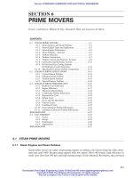
Another rough estimate of machine size employs the utilization factor:
(7-36)
where S is machine rating, D and l are outside diameter and length, respectively, and N is rotational speed.
Typical values for the utilization factor c are shown in Fig. 7-10. Here the utilization factor depends on
unit rating (high-speed machines) or unit rating per pole (low-speed machines) and on cooling.
7.3 ELECTROMAGNETICS
Sketches of the major elements of synchronous generators, together with field “flux forms,” are
shown in Figs. 7-11 and 7-12. Here the generator is “unrolled” and shown as if the air gap were flat.
Note that the main flux distribution air gap is not exactly sinusoidal. Thus the voltage produced will
contain time harmonics. Assign C
n
to be the amplitude of the nth-space harmonic of the flux density,
relative to the peak amplitude B
0
.
The fundamental flux per pole is
(7-37)
7.3.1 Generated Voltage
The rms amplitude of generated voltage is, for the time, fundamental
(7-38)
V
1
ϭ
1
!2
vN
a
k
w
⌽
1
⌽
1
ϭ
2RlB
0
C
1
p
c ϭ
S
D
2
lN
ALTERNATING-CURRENT GENERATORS 7-11
0
0
c ϭ f (S/2p)
c ϭ f (S )
a
b
Hydro
Turbo
500 1000 1500 S MVA2000
10
20
30
c
50
(kVA • min)/m
3
0102030S/2p MVA40
FIGURE 7-10 Utilization factors. (ABB.)
Beaty_Sec07.qxd 17/7/06 8:32 PM Page 7-11
Downloaded from Digital Engineering Library @ McGraw-Hill (www.digitalengineeringlibrary.com)
Copyright © 2006 The McGraw-Hill Companies. All rights reserved.
Any use is subject to the Terms of Use as given at the website.
ALTERNATING-CURRENT GENERATORS
7-12 SECTION SEVEN
FIGURE 7-11 (a) Generalized sketch of one pair of poles for a salient-pole
machine; (b) flux form for typical pair of poles (current in field winding only).
FIGURE 7-12 (a) Generalized sketch of one pair of poles for cylindrical
rotor machine; (b) flux form for a typical pair of poles (current in the field
winding only).
Beaty_Sec07.qxd 17/7/06 8:32 PM Page 7-12
Downloaded from Digital Engineering Library @ McGraw-Hill (www.digitalengineeringlibrary.com)
Copyright © 2006 The McGraw-Hill Companies. All rights reserved.
Any use is subject to the Terms of Use as given at the website.
ALTERNATING-CURRENT GENERATORS
ALTERNATING-CURRENT GENERATORS 7-13
where V
1
is the time fundamental voltage induced in a phase and N
a
is the number of turns in the
phase. In a 3-phase machine connected in wye, line-line voltage is times phase voltage. The
winding factor k
wn
is explained in Eqs. (7-40) through (7-42).
Harmonics. Time-harmonic voltages will be induced, and they are
(7-39)
It should be noted that certain time harmonics, those referred to as the triplen harmonics (odd
factors of 3), are induced in all three phases of a 3-phase machine in phase. Thus, if line-line volt-
age is measured, these harmonics (orders 3, 9, 15, . . .) will turn out to have zero amplitude.
Tooth Ripple Effects. The voltage waveform predicted in Eq. (7-39) neglects the effect of arma-
ture teeth and slots on the air-gap flux. The resulting modulations of the air-gap fields dc not gener-
ate voltages in armature conductors directly, rather induce currents in the field winding, any damper
windings that may exist, and in the rotor body itself and slot wedges. These currents produce flux
components, which in turn produce voltages in the armature winding. The orders of these voltages
are the integer multiple of the number of slots per pole pair, ±1. Thus, in a winding with 24 slots per
pole pair, the harmonics will have orders of 23, 25, 47, 49, 71, 73, and so on.
Estimation of voltage waveform is actually quite complex. While Eq. (7-39) may be used for a
first-order estimate, manufacturers of generators typically use numerical (finite element) methods for
prediction of harmonic voltage production in actual practice.
Load Effects. Load on the machine affects the harmonic content in the following ways:
1. Increased field current tends to increase all internal voltages including harmonics.
2. Armature reaction generally reduces the fundamental voltage more than the harmonics and,
through tooth and slot permeance variations, introduces additional harmonics.
3. Magnetic saturation changes harmonic magnitudes.
4. The fraction of harmonic internal voltage that appears at the machine terminals depends on the
relationship between internal and load impedance.
Voltage Waveform Standards. There are two ways of specifying the nonideal (departure from a
sine wave) nature of a voltage waveform. Both of these are defined in ANSI C42.10. Limiting
values for these factors are specified in ANSI C50.12, C50.13, and C50.14.
Deviation Factor. This is, as the name implies, the maximum deviation from a sine wave. It is
defined as the maximum difference between the actual waveform and the equivalent sine wave,
normalized to the equivalent sine wave amplitude.
Telephone Influence Factor. This is a weighted sum of the magnitudes of all harmonics in the
voltage waveform. The weighting of each harmonic is intended to reflect the relative objectional
effect of inductive coupling at each harmonic frequency on telephone communications.
Pitch and Breadth Factors. The winding factor is k
wn
ϭ k
pn
k
bn
k
sn
. Its component parts are called
the pitch factor
(7-40)
the breadth factor
(7-41)k
bn
ϭ
sin
mng
2
m sin
ng
2
k
pn
ϭ cos
na
2
V
n
ϭ V
1
C
n
C
1
k
wn
k
w
!3
Beaty_Sec07.qxd 17/7/06 8:32 PM Page 7-13
Downloaded from Digital Engineering Library @ McGraw-Hill (www.digitalengineeringlibrary.com)
Copyright © 2006 The McGraw-Hill Companies. All rights reserved.
Any use is subject to the Terms of Use as given at the website.
ALTERNATING-CURRENT GENERATORS
7-14 SECTION SEVEN
and, when applicable, the skew factor
where a ϭ pitch angle: the electrical angle between coil halves of the armature winding (this is
generally a bit less than to reduce the impact of higher harmonics and to make arma-
ture end windings shorter)
m ϭ number of slots per pole per phase
g ϭ electrical angle between slots
q
s
ϭ electrical angle of skew
Here, the relevant angles are stated in electrical terms. The electrical angle is p times the physical
angle. Thus, in a 4-pole machine with 72 slots, the electrical angle between slots is 2 × 360/72 ϭ 10°.
In many ac generators, the skew angle is zero for which the skew factor is unity. In some cases,
the stator is skewed with respect to the rotor (or vice versa) to reduce the effects of slot openings in
inducing currents in rotor parts with a consequent effect on rotor surface losses and noise.
7.3.2 Example of 4-Pole, Armature-Wound Machine
As an example, consider a 4-pole armature wound in 48 slots with a 5/6 relative pitch. The coil pitch,
or the number of slot pitches between coil halves, is then 10 slots (5/6 × 48/4). The number of
slots/pole/phase is 4 (48/[2 × 2 × 3]). Then the winding factors for the first few harmonics are
Observe that the winding factors k
w
for the harmonics 23 and 25 have the same value as the funda-
mental voltage. This is so for all harmonics whose numbers are equal to (integer multiple of number
of slots per pair of poles) ±1. These harmonics are called slot harmonics, and the armature winding
cannot attenuate the voltages induced by flux waves of these orders.
7.3.3 Armature Reaction
Current in the armature conductors produces an mmf which has the same number of poles as the field
structure. The fundamental harmonic of this mmf rotates at synchronous speed, and adds to the field
mmf in a vector sense as shown in Fig. 7-13. For generators supplying reactive current to an induc-
tive load, the net effect of the armature reaction is to oppose the field mmf, requiring additional field
current to sustain flux.
Harmonic k
p
k
d
k
w
1 0.9659 0.9577 0.9250
5 0.2588 0.2053 0.0531
7 0.2588 −0.1576 −0.0408
11 0.9659 −0.1261 −0.1218
13 −0.9659 0.1261 −0.1218
17 −0.2588 0.1576 −0.0408
19 −0.2588 −0.2053 0.0531
23 −0.9659 −0.9577 0.9250
25 0.9659 −0.9577 −0.9250
29 0.2588 −0.2053 −0.0531
31 0.2588 0.1576 0.0408
35 0.9659 0.1261 0.1218
37 −0.9659 −0.1261 0.1218
k
bn
ϭ
sin
nu
s
2
nu
s
2
Beaty_Sec07.qxd 17/7/06 8:32 PM Page 7-14
Downloaded from Digital Engineering Library @ McGraw-Hill (www.digitalengineeringlibrary.com)
Copyright © 2006 The McGraw-Hill Companies. All rights reserved.
Any use is subject to the Terms of Use as given at the website.
ALTERNATING-CURRENT GENERATORS
The peak value of the space fundamental of armature reaction current for a 3-phase machine is
(7-43)
where I is rms terminal current, N
a
is the number of series turns per phase, and the winding factors
are as defined above.
Space harmonic components of armature reaction current can produce losses in the rotor as they
turn asynchronously. The magnitude of the harmonic mmf of order n is
(7-44)
The rotational speed of each of these harmonics is
(7-45)
where, for a 3-phase machine, the rotational direction is same as that of the fundamental (positive)
for harmonics of orders 7, 13, 19,… , and is opposite from the rotation of the fundamental (nega-
tive) for harmonics of orders 5, 11, 17, … . The electrical frequency of the pairs of these waves in
the rotor frame turns out to coincide, so that the armature harmonics of orders 5 and 7 and funda-
mental frequency both appear in the rotor frame at 6 times the fundamental frequency.
7.3.4 Magnetic Circuit and Material
The magnetic circuit of an ac generator, as with other electric machines, is made up of the air gap,
the stator teeth and backiron, the rotor poles, and the shaft section. Each of these elements has an
effect on machine rating and operation.
The function of the magnetic circuit is to carry flux that links the armature conductors to produce
voltage.
v
n
ϭ m
1
n
#
v
F
an
ϭ
3
2
4
np
!2
N
a
Ik
pn
k
bn
k
sn
F
a
ϭ
3
2
4
p
!2
N
a
Ik
p
k
b
k
s
ALTERNATING-CURRENT GENERATORS 7-15
FIGURE 7-13 Armature reaction (vector analysis of magnetic fields).
Beaty_Sec07.qxd 17/7/06 8:32 PM Page 7-15
Downloaded from Digital Engineering Library @ McGraw-Hill (www.digitalengineeringlibrary.com)
Copyright © 2006 The McGraw-Hill Companies. All rights reserved.
Any use is subject to the Terms of Use as given at the website.
ALTERNATING-CURRENT GENERATORS
Air gap. The air gap constitutes the division between the rotating part of the machine—the rotor,
which carries the field winding—and the stationary part of the machine—the stator, which carries
the armature winding. In ac generators, the air-gap dimension is determined by the electrical char-
acteristics of the machine. There is a trade-off between excitation mmf (toward a small air-gap
dimension) and armature reaction flux (toward a large air-gap dimension). This trade-off generally
results in an air gap, which is substantially larger than mechanical considerations such as machining
tolerances or windage loss would dictate.
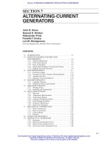
Stator Teeth and Backiron. The armature magnetic circuit carries alternating flux and is always
laminated, either with complete ring laminations (for small machines) or with overlapping segmented
laminations. The material most commonly used is sheet steel, of an alloy containing about 3.5% sil-
icon, in sheets of thickness between about 0.35 and 0.65 mm. Grain-oriented steel, with reduced
losses and improved permeability in the direction of rolling, is often used in large turbogenerators.
Orientation in the circumferential direction is advantageous in such machines because of the large
proportion of steel and moderate flux densities in the backiron. At high flux densities characteristic
of the armature teeth, the advantage of grain orientation becomes less pronounced.
The active region of the armature constitutes the alternation of stator teeth and slots carrying the
armature winding. The division between teeth and slots is a compromise between flux-carrying capa-
bility and current-carrying capability. The trade-off generally results in a division that is about half
slots and half teeth. Flux densities in the stator teeth are usually high enough to result in moderate
saturation of the magnetic material.
Rotor Iron. The magnetic flux in the rotor is nearly constant, varying in the main only slightly with
changes in load and terminal voltage and with small higher frequency components due to time and
space harmonics of armature flux. This allows the rotor magnetic circuit to be made of solid steel.
In turbine generators, the rotor is typically made of a single-piece forging of steel with slots for
the field winding cut by machining. The losses caused by harmonic driven eddy currents in the solid
steel pole faces can be problematic, and are reduced by making the air gap larger, by increasing the
number of stator slots and, by choosing a suitable (short-pitch) coil throw for the armature.
7-16 SECTION SEVEN
FIGURE 7-14 Magnetization curves of commonly used steels.
Beaty_Sec07.qxd 17/7/06 8:32 PM Page 7-16
Downloaded from Digital Engineering Library @ McGraw-Hill (www.digitalengineeringlibrary.com)
Copyright © 2006 The McGraw-Hill Companies. All rights reserved.
Any use is subject to the Terms of Use as given at the website.
ALTERNATING-CURRENT GENERATORS
Salient-pole machines may have solid or laminated poles. In many cases, laminated poles are neces-
sary to control eddy current losses. Pole laminations are commonly made of low carbon steel, 1.5 to 2 mm
thick. Thinner steel, sometimes with silicon content, may be used where further control of eddy current
losses is required. The shaft, or inner portion of the rotor of salient-pole machines, is often a solid forg-
ing, or in large machines such as hydroelectric generators may be fabricated from structural steel pieces.
Magnetic Materials. Typical magnetization characteristics of steel materials used in the magnetic
circuit of ac generators are shown in Fig. 7-14.
7.4 MACHINE OPERATION
In normal operation, real power is dictated by the prime mover and reactive power is determined by
the real power and by field current.
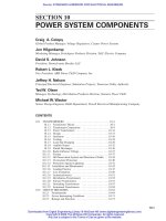
7.4.1 Capability Diagram
Equations (7-31) and (7-32) are approximate ways of estimating the real and reactive power output
of a generator as a function of field current and torque angle. (Eq. 7-46 is provided for additional
clarification.) If these are cross-plotted as shown in Fig. 7.14, a way of representing the capability of
an ac generator emerges as shown in Fig. 7-15. This is called a capability chart for obvious reasons
and four limits are shown.
(7-46)
The final capability curve is shown in Fig. 7-16. Four limits are shown on this chart:
1. The field winding limit is generally related to the thermal capability of the field winding, and lim-
its operation of the generator at high reactive power conditions.
2. The armature winding limit is generally related to the thermal capability of the armature winding,
and is typically a limit on total kVA (kilovoltampere) output of the machine.
3. The stability limit is related to torque angles that are nearly at the peak of the torque-angle curve
(90° for round-rotor machines).
4. Often, the configuration of magnetic flux is such that, at high reactive power absorption (negative Q),
there is axial flux in the core ends, leading to excessive heating and limiting the reactive power
that can be absorbed by the machine.
Very often the prime-mover power rating is plotted on the capability chart. It is, of course, a line
of constant real power. The heating related limits (armature, field, and core end) may be functions of
the state of the cooling system of the machine, such as hydrogen pressure. (See Sec. 7.10 on cooling.)
7.4.2 Saturation Curves and Excitation
Alternating-current generators are usually operated with at least part of the magnetic circuit partially
saturated, so that the linear model of machine operation implied by some of the foregoing discussion
does not give exactly the right answers. What follows is an approximate way of estimating excitation
requirements for an ac generator.
It should be noted that numerical methods, employing finite elements, are now available and
capable of making even more accurate estimates of machine performance including excitation
Q ϭ a
3
#
V
f
X
s
b
#
X
S
#
I
A
sin(u
z
) ϭ 3
#
V
f
#
I
A
sin(u
Z
)
P ϭ 3
#
V
f
#
I
A
#
cos(u
z
) ϭ 3
#
V
f
a
E
A
#
sin(d)
X
s
b
ALTERNATING-CURRENT GENERATORS 7-17
Beaty_Sec07.qxd 18/7/06 4:16 PM Page 7-17
Downloaded from Digital Engineering Library @ McGraw-Hill (www.digitalengineeringlibrary.com)
Copyright © 2006 The McGraw-Hill Companies. All rights reserved.
Any use is subject to the Terms of Use as given at the website.
ALTERNATING-CURRENT GENERATORS
7-18 SECTION SEVEN
q
z
X
s
и I
A
и cos(q
z
)
X
s
и I
A
и sin(q
z
)
=
E
A
и sin δ
Volts (
x-axis)
d
q
z
E
A
Volts (y-axis)
jX
S
I
A
I
A
−V
f
V
f
0
E
A
и sin d
X
S
Note: I
A
cos (q
z
) =
(a) Developing the capability curve from the phasor diagram.
q
z
Q = (3 и ) и [X
s
и I
A
и sin (q
z
)]
kVARS
d
q
z
V
f
V
f
X
S
S = (3 и ) и X
s
и I
A
V
f
X
S
Q = (3 и ) и (−V
f
)
V
f
X
S
(3 и ) и E
A
V
f
X
S
P = (3 и ) и [X
s
и I
A
и cos (q
z
)]
V
f
X
S
S
kW
(b) Relating Power and Reactive Power to the phasor diagram.
Rotor current limit
Stator current limit
P, kW
3 и
Q, kVARS
E
A
V
f
X
S
Q = −3 и
V
f
2
X
S
P
S
Q
θ
z
(c) Relating the phasor diagram to the capability curve.
FIGURE 7-15 Estimating the real and reactive power of a generator as a function of field
current and torque angle.
Beaty_Sec07.qxd 17/7/06 8:32 PM Page 7-18
Downloaded from Digital Engineering Library @ McGraw-Hill (www.digitalengineeringlibrary.com)
Copyright © 2006 The McGraw-Hill Companies. All rights reserved.
Any use is subject to the Terms of Use as given at the website.
ALTERNATING-CURRENT GENERATORS
requirements. When these more sophisticated methods are available, it is generally better to use
them. The approximate method described here is included for two reasons: (1) because it may aid in
a physical understanding of generator operations and (2) because it gives reasonably accurate
answers without the need for a large number of computer “cycles.”
Figure 7-17 shows open- and short-circuit characteristic curves for an ac generator. These curves
are taken with the generator operating at rated speed. Important curves are
1. The air gap line is the extrapolation of open-circuit voltage versus field current at low levels of
field current.
2. The no-load saturation curve is the actual open-circuit voltage versus field current characteristic.
3. The short-circuit saturation curve typically does not show saturation. It represents a measurement
of current in the terminals of the generator, with the terminals short-circuited, versus field current.
4. The rated current, zero power factor saturation curve shows voltage at the terminals of the
machine versus field current if the machine is operated with rated armature current at zero power
factor.
Calculating Excitation Requirement. Field current required for machine operation consists of
three parts
(7-47)
where, I
FG
is the field current required to excite the air gap, I
FSI
is the field current required to com-
pensate for direct-axis armature current, and I
FS
is the field current required to compensate for satu-
ration. Note that this method does not account for saturation of the quadrature axis. Armature
resistance is generally neglected.
Addition of the three components of current is shown in Fig. 7-18. In this figure, the field current
that compensates for armature reaction is added at the power factor angle Θ. The current I
FS
is the cur-
rent required to compensate for direct axis saturation. I
FS
is the distance from the air-gap line to the no-
load saturation curve at the voltage corresponding to the flux level in the magnetic circuit. This voltage
is referred to as the voltage behind Potier reactance. It is estimated as shown in Fig. 7-19.
To find the (fictitious) Potier reactance, refer back to Fig. 7-17. Note that for the zero power fac-
tor test, all the fluxes are on the direct axis, so they add directly. Two of the current components, I
FG
and I
FSI
, are easily determined. The difference between field current for the zero power factor test
and the sum of these two currents is I
FS
. Since this corresponds to the distance between the air-gap
I
f
ϭ I
FG
ϩ I
FSI
ϩ I
FS
ALTERNATING-CURRENT GENERATORS 7-19
Stator winding limit
Field winding limit
Prime mover limit
Stability limit
End packet heating limit
P
Q
d
FIGURE 7-16 Capability diagram, round-rotor machine.
Beaty_Sec07.qxd 18/7/06 4:16 PM Page 7-19
Downloaded from Digital Engineering Library @ McGraw-Hill (www.digitalengineeringlibrary.com)
Copyright © 2006 The McGraw-Hill Companies. All rights reserved.
Any use is subject to the Terms of Use as given at the website.
ALTERNATING-CURRENT GENERATORS
7-20 SECTION SEVEN
FIGURE 7-17 Typical saturation curves of an ac generator showing graphic determination of Potier
reactance (quantities are in per unit values).
FIGURE 7-18 ANSI method of calculating load excitation.
line and saturation curve at the voltage behind Potier reactance, it determines that voltage. For the
zero power factor test, I
a
x
p
is a vertical line of length x
p
since I
a
ϭ 1. The distance between the sat-
uration curve and air-gap line is the same as I
FS
at a voltage found by casting a line parallel to the
air-gap line from I
F
− I
FSI
. This is ab on Fig. 7-17. Then x
p
corresponds to bc on the same figure.
FIGURE 7-19 Calculation of voltage behind Potier reactance.
Beaty_Sec07.qxd 17/7/06 8:32 PM Page 7-20
Downloaded from Digital Engineering Library @ McGraw-Hill (www.digitalengineeringlibrary.com)
Copyright © 2006 The McGraw-Hill Companies. All rights reserved.
Any use is subject to the Terms of Use as given at the website.
ALTERNATING-CURRENT GENERATORS
7.5 ARMATURE WINDINGS
A wide variety of winding types may be used to produce a desired voltage with the desired number
of phases and a suitable waveshape. In small generators, “scramble wound” armature windings may
be used. However, in most alternator applications, double-layer, form-wound coils in open slots with
60° phase belts are used. In such a winding, each slot has two conductor bars (often called half-
coils), not necessarily from the same phase winding. These bars are insulated from ground and
secured in the slot, usually by wedges. It is usually necessary for the bar to have the ability to slide
axially in the slot to accommodate thermal expansion, but it must not be loose in either the radial or
azimuthal directions. This has led to a number of proprietary techniques for armature construction.
7.5.1 Winding Forms
Figure 7-20 shows an example winding diagram. For the purposes of this figure, the machine is
shown “rolled out flat,” with the dotted lines on either side representing the same azimuthal location.
In this case, the machine has 24 slots, each with two half-coils, as shown in the slot allocation sec-
tion of the drawing, at the bottom of the figure. The upper part of the figure shows how one phase
of the winding would be laid out. This drawing shows a lap type winding (the most commonly used)
with a
5
/
6
pitch. In a 24-slot, 2-pole winding a full-pitch coil would span 12 slots, while in the
5
/
6
pitch
winding the coils span 10 slots.
Fractional Slot Windings. Fractional slot windings, in which the number of slots per pole per
phase is not an integer, have coil groups that differ from one another. These can be arranged to pro-
duce balanced voltages under circumstances that are beyond the scope of this discussion.
7.5.2 Stranding and Transposition
At power frequencies (50 or 60 Hz), the skin depth in copper is on the order of 1 cm so that it is usu-
ally necessary to subdivide armature conductors into a number of parallel strands. In form-wound
ALTERNATING-CURRENT GENERATORS 7-21
Terminals
End turns
End turns
Upper
Lower
Slot allocation
Straight
section
Slots TeethPhase A winding
AAAABBBBCCCCAAAABBBBCCCC
CCAAAABBBBCCCCAAAABBBBCC
FIGURE 7-20 Armature in 24 slots, 5/16 pitch.
Beaty_Sec07.qxd 17/7/06 8:32 PM Page 7-21
Downloaded from Digital Engineering Library @ McGraw-Hill (www.digitalengineeringlibrary.com)
Copyright © 2006 The McGraw-Hill Companies. All rights reserved.
Any use is subject to the Terms of Use as given at the website.
ALTERNATING-CURRENT GENERATORS
coils, these strands are usually rectangular to allow for good space factor. To prevent circulating cur-
rents between parallel strands, it is necessary to employ transposition to ensure that voltages induced
in each strand are approximately the same.
The simplest form of transposition, often used in transformers and sometimes in generators, is to
twist the armature conductors at 180° in the end turns. Or sometimes, groups of conductors are con-
nected together in the end turns with a progressive transposition that constitutes a “twist” of the
winding from half-coil to half-coil.
Transposition of strands in the end turns is generally not satisfactory in large ac generators. A
transposition scheme attributed to Roebel is usually used (see Fig. 7-21). The Roebel transposition
is equivalent to a twist of the conductors in the slot. It is usual to carry out the Roebel transposition
only within the slot part of the winding. A variety of transpositions are used, including 180°, 360°,
and 540°. The first two are effective only at eliminating circulating currents due to flux crossing the
slot, but do not compensate for flux in the end windings. The 540° transposition, attributed to
Ringland and Rosenberg (1959) is often applied because it filters out most of the circulating currents
in a bar. Other more complex Roebel transposition arrangements that more extensively filter out cir-
culating currents are possible but are rarely used because of manufacturing complexity. Bapat (1973)
and Neidhoeffer (1990) outline general surveys about special transpositions.
7.6 INSULATION SYSTEMS
Electrical insulation is used to isolate field conductors from each other and ground, and in the arma-
ture winding to isolate strands and turns from each other and the whole winding from ground. Proper
application of electrical insulation constitutes much of the art of ac machine design, particularly in
the larger generator sizes.
7.6.1 Materials
International standards have established various classes of insulation systems based primarily on the
maximum steady-state operating temperature and have established voltage proof tests to demonstrate
the dielectric capability of insulation systems.
Of the several thermal classes of insulation systems, three are most applicable to ac generators.
These are Classes 130, 155, and 180. Class 105 insulation materials are no longer used in modern
7-22 SECTION SEVEN
FIGURE 7-21 Illustration of Roebel transposition: (a) typical offset
conductor strand; (b) group of conductor strands composing half the
conductor; (c) complementary group; (d) assembly.
Beaty_Sec07.qxd 17/7/06 8:32 PM Page 7-22
Downloaded from Digital Engineering Library @ McGraw-Hill (www.digitalengineeringlibrary.com)
Copyright © 2006 The McGraw-Hill Companies. All rights reserved.
Any use is subject to the Terms of Use as given at the website.
ALTERNATING-CURRENT GENERATORS
ac generators. In the most recent revisions of IEEE C50-12 and C50-13, and IEC 60034-1 and
60034-3 standards for ac generators, the numerical classifications 130, 155, and 180 have been sub-
stituted for the previously used alphabetical classifications B, F, and H, respectively.
Class 130 systems comprise inorganic materials such as mica and glass fibers, organic materials
such as synthetic films, and suitable binders. Until recently, Class 130 systems have been identi-
fied as Class B systems.
Class 155 systems comprise generally similar materials with binders capable of higher tempera-
tures. Until recently, Class 155 systems have been identified as Class F systems.
Class 180 systems include silicone elastomers as well as mica, glass fibers, and higher-temperature
binders. Until recently, Class 180 systems have been identified as Class H systems.
Synthetic chemistry has presented a continued flow of materials suitable for electrical insulation,
and any of the above-mentioned insulation systems may be supplemented by new materials.
7.6.2 Temperature Measurements
Several methods of observing winding temperatures are used. Note that it is ordinarily not practical
to actually measure the “hot spot” temperature directly, so that an allowance is normally given, based
on the method of temperature measurement used.
Thermometer method. A thermometer (mercury filled, or other suitable temperature measuring
device) may be applied to what is expected to be the hottest part accessible. Of the several methods
described, this one gives readings furthest from the maximum winding temperature and therefore has
the highest hotspot allowance.
Resistance method. The resistance of electrical conductors is a function of temperature. Thus, if
the resistance of the winding can be measured and its resistance at a reference temperature is known,
the average temperature of the winding may be calculated
(7-48)
where R
1
is the resistance at temperature T
1
and R
2
is the resistance at temperature T
2
. The constant
K is 234.5°C for copper, 242°C for silver-alloyed copper used for hollow conductors, and 225°C for
electrical conductivity aluminum.
Discharge coolant method. For directly cooled armature windings in the largest generators, the
observable temperature is the coolant being discharged from the armature coils.
Embedded detector method. Thermocouples or resistive thermal detectors are built into the
machine. In the most common application these are placed between the coil sides in a two-layer
armature winding near the axial center or warmest region of the core.
Applied thermocouple method. Thermocouples are applied directly to the conductors, with little
or no insulation. This method is used only for experimental testing to, for example, determine hot-
spot allowances. It is not used for operational measurements.
7.6.3 Temperature Ratings
Temperature ratings of ac generator windings are based on measurements of winding temperatures
and the thermal class of insulation used. These measurements are specified in IEEE C50-12 and
C50-13, and IEC 60034-1. Generally, machines with smaller ratings employ the resistance method
and larger machines employ embedded detectors or discharge coolant measurement methods.
T
2
ϭ K ϩ
R
2
R
1
#
(1 ϩ T
1
)
ALTERNATING-CURRENT GENERATORS 7-23
Beaty_Sec07.qxd 17/7/06 8:32 PM Page 7-23
Downloaded from Digital Engineering Library @ McGraw-Hill (www.digitalengineeringlibrary.com)
Copyright © 2006 The McGraw-Hill Companies. All rights reserved.
Any use is subject to the Terms of Use as given at the website.
ALTERNATING-CURRENT GENERATORS
7-24 SECTION SEVEN
7.6.4 Armature-Winding Insulation
Armature voltages range from about 220 V to about 27 kV. With such a wide range, different tech-
niques are employed. In the armature, insulation is for strands, turns, and ground wall.
Strand insulation is required to prevent circulating currents within a conductor bar. The voltage
levels are not high so mechanical integrity is the important feature of strand insulation. This is usu-
ally a layer of served fabric or film coating.
Turn insulation is used in multiturn coils, generally applicable only in small-size generators. This
insulation is required to withstand turn-turn voltage, although in some cases large transient spikes of
voltage may be incident on the winding.
Ground wall insulation must withstand full voltage to ground. Typically, the whole of an arma-
ture winding is insulated for full voltage, even though some of the coils, located near the neutral end
of the winding, see lesser voltage.
In high-voltage armatures (above ~5 kV), some measures must be taken to control the effects of
corona and partial discharge. In the slot portion of the coil, it is necessary to prevent discharges due
to capacitive coupling through the insulation, from the surface of the insulation to the grounded sta-
tor core. These discharges are prevented by coating the outer surface of the insulated conductor with
a conductive (sometimes called semiconducting) coating (paint or tape). To prevent discharges along
the surface of the conductors in the end windings, those sections are sometimes coated with very
weakly conducting coatings that are called grading coatings (paint of tape).
It is important to prevent electrical discharges in the vicinity of the winding because such dis-
charges through air and in the presence of any water vapor will produce nitrous and nitric acid and
ozone, substances corrosive to the materials of the winding.
7.6.5 Field-Winding Insulation
Field windings operate at much lower voltages (usually less than ~800 V). Some transient conditions,
such as interruption of field current, can lead to much higher voltages.
Field windings are subject to the centrifugal forces due to rotation, and this presents special chal-
lenges. Dimensional stability is required of the field winding to prevent dynamic rotor imbalance. It
is also necessary, in larger machines, to allow the field winding to expand thermally with respect to
the rotor steel. The resulting “creepage” surfaces must allow slip in the axial direction but not move-
ment in the other directions.
7.6.6 Insulation Maintenance
Failure of the insulation system of a generator produces a prompt outage of the generator. This pro-
duces ample reason to maintain the insulation system in good order. Insulation maintenance
involves measures to reduce or eliminate sources of abnormal aging and damage to insulation,
inspection to determine if deterioration has taken place, and testing to assess the state of the insu-
lation system.
Service Conditions. Some operational conditions that produce accelerated insulation deterioration
and ways of controlling them are described as follows:
Excessive temperature may be caused by blockage of ventilation paths or cooling tubes or by
overload. Measurement of winding temperature is used to detect overtemperature conditions to
allow the cause to be corrected.
Excessive voltage may be caused by control errors, but is usually the result of switching opera-
tions or lightning. This is usually a matter for correct system design to prevent such overvoltages.
Contamination can affect windings in one of the three ways. Some contaminants may attack
insulation system, reducing its dielectric strength or affecting its mechanical properties. Some
contaminants may thermally insulate parts, causing excessive temperatures. On the other hand,
some contaminants such as conducting particles may lead to abnormal potential distribution and
Beaty_Sec07.qxd 17/7/06 8:32 PM Page 7-24
Downloaded from Digital Engineering Library @ McGraw-Hill (www.digitalengineeringlibrary.com)
Copyright © 2006 The McGraw-Hill Companies. All rights reserved.
Any use is subject to the Terms of Use as given at the website.
ALTERNATING-CURRENT GENERATORS
excessive voltage stresses. Control of contamination consists of preventing substances from
entering the generator (if possible) and of inspecting periodically for signs of contamination or
related damage.
Physical damage to insulation can occur for a variety of reasons, including vibration, overspeed,
short-circuit forces or improper synchronization, and even damage by foreign objects. Generally,
prevention and inspection are used to control such damage.
Corona, an electrical discharge around the surface of stator insulation, may be caused by conta-
mination or by some inherent weakness in the insulation system itself.
Inspection. Visual inspection supplemented with simple physical tests may be carried out to diag-
nose incipient problems that might lead to eventual insulation failure. Some symptoms are described
as follows:
Swelling or shrinking is evident from visual inspection, probing, and tapping on the insulation.
Swelling is accompanied by reduction in physical integrity and sometimes by separation of insu-
lation from the underlying conductor. Shrinkage leads to looseness in the slot.
Cracking results from abnormal mechanical stress or poor winding support. Girth cracking is dis-
placement of insulation near the core ends of relatively large machines, caused by thermal
cycling.
Substances noted on the winding can include contaminants such as oil, dust, and water and also
deposits produced by corona, which may be white, gray, or red and may appear in regions of high
electrical stress.
Slot wedges and fillers may become loose in service. This will lead to deterioration if not cor-
rected, so any inspection of a generator should include checking of all the stator slot wedges.
Tests of Insulation Systems. Before commissioning a new generator and as part of generator main-
tenance programs, tests of insulation systems are carried out. There is a wealth of literature on this
topic cited in the references. What appears here is only a first-order synopsis.
Testing of insulation systems in ac generators is used to uncover existing weaknesses or faults
and to produce an indication of expected service reliability.
Some tests commonly employed are described as follows:
Insulation resistance is a straightforward test used to indicate the existence of contamination or
moisture absorption. It seldom indicates the existence of an incipient fault. It is difficult to assign
specific acceptable values for the results of insulation resistance tests, but it is possible to ‘trend’
the results of such tests.
Dielectric absorption tests are similar to a dc resistance test. A voltage in the range of 500 V to
5 kV is placed across the insulation and current is measured as a function of time. The apparent
resistance is the ratio of voltage to current and is a function of time. The polarization index is the
ratio of the value of this apparent resistance after 10 to the value after 1 min. The polarization
index may be used for trending. Generally, for Class 130 and Class 155 insulation, a polarization
index of about 2 or greater is an indication of a healthy winding, while a value of 1 or less is an
indicator of potential trouble. Further description of resistance and dielectric absorption tests is
contained in IEEE Standard 43.
Overvoltage tests are proof tests. Failure of an overvoltage test (called also high potential or hi-pot)
is destructive. Such tests are carried out because failure of an insulation system under test con-
ditions is much less damaging than failure in service. Overvoltage tests may be carried out with
either ac or dc voltage, and employ voltage levels that are selected for the particular test. New
windings (whether in a new generator or in a newly rewound generator) are typically tested to
higher levels relative to their operating voltage, than are older windings that have been in ser-
vice for a significant portion of their expected life. Typical values of high potential for testing
new windings are twice operating line to line voltage plus 1000 V. Typical values of high poten-
tial for testing mature windings are between 125% and 150% of operating line to line voltage.
ALTERNATING-CURRENT GENERATORS 7-25
Beaty_Sec07.qxd 17/7/06 8:32 PM Page 7-25
Downloaded from Digital Engineering Library @ McGraw-Hill (www.digitalengineeringlibrary.com)
Copyright © 2006 The McGraw-Hill Companies. All rights reserved.
Any use is subject to the Terms of Use as given at the website.
ALTERNATING-CURRENT GENERATORS