handbook for electrical engineers hu (7)
Bạn đang xem bản rút gọn của tài liệu. Xem và tải ngay bản đầy đủ của tài liệu tại đây (1.05 MB, 42 trang )
SECTION 8
DIRECT-CURRENT GENERATORS
O. A. Mohammed
Professor, Department of Electrical and Computer Engineering, Florida
International University Miami, FL
CONTENTS
8.1 THE DC MACHINE . . . . . . . . . . . . . . . . . . . . . . . . . . . . . . .8-1
8.2 GENERAL PRINCIPLES . . . . . . . . . . . . . . . . . . . . . . . . . . .8-3
8.3 ARMATURE WINDINGS . . . . . . . . . . . . . . . . . . . . . . . . . .8-5
8.4 ARMATURE REACTIONS . . . . . . . . . . . . . . . . . . . . . . . . .8-8
8.5 COMMUTATION . . . . . . . . . . . . . . . . . . . . . . . . . . . . . . . .8-10
8.6 ARMATURE DESIGN . . . . . . . . . . . . . . . . . . . . . . . . . . . .8-19
8.7 COMPENSATING AND COMMUTATING FIELDS . . . . .8-22
8.8 MAGNETIC CALCULATIONS . . . . . . . . . . . . . . . . . . . . .8-23
8.9 MAIN FIELDS . . . . . . . . . . . . . . . . . . . . . . . . . . . . . . . . . .8-28
8.10 COOLING AND VENTILATION . . . . . . . . . . . . . . . . . . . .8-30
8.11 LOSSES AND EFFICIENCY . . . . . . . . . . . . . . . . . . . . . . .8-32
8.12 GENERATOR CHARACTERISTICS . . . . . . . . . . . . . . . . .8-34
8.13 TESTING . . . . . . . . . . . . . . . . . . . . . . . . . . . . . . . . . . . . . .8-36
8.14 GENERATOR OPERATION AND MAINTENANCE . . . . .8-36
8.15 SPECIAL GENERATORS . . . . . . . . . . . . . . . . . . . . . . . . .8-39
BIBLIOGRAPHY . . . . . . . . . . . . . . . . . . . . . . . . . . . . . . . . . . . . . .8-40
8.1 THE DC MACHINE
Applications. The most important role played by the dc generator is the power supply for the
important dc motor. It supplies essentially ripple-free power and precisely held voltage at any desired
value from zero to rated. This is truly dc power, and it permits the best possible commutation on the
motor because it is free of the severe waveshapes of dc power from rectifiers. It has excellent
response and is particularly suitable for precise output control by feedback control regulators. It is
also well suited for supplying accurately controlled and responsive excitation power for both ac and
dc machines.
The dc motor plays an ever-increasing vital part in modern industry, because it can operate at and
maintain accurately any speed from zero to its top rating. For example, high-speed multistand steel
mills for thin steel would not be possible without dc motors. Each stand must be held precisely at an
exact speed which is higher than that of the preceding stand to suit the reduction in thickness of the
steel in that stand and to maintain the proper tension in the steel between stands.
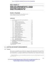
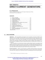
General Construction. Figure 8-1 shows the parts of a medium or large dc generator. All sizes differ
from ac machines in having a commutator and the armature on the rotor. They also have salient poles
on the stator, and, except for a few small ones, they have commutating poles between the main poles.
8-1
Former contributors include Thomas W. Nehl and E. H. Myers.
Beaty_Sec08.qxd 17/7/06 8:34 PM Page 8-1
Downloaded from Digital Engineering Library @ McGraw-Hill (www.digitalengineeringlibrary.com)
Copyright © 2006 The McGraw-Hill Companies. All rights reserved.
Any use is subject to the Terms of Use as given at the website.
Source: STANDARD HANDBOOK FOR ELECTRICAL ENGINEERS
Construction and Size. Small dc machines have large surface-to-volume ratios and short paths for
heat to reach dissipating surfaces. Cooling requires little more than means to blow air over the rotor
and between the poles. Rotor punchings are mounted solidly on the shaft, with no air passages
through them.
Larger units, with longer, deeper cores, use the same construction, but with longitudinal holes
through the core punchings for cooling air.
Medium and large machines must have large heat-dissipation surfaces and effectively placed
cooling air, or “hot spots” will develop. Their core punchings are mounted on arms to permit large
volumes of cool air to reach the many core ventilation ducts and also the ventilation spaces between
the coil end extensions.
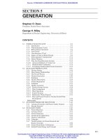
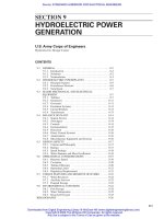
Design Components. Armature-core punchings are usually of
high-permeability electrical sheet steel, 0.017 to 0.025 in thick, and
have an insulating film between them. Small and medium units use
“doughnut” circular punchings, but large units, above about 45 inches
in diameter, use segmental punchings shaped as shown in Fig. 8-2,
which also shows the fingers used to form the ventilating ducts.
Main- and commutating-pole punchings are usually thicker than
rotor punchings because only the pole faces are subjected to high-
frequency flux changes. These range from 0.062 to 0.125 in thick,
and they are normally riveted.
8-2 SECTION EIGHT
FIGURE 8-1 The dc machine.
FIGURE 8-2 Armature segment
for a dc generator showing vent
fingers applied.
Beaty_Sec08.qxd 17/7/06 8:34 PM Page 8-2
Downloaded from Digital Engineering Library @ McGraw-Hill (www.digitalengineeringlibrary.com)
Copyright © 2006 The McGraw-Hill Companies. All rights reserved.
Any use is subject to the Terms of Use as given at the website.
DIRECT-CURRENT GENERATORS
DIRECT-CURRENT GENERATORS 8-3
The frame yoke is usually made from rolled mild steel plate, but, on high-demand large genera-
tors for rapidly changing loads, laminations may be used. The solid frame has a magnetic time
constant of
1
/
2
s or more, depending on the frame thickness. The laminated frame ranges from
0.05 to 0.005 s.
The commutator is truly the heart of the dc machine. It must operate with temperature variations
of at least 55ЊC and with peripheral speeds that may reach 7000 ft/min. Yet it must remain smooth
concentrically within 0.002 to 0.003 in and true, bar to bar, within about 0.0001 in.
The commutator is made up of hard copper bars drawn accurately in a wedge shape. These are
separated from each other by mica plate segments, whose thicknesses must be held accurately for
nearly perfect indexing of the bars and for no skew. This thickness is 0.020 to 0.050 in, depending
on the size of the generator and on the maximum voltage that can be expected between bars during
operation. The mica segments and bars are clamped between two metal V-rings and insulated from
them by cones of mica. On very high speed commutators of about 10,000 ft/min, shrink rings of steel
are used to hold the bars. Mica is used under the rings.
Carbon brushes ride on the commutator bars and carry the load current from the rotor coils to the
external circuit. The brush holders hold the brushes against the commutator surface by springs to
maintain a fairly constant pressure and smooth riding.
8.2 GENERAL PRINCIPLES
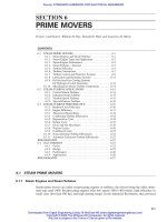
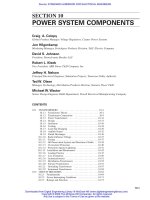
Electromagnetic Induction. A magnetic field is
represented by continuous lines of flux considered to
emerge from a north pole and to enter a south pole.
When the number of such lines linked by a coil is
changed (Fig. 8-3), a voltage is induced in the coil
equal to 1 V for a change of 10
8
linkages/s (Mx/s) for
each turn of the coil, or E ϭ (⌬fT ϫ 10
–8
)/t V.
If the flux lines are deformed by the motion of the
coil conductor before they are broken, the direction
of the induced voltage is considered to be into the
conductor if the arrows for the distorted flux are
shown to be pointing clockwise and outward if coun-
terclockwise. This is generator action (Fig. 8-4).
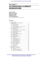
Force on Current-Carrying Conductors in a Magnetic Field. If a conductor carries current, loops
of flux are produced around it (Fig. 8-5). The direction of the flux is clockwise if the current flows
away from the viewer into the conductor, and counterclockwise if the current in the conductor flows
toward the viewer.
FIGURE 8-3 Generated emf by coil movement in
a magnetic field.
FIGURE 8-4 Direction of induced emf by conductor movement in a magnetic field.
Beaty_Sec08.qxd 17/7/06 8:34 PM Page 8-3
Downloaded from Digital Engineering Library @ McGraw-Hill (www.digitalengineeringlibrary.com)
Copyright © 2006 The McGraw-Hill Companies. All rights reserved.
Any use is subject to the Terms of Use as given at the website.
DIRECT-CURRENT GENERATORS
8-4 SECTION EIGHT
FIGURE 8-5 Magnetic fields caused by current-carrying conductors.
FIGURE 8-6 Force on a current-carrying conductor in a magnetic field.
If this conductor is in a magnetic field, the combination of the flux of the field and the flux pro-
duced by the conductor may be considered to cause a flux concentration on the side of the conductor,
where the two fluxes are additive and a diminution on the side where they oppose. A force on the con-
ductor results that tends to move it toward the side with reduced flux (Fig. 8-6). This is motor action.
Generator and Motor Reactions. It is evident that a dc generator will have its useful voltage
induced by the reactions described above, and an external driving means must be supplied to rotate
the armature so that the conductor loops will move through the flux lines from the stationary poles.
However, these conductors must carry current for the generator to be useful, and this will cause
retarding forces on them. The prime mover must overcome these forces.
In the case of the dc motor, the conductor loops will move through the flux, and voltages will be
induced in them. These induced voltages are called the “counter emf,” and they oppose the flow of
currents which produce the forces that rotate the armature. Therefore, this emf must be overcome by
an excess voltage applied to the coils by the external voltage source.
Direct-Current Features. Direct-current machines require many conductors and two or more sta-
tionary flux-producing poles to provide the needed generated voltage or the necessary torque. The
direction of current flow in the armature conductors under each particular pole must always be cor-
rect for the desired results (Fig. 8-7). Therefore, the current in the conductors must reverse at some
time while the conductors pass through the space between adjacent north and south poles.
This is accomplished by carbon brushes connected to the external circuit. The brushes make con-
tact with the conductors by means of the commutator.
To describe commutation, the Gramme-ring armature winding (which is not used in actual
machines) is shown in Fig. 8-8. All the conductors are connected in series and are wound around a
steel ring. The ring provides a path for the flux from the north to the south pole. Note that only the
outer portions of the conductors cut the flux as the ring rotates. Voltages are induced as shown. With
no external circuit, no currents flow, because the voltages induced in the two halves are in opposition.
Beaty_Sec08.qxd 17/7/06 8:34 PM Page 8-4
Downloaded from Digital Engineering Library @ McGraw-Hill (www.digitalengineeringlibrary.com)
Copyright © 2006 The McGraw-Hill Companies. All rights reserved.
Any use is subject to the Terms of Use as given at the website.
DIRECT-CURRENT GENERATORS
DIRECT-CURRENT GENERATORS 8-5
FIGURE 8-7 Direction of
current in generator and motor.
FIGURE 8-8 Principle of commutation.
However, if the coils are connected at a commutator C made up of copper blocks insulated from each
other, brushes BϪ and Bϩ may be used to connect the two halves in parallel with respect to an external
circuit and currents will flow in the proper direction in the conductors beneath the poles.
As the armature rotates, the coil M passes
from one side of the neutral line to the other
and the direction of the current in it is shown
at three successive instants at a, b, and c in
Fig. 8-9. As the armature moves from a to c
and the brush changes contact from segment 2
to segment 1, the current in M is automatically
reversed. For a short period, the brush contacts
both segments and short circuits the coil. It is
important that no voltage be induced in M
during that time, or the resulting circulating
currents could be damaging. This accounts
for the location of the brushes so that M will
be at the neutral flux point between the poles.
Field Excitation. Because current-carrying conductors produce flux that links them as described
above (in paragraphs on force on current-carrying conductors in a magnetic field), flux from the main
poles is obtained by winding conductors around the pole bodies and passing current through them.
This current may be supplied in different ways. When a generator supplies its own exciting current,
it is “self-excited.” When current is supplied from an external source, it is “separately excited.” When
excited by the load current of the machine, it is “series excited.”
8.3 ARMATURE WINDINGS
Terms. The Gramme-ring winding is not used, because half the conductors (those on the inside of
the ring) cut no flux and are wasted. Figures 8-8, 8-10, and 8-11 show such windings only because
they illustrate types of connections so well.
FIGURE 8-9 Methods of excitation.
Beaty_Sec08.qxd 17/7/06 8:34 PM Page 8-5
Downloaded from Digital Engineering Library @ McGraw-Hill (www.digitalengineeringlibrary.com)
Copyright © 2006 The McGraw-Hill Companies. All rights reserved.
Any use is subject to the Terms of Use as given at the website.
DIRECT-CURRENT GENERATORS
8-6 SECTION EIGHT
A singly reentrant winding closes on itself only after including
all the conductors, as shown in Figs. 8-8 and 8-10.
A doubly reentrant winding closes on itself after including half
the conductors, as shown in Fig. 8-11.
As shown, a simplex winding has only two paths through the
armature from each brush (Fig. 8-8). A duplex winding has twice as
many paths from each brush and is shown in Figs. 8-10 and 8-11.
Note that each brush should cover at least two commutator seg-
ments with a duplex winding, or one circuit will be disconnected at
times from the external circuit. Although it is possible to use multi-
plex and multiple reentrant windings, they are uncommon in the
United States. They are used in Europe in some large machines.
Modern dc machines have the armature coils in radial slots in
the rotor. Nonmetallic wedges restrain the coils normally, but some
wedgeless rotors use nonmetallic banding around the core, such as
glass fibers in polyester resin. This permits shallower slots and
helps to reduce commutation sparking. However, the top conductors
are near the pole faces and may have high eddy losses. The coil ends
outside the slots are held down on coil supports by glass polyester
bands for both types.
Multiple, or Lap, Windings. Figure 8-12 shows a lap-winding
coil. The conductors shown on the left side lie in the top side of the
rotor slot. Those on the right side lie in the bottom half of another
slot approximately one pole pitch away. At any instant the sides are under adjacent poles, and volt-
ages induced in the two sides are additive. Other coil sides fill the remaining portions of the slots. The
coil leads are connected to the commutator segments, and this also connects the coils to form the
armature winding. This is shown in Fig. 8-13. The pole faces are slightly shorter than the rotor core.
Almost all medium and large dc machines use simplex lap windings in which the number of par-
allel paths in the armature winding equals the number of main poles. This permits the current per
path to be low enough to allow reasonable-sized conductors in the coils.
Windings. Representations of dc windings are necessarily complicated. Figure 8-14 shows the
lap winding corresponding to the Gramme-ring winding of Fig. 8-8. Unfortunately, the nonproduc-
tive end portions are emphasized in such diagrams, and the long, useful portions of the coils in the
core slots are shown as radial lines. Conductors in the upper layers are shown as full lines, and those
FIGURE 8-12 Coil for one-turn
lap winding.
FIGURE 8-10 Singly reentrant
duplex winding.
FIGURE 8-11 Doubly reentrant
duplex winding.
FIGURE 8-13 Multiple, or lap, winding.
Beaty_Sec08.qxd 17/7/06 8:34 PM Page 8-6
Downloaded from Digital Engineering Library @ McGraw-Hill (www.digitalengineeringlibrary.com)
Copyright © 2006 The McGraw-Hill Companies. All rights reserved.
Any use is subject to the Terms of Use as given at the website.
DIRECT-CURRENT GENERATORS
DIRECT-CURRENT GENERATORS 8-7
in the lower layers as dotted lines. The inside end connections are those connected to the commuta-
tor bars. For convenience, the brushes are shown inside the commutator.
Note that both windings have the same number of useful conductors but that the Gramme-ring
winding requires twice the number of actual conductors and twice the number of commutator bars.
Figure 8-15 shows a 6-pole simplex lap winding. Study of this reveals the six parallel paths
between the positive and negative terminals. The three positive brushes are connected outside the
machine by a copper ring Tϩ and the negative brushes by TϪ.
The two sides of a lap coil may be full pitch (exactly a pole pitch apart), but most machines use
a short pitch (less than a pole pitch apart), with the coil throw one-half slot pitch less than a pole
pitch. This is done to improve commutation.
Equalizers. As shown in Fig. 8-15, the parallel paths of the armature circuit lie under different
poles, and any differences in flux from the poles cause different voltages to be generated in the var-
ious paths. Flux differences can be caused by unequal air gaps, by a different number of turns on the
main-pole field coils, or by different reluctances in the iron circuits.
With different voltages in the paths paralleled by the brushes, currents will flow to equalize the
voltages. These currents must pass through the brushes and may cause sparking, additional losses,
and heating. The variation in pole flux is minimized by careful manufacture but cannot be entirely
avoided.
To reduce such currents to a minimum, copper connections are used to short-circuit points on the
paralleled paths that are supposed to be at the same voltage. Such points would be exactly two pole
pitches apart in a lap winding. Thus in a 6-pole simplex lap winding, each point in the armature cir-
cuit will have two other points that should be at its exact potential. For these points to be accessible,
the number of commutator bars and the number of slots must be a multiple of the number of poles
divided by 2.
These short-circuited rings are called “equalizers.” Alternating currents flow through them
instead of the brushes. The direction of flow is such that the weak poles are magnetized and the
strong poles are weakened. Usually, one coil in about 30% of the slots is equalized. The cross-
sectional area of an equalizer is 20% to 40% that of the armature conductor.
Involute necks, or connections, to each commutator bar from conductors two pole pitches apart
give 100% equalization but are troublesome because of inertia and creepage insulation problems.
Figure 8-15 shows the equalizing connections behind the commutator connections. Normally
they are located at the rear coil extensions, and so they are more accessible and less subject to
carbon-brush dust problems.
Two-Circuit, or Wave, Windings. Figure 8-16 shows a wave type of coil. Figure 8-17 gives a
6-pole wave winding. Study reveals that it has only two parallel paths between the positive and neg-
ative terminals. Thus, only two sets of brushes are needed. Each brush shorts p/2 coils in series.
Because points a, b, and c are at the same potential (and, also, points d, e, and f ), brushes can be
placed at each of these points to allow a commutator one-third as long.
FIGURE 8-14 Simplex lap winding.
FIGURE 8-15 Simplex singly reentrant full-pitch
multiple winding with equalizers.
Beaty_Sec08.qxd 17/7/06 8:34 PM Page 8-7
Downloaded from Digital Engineering Library @ McGraw-Hill (www.digitalengineeringlibrary.com)
Copyright © 2006 The McGraw-Hill Companies. All rights reserved.
Any use is subject to the Terms of Use as given at the website.
DIRECT-CURRENT GENERATORS
8-8 SECTION EIGHT
FIGURE 8-16 One-turn wave winding.
The winding must progress or retrogress by one commutator bar each time it passes around the
armature for it to be singly reentrant. Thus, the number of bars must equal (kp/2) Ϯ 1, where k is a
whole number and p is the number of poles. The winding needs no equalizers because all conduc-
tors pass under all poles.
Although most wave windings are 2-circuit, they can be multicircuit, as 4 or 16 circuits on a
4-pole machine or 6, 12, or 24 circuits on a 12-pole machine. Multicircuit wave windings with the same
number of circuits as poles can be made by using the same slot and bar combinations as on a lap wind-
ing. For example, with an 8-pole machine with 100 slots and 200 commutator bars, the bar throw for a
simplex lap winding would be from bar 1 to bar 2 and then from bar 2 to bar 3, etc. For an 8-circuit
wave winding, the winding must fail to close by circuits/2 bars, or 4. Thus, the throw would be bar 1 to 50,
to bar 99, to bar 148, etc. The throw is (bars Ϯ circuits/2)(p/2), in this case, (200 Ϫ 4)/4 ϭ 49.
Theoretically such windings require no equalizers, but better results are obtained if they are used.
Since both lap and multiple wave windings can be wound in the same slot and bar combination
simultaneously, this is done by making each winding of half-size conductors. This combination resem-
bles a frog’s leg and is called by that name. It needs no equalizers but requires more insulation space
in the slots and is seldom used.
Some wave windings require dead coils. For instance, a large 10-pole machine may have a circle
of rotor punchings made of five segments to avoid variation in reluctance as the rotor passes under
the five pairs of poles. To avoid dissimilar slot arrangements in the segments, the total number of
slots must be divisible by the number of segments, or 5 in this case. This requires the number of com-
mutator bars to be also a multiple k of 5. However, the bar throw for a simplex wave winding must
be an integer and equal to (bars Ϯ 1)(p/2). Obviously (5k Ϯ 1)/5 cannot meet this requirement.
Consequently one coil, called a dead coil, will not be connected into the winding, and its ends will
be taped up to insulate it completely. No bar will be provided for it, and thus the bar throw will be
an integer. Dead coils should be avoided because they impair commutation.
8.4 ARMATURE REACTIONS
Cross-Magnetizing Effect. Figure 8-18a represents the magnetic field produced in the air gap of a
2-pole machine by the mmf of the main exciting coils, and part b represents the magnetic field pro-
duced by the mmf of the armature winding alone when it carries a load current. If each of the Z arma-
ture conductors carries I
c
A, then the mmf between a and b is equal to ZI
c
/p At. That between c and d
(across the pole tips) is cZI
c
/p At, where c ϭ ratio of pole arc to pole pitch. On the assumption that
all the reluctance is in the air gap, half the mmf acts at ce and half at fd, and so the cross-magnetizing
effect at each pole tip is
FIGURE 8-17 Two-circuit progressive
winding.
Beaty_Sec08.qxd 17/7/06 8:34 PM Page 8-8
Downloaded from Digital Engineering Library @ McGraw-Hill (www.digitalengineeringlibrary.com)
Copyright © 2006 The McGraw-Hill Companies. All rights reserved.
Any use is subject to the Terms of Use as given at the website.
DIRECT-CURRENT GENERATORS
DIRECT-CURRENT GENERATORS 8-9
ampere-turns (8-1)
for any number of poles.
Field Distortion. Figure 8-18c shows the resultant magnetic field when both armature and main
exciting mmfs exist together; the flux density is increased at pole tips d and g and is decreased at tips
c and h.
Flux Reduction Due to Cross-Magnetization. Figure 8-19 shows part of a large machine with
p poles. Curve D shows the flux distribution in the air gap due to the main exciting mmf acting alone,
with flux density plotted vertically. Curve G shows the distribution of the armature mmf, and curve
F shows the resultant flux distribution with both acting. Since the armature teeth are saturated at nor-
mal flux densities, the increase in density at f is less than the decrease at e, so that the total flux per
pole is diminished by the cross-magnetizing effect of the armature.
Demagnetizing Effect of Brush Shift. Figure 8-20 shows the magnetic field produced by the arma-
ture mmf with the brushes shifted through an angle u to improve commutation. The armature field is
no longer at right angles to the main field but may be considered the resultant of two components,
one in the direction OY, called the “cross-magnetizing component,” and the other in the direction OX,
which is called the “demagnetizing component” because it directly opposes the main field. Figure 8-21
gives the armature divided to show the two components, and it is seen that the demagnetizing
ampere-turns per pair of poles are
ampere-turns (8-2)
ZI
c
p
ϫ
2u
180
cZI
c
2p
FIGURE 8-18 Flux distribution in (a) main field,
(b) armature field, and (c) load conditions.
FIGURE 8-19 Flux distribution in
a large machine with p poles.
FIGURE 8-21 Cross-magnetizing effect.
FIGURE 8-20 Demagnetizing effect.
Beaty_Sec08.qxd 17/7/06 8:34 PM Page 8-9
Downloaded from Digital Engineering Library @ McGraw-Hill (www.digitalengineeringlibrary.com)
Copyright © 2006 The McGraw-Hill Companies. All rights reserved.
Any use is subject to the Terms of Use as given at the website.
DIRECT-CURRENT GENERATORS
8-10 SECTION EIGHT
where 2u/180 is about 0.2 for small noncommutating
pole machines where brush shift is used. The demag-
netizing ampere-turns per pole would be
0.1ZI
c
/p ampere-turns (8-3)
No-Load and Full-Load Saturation Curves. Curve 1
of Fig. 8-22 is the no-load saturation curve of a dc gen-
erator. When full-load current is applied, there is a
decrease in useful flux, and therefore a drop in voltage
ab due to the armature cross-magnetizing effect (see
paragraph on flux reduction, above). A further volt-
age drop from brush shift is counterbalanced by an
increase in excitation bc ϭ 0.1 ZIc/p; also a portion cd
of the generated emf is required in overcoming the volt-
age drop from the current in the internal resistance of
the machine. The no-load voltage of 240 V requires
8000 At. At full load at that excitation the terminal voltage
drops to 220 V. To have both no-load and full-load
voltages equal to 240 V, a series field of 10,700 Ϫ 8000 ϭ
2700 At would be required.
8.5 COMMUTATION
Commutation Defined. The voltages generated in all conductors under a north pole of a dc genera-
tor are in the same direction, and those generated in the conductors under a south pole are all in the
opposite direction (Fig. 8-23). Currents will flow in the same direction as induced voltages in gen-
erators and in the opposite direction in motors. Thus, as a conductor of the armature passes under a
brush, its current must reverse from a given value in one direction to the same value in the opposite
direction. This is called “commutation.”
Conductor Current Reversal. If commutation is “perfect,” the change of the current in a coil will be
linear, as shown by the solid line in Fig. 8-24. Unfortunately, the conductors lie in steel slots, and
self-and mutual inductances in Fig. 8-25 cause voltages in the coils short-circuited by the brushes.
These result in circulating currents that tend to prevent the initial current change, delaying the rever-
sal. In extreme cases, the delay may be as severe as indicated by the dotted line of Fig. 8-24. Because
the current must be reversed by the time the coil leaves the brush (when there is no longer any path
for circulating currents), the current remaining to be reversed at F must discharge its energy in an
FIGURE 8-22 Saturation curves—dc generator.
FIGURE 8-23 Conductor currents.
Beaty_Sec08.qxd 17/7/06 8:34 PM Page 8-10
Downloaded from Digital Engineering Library @ McGraw-Hill (www.digitalengineeringlibrary.com)
Copyright © 2006 The McGraw-Hill Companies. All rights reserved.
Any use is subject to the Terms of Use as given at the website.
DIRECT-CURRENT GENERATORS
DIRECT-CURRENT GENERATORS 8-11
electric arc from the commutator bar to the heel of the
brush. This is commutation sparking. It can burn the
edges of the commutator bars and the brushes.
However, most large and heavy-duty dc machines have
some nondamaging sparking, and “sparkless” commuta-
tion is not required by accepted standards. However,
commutation must not require undue maintenance.
The undesired voltages causing the circulating cur-
rents result from interpolar fluxes from armature reac-
tion, leakage fluxes of the current-carrying armature
conductors, and, in some cases, main-pole-tip spray flux.
Beneficial factors reducing the circulating currents
include the resistance of the short-circuited coil, the
resistance of the commutator risers, and that of the brush body to transverse currents. However,
the most important factor is the voltage drop at the sliding contact between the brush face and the
copper commutator surface.
Commutator Brushes. Most dc machines use electrographitic brushes with about 60 A/in
2
current
density at full load. These have an essentially constant contact voltage drop at the commutator surface
of about 1 V for loads above one-third. This effective resistance to circulating currents is important to
good operation of dc machines.
The cross-resistance of the brush body to circulating currents can be increased by splitting the
brush into two wafers and making the crosscurrents cross the air gap between the two pieces. This
has increased the good commutation range on some machines by 7%. The use of double brush hold-
ers, which have metal dividers between two brushes in the holder, is even more effective and has
increased the good commutation range as much as 15% over single solid brushes.
Unless special brushes are used, machines should be operated for not more than a few hours at a
time at brush densities below 30 A/in
2
. If this is done, the commutator surface develops a hard glaze
which makes the brushes chatter. This results in frayed shunts, chipped and broken brushes, and
excessive brush-finger wear.
Reactance Voltage of Commutation. The sum of the voltages induced in the armature coil while it is
short-circuited by the brushes while undergoing commutation is called the reactance voltage of com-
mutation. One of the most important of the fluxes causing this voltage is the slot-leakage flux shown in
FIGURE 8-24 Commutation.
FIGURE 8-25 Magnetic field surrounding
short-circuited coils.
Beaty_Sec08.qxd 17/7/06 8:34 PM Page 8-11
Downloaded from Digital Engineering Library @ McGraw-Hill (www.digitalengineeringlibrary.com)
Copyright © 2006 The McGraw-Hill Companies. All rights reserved.
Any use is subject to the Terms of Use as given at the website.
DIRECT-CURRENT GENERATORS
8-12 SECTION EIGHT
Fig. 8-26. This is the resultant flux leakage from current in the individual slot conductors, as shown in
Fig. 8-25. Because the radial fluxes in the rotor teeth from adjacent slot conductors essentially cancel
except at point C (the point of current reversal), the resultant flux is as shown in Fig. 8-26. As the con-
ductors commutate and pass through C, they cut the flux shown there and this generates the reactance
voltage of commutation. Actually, part of this voltage is also due to leakage-flux changes at the coil
ends, to armature reaction flux, etc., but, for simplicity, only the important slot leakage flux is shown.
Commutating Poles. The beneficial factors that limit the circulating currents in coils being com-
mutated are not adequate to prevent serious delays in current reversal. Other means must be taken to
prevent sparking.
If the flux at C (Fig. 8-26) could be nullified by an equal flux in the opposite direction, the cir-
culating currents due to the slot leakage flux would be prevented.
The location of C is fixed by the location of the brushes. If the brushes were shifted toward the
south main pole, a position could be found where the main flux upward into the south pole would
cancel the downward flux due to slot leakage at C.
This method was used in the early history of dc machines. Unfortunately, the slot-leakage flux at
C is proportional to conductor load current, whereas the flux into the south pole is not. Thus, a new
brush position is needed for every change in load current.
A better solution is to provide stationary poles midway between the main poles, as shown in
Fig. 8-27. Windings on these commutating poles carry the load current. Thus, the flux into the pole
at C is proportional to the rotor conductor currents and, theoretically, can cancel the voltages induced
in the coils being commutated by the slot leakage flux. In the case of the dc motor, the current
FIGURE 8-26 Slot-leakage flux.
FIGURE 8-27 Slot-leakage flux and commutating-pole flux.
Beaty_Sec08.qxd 17/7/06 8:34 PM Page 8-12
Downloaded from Digital Engineering Library @ McGraw-Hill (www.digitalengineeringlibrary.com)
Copyright © 2006 The McGraw-Hill Companies. All rights reserved.
Any use is subject to the Terms of Use as given at the website.
DIRECT-CURRENT GENERATORS
DIRECT-CURRENT GENERATORS 8-13
reverses in both the armature and the commutating field, and
proper canceling is maintained.
Note that the strength of the commutating-pole winding must
be greater than the armature-winding ampere-turns per pole by the
amount required to carry the needed flux across the commutating-
pole air gap.
Almost all modern dc machines use commutating poles, although
some small machines have only half as many as main poles.
The commutating-pole tip is usually shaped with tapered sides
to approximate the shape of the reactance voltage of commutation
form (see Figs. 8-27 and 8-28).
Reactance Voltage of Commutation Formula. To determine the
useful flux needed across the commutating-pole air gap, it is use-
ful to calculate the reactance voltage of commutation (the total of
the voltages induced in the armature coil as it undergoes commu-
tation). The approximate value of this voltage may be calculated
by the use of the following formula:
(8-4)
where I
c
ϭ current per armature conductor, A
Z ϭ total no. of armature conductors
T ϭ no. of turns/coil between commutator bars
L
r
ϭ gross armature-core length, in
K
1
ϭ 18.5 for noncommutating-pole machines
ϭ 0 for machines with commutating-pole length ϭ L
r
K
2
ϭ 1.0 for machines using nonmagnetic bands
ϭ 1.7 for machines using magnetic bands
PP ϭ pole pitch, in
t
s
ϭ coil throw, slots
b
s
ϭ width of slot, in
d
s
ϭ depth of slot, in
SP ϭ slot pitch, in
This formula is based on the work by Lamme. (See Theory of Commutation by B. G. Lamme, Trans.
AIEE, Oct. 1911, vol. 30.)
The Commutating Zone. This is defined as that space on the armature periphery through which a
given slot moves while all the conductors lying in the slot commutate. In chorded windings, it is
extended to include the coil edges in the chorded slots. The commutating zone thus depends on the
number of commutating bars covered per brush.
The zone may be calculated by the following formula:
(8-5)
where CZ is the commutating zone in inches, SP the rotor slot pitch in inches, B/S the number of
commutator bars per slot, Ch the slot chording as a fraction of the slot pitch, B/Br the number of
commutator bars spanned per brush, Cir the number of paralleled circuits in the armature, and p the
number of main poles.
Consider an 8-pole simplex lap winding with three bars per slot, chording of
1
/
2
slot, 3
1
/
2
bars per
brush, and slot pitch of 1.05 in:
CZ ϭ
1.05 ϫ (3 ϩ 1
1
/
2
ϩ 3
1
/
2
Ϫ 8/8
3
ϭ 2.44 in
CZ ϭ
SP[(B/S) ϩ (B/S ϫ Ch) ϩ (B/Br) Ϫ Cir/p)]
B/S
E
c
ϭ
poles
paths
(l
c
ZT)(r/min)(10
Ϫ10
) c(K
i
L
r
) ϩ K
2
(PP)(4.5 ϩ 0.2t
s
) ϩ
L
r
b
s
(3d
s
ϩ 2SP)d volts
FIGURE 8-28 Commutating zone.
Beaty_Sec08.qxd 17/7/06 8:34 PM Page 8-13
Downloaded from Digital Engineering Library @ McGraw-Hill (www.digitalengineeringlibrary.com)
Copyright © 2006 The McGraw-Hill Companies. All rights reserved.
Any use is subject to the Terms of Use as given at the website.
DIRECT-CURRENT GENERATORS
8-14 SECTION EIGHT
In this machine, all the conductors in a slot are commutated while the armature periphery
moves 2.44 in.
This can be seen graphically in Fig. 8-28, where (a) shows a slot with six conductors, (b) shows
a brush covering 3
1
/
2
bars, and (c) shows the graphical solution. In (c) the rectangle a represents as
abscissa the space of 3
1
/
2
commutator bars if they were at the armature surface. This is the length to
commutate coil a. The ordinate represents to a convenient scale the commutation voltage induced in
this conductor while it is being commutated. Rectangles b and c are the same for coils b and c. Since
b commutates 1 bar later than a, it is shown one bar space to the right of a, etc. In a similar manner
d, e, and f are shown. Normally d would be expected to start commutation at the same time as a, but,
because of chording, it starts later, in this case 1
1
/
2
bars later. Thus, the commutating zone starts with
the beginning of rectangle a and is completed at the end of rectangle f. On adding the spaces of the
parts, this is 3
1
/
2
bars for f, 2 bars for the steps of e and d, and 1
1
/
2
bars for chording, or a total of
7 bars at the rotor surface, which is 1.05
7
/
3
, or 2.44 in.
The summation of the individual rectangles as smoothed off by curve A of (c) is a rough repre-
sentation of the reactance voltages induced in the coils during commutation.
Single Clearance. The centerline of the commutating zone and curve A of Fig. 8-28 lie midway
between the adjacent main-pole tips if the brushes are not shifted off neutral. The arc on the rotor sur-
face between the tips of adjacent main poles is called the neutral zone. If the commutating zone is cen-
tered in this arc, the spaces left at each end are called the single clearance. Thus, the single clearance is
(8-6)
The single clearance is an indication of the probability that spray flux from the main-pole tips
might flow into the commutating zone. Such flux would not vary with load and would distort the
form of the useful flux from the commutating pole. The commutating-pole useful flux form should
closely resemble that of curve A in Fig. 8-28.
Noncompensated dc machines usually have main-pole tips with short radial dimensions and have
limited spray flux into the neutral zone. The minimum single clearance for these should be not less
than 0.6 in and not less than 0.9 in with commutation voltages above 3 or 4 V.
Compensated-machine main poles usually have tips 2 to 3 in deep to accommodate the compen-
sating slots and are more likely to spray flux into the commutating zone. These require single-clearance
minimums of 1.2 to 1.4 in.
If there is any question about tip flux reaching the commutating zone, flux plots should be made.
Commutating-Pole Excitation. Figures 8-18b and 8-19 show that flux should normally be expected
in the commutation area. It is caused by the armature-winding ampere-turns per pole. It could be
reduced to zero if the commutating pole had ampere-turns equal and opposite to those of the arma-
ture winding. This is ZI
c
/2p At/pole.
However, it is necessary that the commutating winding also produces useful flux across the
commutating-pole gap to counteract the reactance voltage of commutation, as shown in Fig. 8-27.
For this reason, the strength of the commutating field is usually 20% to 30% greater than the arma-
ture ampere-turns per pole. This difference is called the excess ampere-turns. These must be added
to the circled dotted-line bar diagram of Fig. 8-29. The actual flux across the gap is set accurately
during the factory test by adjusting the number of sheet-steel shims behind the commutating poles
to set the reluctance of the gap for the exact flux needed.
Calculation of Commutating-Pole Air Gaps. With fixed excess ampere-turns on the commutating-
pole winding and a certain commutation voltage at rated current and speed, only one particular
commutating-pole air gap will result in the most favorable compensation of the commutation voltage.
The shape of the pole tip will determine the form of the flux density under it, but the length of the
air gap will determine the magnitude of the density.
To counteract the reactance voltage of commutation E
c
, the approximate maximum flux density
needed in the commutating-pole air gap is
SC ϭ (neutral zone Ϫ commutating zone)/2
Beaty_Sec08.qxd 17/7/06 8:34 PM Page 8-14
Downloaded from Digital Engineering Library @ McGraw-Hill (www.digitalengineeringlibrary.com)
Copyright © 2006 The McGraw-Hill Companies. All rights reserved.
Any use is subject to the Terms of Use as given at the website.
DIRECT-CURRENT GENERATORS
DIRECT-CURRENT GENERATORS 8-15
FIGURE 8-29 Commutating-pole ampere-turns.
(8-7)
where E
c
is the full-load reactance voltage of commutation at speed r/min, Z is the total number of
armature conductors, bars is the total number of commutator bars, D is the armature diameter in
inches, L
c
is the axial length of the commutating poles in inches, and r/min is the revolutions per
minute for which E
c
was calculated.
The approximate length of the needed commutating-pole single air gap may be calculated by the
following formula:
(8-8)
When the machine is on factory test, the excess ampere-turns can be adjusted to obtain the best
commutation possible by placing another dc generator or a battery across the commutating winding
to add to the load current flowing in it or to lower the excess by shunting out some of the load cur-
rent. This is known as a “boost or buck” test. Afterward the commutating-pole air gap is changed to
produce the “best” gap flux density with the actual excess ampere-turns. The new gap will be
(8-9)
Dimensions of Commutating Poles. If the useful flux across a commutating-pole air gap is not
proportional to the machine load current, the compensation of the reactance voltage of commutation
will not be correct for all loads and sparking may damage the brushes and commutator. Thus, the
commutating pole must not saturate at the highest load currents to be accommodated. The base of
the pole must carry not only the useful air-gap flux but also leakage fluxes from the commutating and
main field coils which are near. These leakage fluxes are relatively large and must be determined with
care by flux plotting if the danger of commutating-pole saturation exists.
Gap
2
ϭ
excess At
1
excess At
2
ϫ gap
1
Gap ϭ
3.19 ϫ excess ampere-turns
B
m
B
m
ϭ
E
c
ϫ 23 ϫ 10
8
Z / bar ϫ DL
c
ϫ r/min
Beaty_Sec08.qxd 17/7/06 8:34 PM Page 8-15
Downloaded from Digital Engineering Library @ McGraw-Hill (www.digitalengineeringlibrary.com)
Copyright © 2006 The McGraw-Hill Companies. All rights reserved.
Any use is subject to the Terms of Use as given at the website.
DIRECT-CURRENT GENERATORS
8-16 SECTION EIGHT
FIGURE 8-30 Armature field without (a) and with
(b) compensating windings.
The amount of leakage flux through the base of the pole depends on the length of the leakage
paths, the number of coil ampere-turns, and the location of the commutating field. The leakage paths
should be made as long as feasible, the coil ampere-turns as few as reasonable, and the commutat-
ing coil located as close to the pole tip as possible. Also, all sections of the commutating pole should
be large enough to accommodate their flux.
For a normal compensated machine, the leakage flux will be about 75% of the commutating-pole
useful flux, or about 140% of the useful flux in a noncompensated machine.
The approximate useful flux can be calculated by using the maximum commutating-pole air-gap
flux density from Eq. (8-7). The average flux density of the commutating zone will be approximately
(8-10)
The flux density at overload in the base of the pole is
(8-11)
where K
3
is 1.75 for compensated machines and 2.40 for noncompensated machines, K
4
is the ratio
of overload current to rated current, B
a
is the average flux density in the commutating zone, CZ is
the width of the commutating zone, L
c
is the axial length of the commutating pole, and W
c
is the cir-
cumferential width of the pole at its base. B
cp
should not exceed 80,000 to 90,000 lines/in
2
for good
commutation.
Compensating Windings. Although the commutating pole is a good solution for commutation, it
does not prevent distortion of the main-pole flux by armature reaction. The flux set up across the
main-pole face by the armature mmf is shown in Fig. 8-30a. If the pole face is provided with another
winding, as shown in Fig. 8-30b, and connected in series with the load, it can set up an mmf equal
and opposite to that of the armature. This would tend to prevent distortion of the air-gap field by
armature reaction. Such windings are called compensating windings and are usually provided on
medium-sized and large dc machines to obtain the best possible characteristics. They are also often
needed to make machines less susceptible to flashovers.
The use of compensating windings reduces the number of turns required on the commutating-
pole fields, and this materially reduces the leakage fluxes of the field and, in turn, the pole satura-
tions at high currents. The ampere-turns on the commutating field are reduced by about 50% with
the use of a compensating field. This new winding may be considered to be some of the turns taken
off the commutating-pole winding and relocated in slots in the main-pole faces.
The number and location of the compensating slots must be carefully chosen to match, as closely
as possible, the rotor ampere-turns per inch. However, the slot spacing must not correspond closely to
that of the rotor. This would cause a major change in reluctance to the main-pole useful flux every time
the rotor moved from a position where the rotor and stator slots all coincided to where the rotor slots
coincided with the stator teeth. This would occur once for every slot-pitch movement. The resulting
rapid changes in useful flux would cause ripples in the output voltage and also serious magnetic noise.
If too few slots are used, local flux distortions occur and the compensating winding loses some of its
effectiveness (see Fig. 8-32).
B
cp
ϭ
K
3
ϫ K
4
ϫ B
a
ϫ CZ
L
c
ϫ W
c
B
a
ϭ 0.83B
m
Beaty_Sec08.qxd 17/7/06 8:34 PM Page 8-16
Downloaded from Digital Engineering Library @ McGraw-Hill (www.digitalengineeringlibrary.com)
Copyright © 2006 The McGraw-Hill Companies. All rights reserved.
Any use is subject to the Terms of Use as given at the website.
DIRECT-CURRENT GENERATORS
DIRECT-CURRENT GENERATORS 8-17
Compensation of armature reaction effectively
reduces the armature circuit inductance. This makes the
machine less susceptible to the bad effects of L(di/dt)
voltages caused by very fast load current changes.
During manufacture, it is possible to locate the com-
pensating winding nonsymmetrically about the center-
line of the main pole. This causes a direct-axis flux,
which will give a series field effect (Fig. 8-31). For gen-
erator cumulative compounding, the slots must be shifted
in the direction of the machine rotation. This shift gives
a motor differential compounding. The effect cannot be
adjusted after manufacture. It seldom exceeds
1
/
2
in, and
this does not materially reduce the effectiveness of the
compensation.
Volts per Bar. The mica thickness between the commutator segments depends on the machine
design and varies from 0.020 in on small machines to 0.050 in on large units. Although several hun-
dred volts would normally be required to jump these distances, the presence of ionized air from
sparking and the presence of conducting carbon dust make it necessary that the voltage between
segments be held to low values. If a low-resistance arc does jump between segments, it raises the
voltages across the remaining bars. It also tends to ionize some air to form conducting paths across
the rest of the bars. If this progresses until all the segments between brush arms of opposite polar-
ity are bridged, then a flashover occurs and severe damage may result to the commutator, brushes,
and brush holders.
Because the highest voltage between bars is the “trigger” that starts the flash, this is an important
limit. The “average” volts per bar has little significance. Figure 8-29 shows that the maximum volts
per bar depends on the field form. For the noncompensated machine shown, the maximum volts
between segments exists at w. The segments connected to conductors at x have much less voltage
between them, and those beyond the edge of the pole have almost none.
The relation between maximum volts per bar and the average depends on the armature ampere-
turns per pole and the saturation curve of the gap and teeth at the pole tips. On neglecting the small
voltage drop in the series and commutating windings, the voltage between brush arms is the machine
voltage V, and the number of bars between arms is B/p. Thus
(8-12)
where B is the total number of commutator bars and p the number of main poles.
Even if no distortion exists, only the conductors under the pole faces generate voltage, and so the
corrected average volts per bar should be
where c is the ratio of pole arc to pole pitch, about 0.65. This is represented by D in Fig. 8-29.
However, the maximum volts per bar at w is greater than this, as the height w is greater than D, or
(8-13)
In practice, the value of w/D for a noncompensated machine at full-strength main field varies
from about 1.7 to 1.9. However, any reduction in saturation causes the effects of the armature
ampereturns (which cause the distortion) to be magnified. The designer must check the actual
value of w/D, since it may be as high as 4.5 for a dc motor at a weak main field strength (high
speed). This is evident in Fig. 8-32. The distorting effect for the high-speed (low-average-flux)
condition f
02
raises the maximum flux to f
w2
, which is over 3 times the change for the saturated
Maximum volts per bar ϭ
V ϫ p
B
ϫ
w
D ϫ c
V ϫ p
B ϫ c
volts
Average volts/bar ϭ
V ϫ p
B
FIGURE 8-31 Offset compensating winding.
Beaty_Sec08.qxd 17/7/06 8:34 PM Page 8-17
Downloaded from Digital Engineering Library @ McGraw-Hill (www.digitalengineeringlibrary.com)
Copyright © 2006 The McGraw-Hill Companies. All rights reserved.
Any use is subject to the Terms of Use as given at the website.
DIRECT-CURRENT GENERATORS
8-18 SECTION EIGHT
FIGURE 8-33 Main-pole flux distortion on a
compensated motor at full load and 2
1
/
2
times
base speed.
(low-speed) condition f
01
to f
w1
with the same dis-
torting ampere-turns X.
The use of a compensating winding tends to elim-
inate the flux distortion, and for saturated conditions
the flux curve coincides well with the no-load curve
D of Fig. 8-29. However, under low saturation condi-
tions the stationary compensating windings permit
localized flux distortions. These are shown in Fig. 8-33.
Similar distortions occur at low main flux densities
on dc generators, but the output voltage V is reduced
in the same proportion as the main flux, and the
maximum voltage between bars is not affected
seriously.
At full field on well-compensated motors or genera-
tors w/D is about 1.4 to 1.5. Direct-current motors at
weak field may have ratios of 2.0 or more. On any ques-
tionable machine the designer should check this value
carefully.
Approximate safe limits of maximum volts per bar
are 40 V for motors and 30 V for generators on
machines having 0.040-in-thick mica between
segments.
Brush Potential Curves. When a dc machine devel-
ops some commutation sparking, the user may suspect
that the commutating-pole air gap is not set correctly. “Brush potential curves” are often taken to
prove or disprove such suspicions.
These are taken by measuring the voltage drops between the brush and commutator surface at
four points while the machine is operating at constant speed and load current (see Fig. 8-34). The
voltages at 1, 2, 3, and 4 are taken by touching the pointed lead of a wooden pencil to the commu-
tator surface. The circuit is completed with leads and a low-reading voltmeter is shown.
The voltages are then plotted. A curve such as A of Fig. 8-34 may indicate undercompensation
due to a too large commutating-pole gap. Curve C may indicate overcompensation with too much
flux density in the commutating-pole air gap. Curve B is typical of good compensation.
Justification for such conclusions is based on the theory that best commutation (coil current rever-
sal) will be linear while the coil passes under the brush. This is possible only if there are no circu-
lating currents. Undercompensation should cause circulating currents that would crowd the current
to the leaving edge of the brush and cause a high voltage at point 4. Overcompensation would reverse
the current too soon and would actually reverse the voltage drop at point 4.
FIGURE 8-34 Brush potential curves.
FIGURE 8-32 Effect of flux-distortion armature
ampere-turns at normal and low saturation.
Beaty_Sec08.qxd 17/7/06 8:34 PM Page 8-18
Downloaded from Digital Engineering Library @ McGraw-Hill (www.digitalengineeringlibrary.com)
Copyright © 2006 The McGraw-Hill Companies. All rights reserved.
Any use is subject to the Terms of Use as given at the website.
DIRECT-CURRENT GENERATORS
DIRECT-CURRENT GENERATORS 8-19
Even to an expert, this test is only an indicator that more definitive tests, such as a buck-boost test,
are needed [see Eq. (8-8)]. Many other factors, including brush riding, commutator surface conditions,
and sparking, influence the readings. Where machine changes may be required, the manufacturer
should be consulted.
8.6 ARMATURE DESIGN
EMF Equation. If 10
8
lines (Mx) of flux are cut by one conductor in 1 s, 1 V is induced in it.
Therefore, the induced voltage of a dc machine is
(8-14)
where f
t
is the total flux in maxwells across the main air gaps and Z/C is the number of conductors
in series per circuit (C).
Output Equation. Equation (8-14) is converted to watts output if both sides are multiplied by the
load current I
L
, I
c
ϫ C. The formula can then be rearranged as
(8-15)
where D is the armature diameter and L is the arma-
ture gross core length, B
g
is the main-pole
air-gap density in maxwells (lines), c is the ratio of
pole arc to pole pitch, q is ZI
c
/pD (a useful loading
factor), and f
t
is the total air-gap flux equal to
B
g
cpDL (8-16)
Rotor Speeds. Standards list dc generator speeds as
high as are reasonable to reduce their size and cost.
This relation is seen from Eq. (8-15). The speeds may
be limited by commutation, maximum volts per bar,
or the peripheral speeds of the rotor or commutator.
Generator commutators seldom exceed 5000 ft/min,
although motor commutators may exceed 7500 ft/min
at high speeds. Generator rotors seldom exceed 9500
ft/min. Figure 8-35 shows typical standard speeds. If
the prime mover requires lower speeds than these,
generators can be designed for them but larger
machines result.
Rotor Diameters. Difficult commutating generators
benefit from the use of large rotor diameters, but
diameters are limited by the same factors as rotor
speeds listed above. The resultant armature length
should be not less than 60% of the pole pitch, because
such a small portion of the armature coil would be
used to generate voltage. Typical generator diameters
are shown in Fig. 8-36.
D
2
L ϭ
watts ϫ 6.08 ϫ 10
8
r/min ϫ B
g
ϫ c ϫ q
E ϭ f
t
ϫ
Z
C
ϫ
r/min
60
ϫ 10
Ϫ8
FIGURE 8-35 Standard speeds of dc generators.
FIGURE 8-36 Approximate rotor diameters for
standard speeds of dc generator.
Beaty_Sec08.qxd 17/7/06 8:34 PM Page 8-19
Downloaded from Digital Engineering Library @ McGraw-Hill (www.digitalengineeringlibrary.com)
Copyright © 2006 The McGraw-Hill Companies. All rights reserved.
Any use is subject to the Terms of Use as given at the website.
DIRECT-CURRENT GENERATORS
8-20 SECTION EIGHT
Direct-current motor speeds must suit the applica-
tion, and often the rotor diameter is selected to meet the
inertia requirements of the application. Core lengths
may be as long as the diameter. Such motors are usually
force-ventilated.
Number of Poles and Other Rotor Design Factors.
The rotor diameter usually fixes the number of main
poles. Typical pole pitches range from 17.5 to 20.5 in
on medium and large machines. When a choice is
possible, high-voltage generators use fewer poles to
allow more voltage space on the commutator between
the brush arms. However, high-current generators need many poles to permit more current-
carrying brush arms and shorter commutators. Commutators for 1000 to 1250 A/(brush arm)
(polarity) are costly, and lower values should be used where existing dies will permit.
The main-pole air-gap flux density Bg is limited by the density at the bottom of the rotor teeth.
The reduced taper in the teeth of large rotors permits the higher gap densities, as shown in Fig. 8-37.
Ampere conductors per inch of rotor circumference (q) is limited by rotor heating, commutation, and,
at times, saturation of commutating poles. Approximate acceptable values of q are shown in Fig. 8-38.
The commutator diameter is usually about 55% to 85% of the rotor diameter, depending on the
sizes available to the designer, the peripheral speed, and the resulting single clearances. Heating may
also limit the choice.
Brushes and brush holders are chosen from designs available to limit the brush current density to
60 to 70 A/in
2
at full load, to obtain the needed single clearance, and to obtain acceptable commutator
heating.
Selection of an Approximate Design. Consider a generator rated 2500 kW, 700 V, 3571 A, and
514 r/min. From Figs. 8-38 and 8-39
Examination of the data indicates that the design appears feasible, and so we may continue.
Approx. dia. D ϭ 62 in
Available dia. D ϭ 56 in
No. of poles 10
Pole pitch 17.59 in
Pole arc 12.0 in
(Arc/pitch) 0.687
Neutral zone 6.04 in
B
g
gap density at 721 V 58,500 lines/in
2
Approx. q (Fig. 8-38) 1480 A cond./in
D
2
L [Eq. (8-15)] 50,200 in
3
L (gross core) 16 in
No. of
3
/
8
-in vents in core 5
Net core length 14.125 in
f [Eq. (8-14)] 1.12 ϫ 10
8
Approx. total cond. Z 752 (use 750)
Actual q 1520 A cond./in
No. of commutating bars (1-turn lap) 375
No. of slots 125
Slot pitch 1.407 in
Slot throw 12
1
/
2
(use 12)
Chording
1
/
2
-slot pitches
FIGURE 8-37 Curve of apparent gap density
versus armature diameter.
Beaty_Sec08.qxd 17/7/06 8:34 PM Page 8-20
Downloaded from Digital Engineering Library @ McGraw-Hill (www.digitalengineeringlibrary.com)
Copyright © 2006 The McGraw-Hill Companies. All rights reserved.
Any use is subject to the Terms of Use as given at the website.
DIRECT-CURRENT GENERATORS
DIRECT-CURRENT GENERATORS 8-21
Examination of these data also indicates that the proposed design is reasonable.
Armature Slots and Coils. The depth of an armature slot is limited by several factors, including the
tooth density, eddy losses in the armature conductors, available core depths, and commutation. For
reasonable frequencies (up to 50 Hz on medium and large dc machines), slots about 2 in deep can
ordinarily be used.
Acceptable slot pitches range from 0.75 to 1.5 in. Small machines have shallower slots and a
lower range of slot pitches. For medium and large machines, a reasonable tooth density usually
results if the ratio of slot width to slot pitch is about 0.4.
Eddy losses in the conductors can be large compared with their load I
2
R losses. Sometimes these
must be reduced by making each armature conductor from several strands of insulated copper wire.
The number of strands and their size depend on the frequency and the total depth of the conductor.
An approximate formula for reasonable eddy losses is
(8-17)
where f is the frequency in hertz, (r/min ϫ poles)/120, and d
c
is the total depth of a conductor.
No. of strands ϭ (0.168) (f
0.83
)(d
0.4
c
)
Commutating dia. 39 in
Brush size (35°) 2(0.500 ϫ 1.75) in
CZ (commutating zone) [Eq. (8-5)] 3.53 in
Brushes/arm 7b/a
Commutating speed 5250 ft/min
Commutating bar pitch 0.327
Brush arc 1.315 in
Bars/arc 4.02 bars
SC [Eq. (8-6)] 1.26 in
Brush density 58.3 A/in
2
Brush I
2
R [Eq. (8-29)] 7142 W
Length of commutating face 7(1.75 ϩ 0.063) ϩ 1 ϭ 14.56 in
Brush friction loss [Eq. (8-33)] 6760 W
Watts/in
2
of commutating surface 7.8 W/in
2
FIGURE 8-38 Ampere conductors per inch of armature -
circumference.
FIGURE 8-39 Armature
slot cross section.
Beaty_Sec08.qxd 17/7/06 8:34 PM Page 8-21
Downloaded from Digital Engineering Library @ McGraw-Hill (www.digitalengineeringlibrary.com)
Copyright © 2006 The McGraw-Hill Companies. All rights reserved.
Any use is subject to the Terms of Use as given at the website.
DIRECT-CURRENT GENERATORS
The insulation space required depends on the type used. Typical conductor strands have about
0.018 in of glass strands and varnish total. Mica wrappers, binding tapes, and varnish and slot finish
allowance (0.010 in) total about 0.085 in on the coil width. If the space for the wedge and its
retainer is included, the two coils depthwise total about 0.315 in (see Fig. 8-39).
Approximate Slot Design
8.7 COMPENSATING AND COMMUTATING FIELDS
Compensating Winding Data. The compensating winding should closely match the armature
ampere-turns per inch, should avoid causing magnetic noise, and should result in an acceptable max-
imum volts per bar. Machines for 40°C temperature rise will have compensating bar densities of
about 2500 to 3000 A/in
2
. The pole tip section will limit the maximum depth of the compensating
bar. Localized areas of high flux density must be avoided where flux must funnel between the pole
“shoe” surface and the bottom of the compensating slot.
For single compensating bar-per-slot designs, the typical width required for insulation, varnish,
and stacking factor is about 0.140 in. With the wedge space included, the insulation-depth require-
ment is about 0.400 in.
Compensating Winding Calculations
q (armature) 1520 A cond./in
Pole arc of 12.1 in covers 18,400 A cond.
Approx. compensating At 9200 At
Load current 3571 A
Approx. turns/pole 2.68 Use 2.5 turns/pole
Consider 5 slots/pole 1 bar/slot ϭ 2.5 turns/pole
Size of compensating bar 0.688 ϫ 2.0 in
Bar density 2590 A/in
2
Compensating slot width 0.828 Use 0.830 in
Compensating slot depth 2.400 Use 2.400 in
Compensating slot pitch (layout) 2.25 in
Rotor slot pitch 1.407 in
No magnetic noise Improbable
Maximum volts/bar See last two paragraphs in Sec. 8.8.
Width [see text preceding and 0.563 in
following Eq. (8-17)] 0.4 ϫ 1.407
Depth 2.0 in
Approx. total cond. depth 0.875 in
Frequency 42.8 Hz
No. of strands/conductor [Eq. (8-17)] 3
Slot width, in Depth, in
Approx.
Size 0.563 in 2.000 in
Insulation 0.139 (0.085 ϩ 0.054) 0.423 (0.315 ϩ 0.108)
Bare copper 0.424 in 1.577 in
Strand size 0.141 in 0.263 in
Use 3 (0.144 0.289) in strands/conductor
Use available slot 0.570 in 2.250 in
8-22
SECTION EIGHT
Beaty_Sec08.qxd 17/7/06 8:34 PM Page 8-22
Downloaded from Digital Engineering Library @ McGraw-Hill (www.digitalengineeringlibrary.com)
Copyright © 2006 The McGraw-Hill Companies. All rights reserved.
Any use is subject to the Terms of Use as given at the website.
DIRECT-CURRENT GENERATORS
DIRECT-CURRENT GENERATORS 8-23
Commutating Winding Calculations. The total of the commutating and compensating ampere-
turns per pole should be about 120% to 130% of those on the rotor.
Well-ventilated commutating coils may have densities of 2000 to 2500 A/in
2
(see Fig. 8-48).
Commutation Calculations
8.8 MAGNETIC CALCULATIONS
Flux Paths. Figure 8-40 shows the paths of the main-pole flux for a typical medium-sized
machine. The commutating poles and the compensating slots are not shown. Saturation calculations
involve only half the length of a complete flux loop, because that is all that one field coil accommodates.
Except for the main-pole air gap and the rotor teeth ampere-turns, the calculations are simple. They
require (1) the determination of flux densities by dividing the flux in a section by its cross-sectional
area,  ϭ⌽area; (2) reading a magnetization curve for the material involved to find the ampereturns
per inch needed for the density; and (3) finding the total ampere-turns for the part by multiplying the
length of the portion of the path by those ampere-turns per inch. Typical magnetization curves are
shown in Fig. 8-41.
The rotor core is usually built up of sheet steel laminations 0.017 to 0.025 in thick. Because of
burrs and surface coatings, a stacking factor of 93% is common. The main poles use thicker lami-
nations, and a factor of 95% is common. If the frame is also made up of laminations, a similar factor
is necessary. Of course, a solid frame uses its full area.
E
c
ϭ reactance voltage of commutation 5.42 V [see Eq. 8-4)]
Commutating-pole gap density B
m
13,550 L/in
2
[Eq. (8-7)]
Excess At 2700 At/pole
Commutating-pole air gap 0.609 in [Eq. (8-8)]
Armature At/pole ϭ ZI
c
/2p ϭ (750 ϫ 357)(2 ϫ 10) 13,400 At/pole
Equiv. armature-turns/pole on line ampere basis 3.75 turns/pole
Approx. commutating ϩ compensating At/pole (1.2 ϫ 13,400) 16,100 At/pole
Commutatingc ϩ ompensating turns/pole 16,100/3571 4.5 turns/pole
Less compensating turns/pole Ϫ2.5 turns/pole
Requires commutating winding of 2.0 turns/pole
Excess At/pole, 16,100–13,400 2700 At/pole
FIGURE 8-40 Paths of main and leakage fluxes.
Beaty_Sec08.qxd 17/7/06 8:34 PM Page 8-23
Downloaded from Digital Engineering Library @ McGraw-Hill (www.digitalengineeringlibrary.com)
Copyright © 2006 The McGraw-Hill Companies. All rights reserved.
Any use is subject to the Terms of Use as given at the website.
DIRECT-CURRENT GENERATORS
8-24 SECTION EIGHT
FIGURE 8-41 Magnetization curves.
The leakage flux (
1
/
2
f
e
) in Fig. 8-40 from the main field coils must be included with the useful
flux in the frame yoke and the pole body. Calculations depend on the actual machine dimensions and
on the main field ampere-turns. However, the ampere-turns in these parts represent only a small part
of the total required for the entire path, and it is usually accurate enough to estimate this leakage to
be 12% of the useful flux normally and 20% at high saturations. For accurate calculations, the actual
leakage can be plotted. No leakage fluxes are considered in computing
the gap, teeth, or core densities.
The Carter Coefficient and Gap Ampere-Turns. The presence of rotor
slots, compensating slots, and vent ducts in the generator causes the actual
densities in the main-pole air gap to be greater than for a smooth, solid
core. Also, the average lengths of the flux paths are longer (see Fig. 8-42).
The two effects may be lumped by assuming that the air gap is larger
than measured mechanically. On considering the three factors (rotor
slots, compensating slots, and vents) in succession, the formula
(8-18)
gives the first corrected air gap G
1
; this will closely approximate the effective air gap.
The ampere-turns across the gap will be
(8-19)
The Rotor Teeth Ampere-Turns. For tooth densities below 100,000 lines/in
2
, the ampere-turn
drops in a tooth are so low that practically no flux will pass down the adjacent slot because the reluc-
tance of air is so great. However, as tooth flux densities become larger, they produce very high
ampere-turn drops from the top of the tooth to its bottom owing to saturation. Because these ampere-
turns are also across the parallel flux path in the adjacent slot, when they are large enough, some use-
ful flux will pass down the slot, relieve the tooth of some of its flux, and lower its actual density. If
the tooth apparent density is calculated by assuming that all the flux across a slot pitch passes down
the tooth, the actual density will be less than the apparent, depending on the amount of saturation.
The relation between the apparent tooth density b
ta
and the actual tooth density b
t
for different
ratios of air area to iron area at any section of the tooth is shown in Fig 8-43. The K of these areas is
At
g
ϭ b
g
ϫ 0.313 ϫ G
1
G
1
ϭ G ϫ
G ϩ (slot width/5)
G ϩ (slot width/5)(1 Ϫ slot width/slot pitch)
FIGURE 8-42 Distribution
of flux in the air gap.
Beaty_Sec08.qxd 17/7/06 8:34 PM Page 8-24
Downloaded from Digital Engineering Library @ McGraw-Hill (www.digitalengineeringlibrary.com)
Copyright © 2006 The McGraw-Hill Companies. All rights reserved.
Any use is subject to the Terms of Use as given at the website.
DIRECT-CURRENT GENERATORS
DIRECT-CURRENT GENERATORS 8-25
FIGURE 8-43 K curves.
(8-20)
For accuracy in calculating tooth ampere-turns, it is desirable to divide the tooth into several
parts, find the ampere-turns drop across each section, and total them. The flux density is found at the
middle of each section, and the K ratio is calculated at the middle of each section.
Calculation of No-Load Saturation Data. Considering the 2500-kW, 700-V, 3571-A, 514-r/min
generator, we have the values shown in Table 8-1. Using the magnetization curves of Fig. 8-41 and
these data, the no-load saturation curve is calculated for several voltages. Note that 721 V is chosen
in Table 8-2 on the assumption that the IR drop in the generator will not exceed 3%, or 21 V in this
case. The generator (Fig. 8-44) must have this additional voltage induced in it for a 700-V terminal
voltage. In the case of a motor, the induced voltage would be lower by the amount of the IR drop, or
679 V.
Full-Load Saturation Curve for a Compensated Machine. Figure 8-45 shows the calculated no-
load saturation curve. For a well-compensated machine, the brushes will have little or no shift, and
essentially no useful flux will be lost because of armature reaction. Only the armature-circuit-
resistance IR drop need be considered, and the full-load excitation ampere-turns required can be read
directly from the no-load saturation curve at the induced voltage.
For the 2500-kW generator, the excitation required at 721 V is 7520 At at full load.
K ϭ
air area
iron area
ϭ
(gross core length) ϫ (slot pitch)
(eff. core length) ϫ (tooth width)
Ϫ 1
TABLE 8-1 Magnetic Dimensions
Section K Net area, in
2
Eff. length, in
Frame yoke 6 ϫ 17 — 102 13.85
Pole body 9
1
/
2
ϫ 15
1
/
2
— 140 10.35
Compensating pole teeth (layout) — 100 2.40
Effective air gap —— 0.268
Tooth 1 (upper
1
/
3
) 0.92 10.8 0.75
Tooth 2 (middle
1
/
3
) 0.96 10.3 0.75
Tooth 3 (bottom
1
/
3
) 1.00 9.8 0.75
Core — 79.3 7.15
Note: 1 in ϭ 25.4 mm; 1 in
2
ϭ 645 mm
2
.
Beaty_Sec08.qxd 17/7/06 8:34 PM Page 8-25
Downloaded from Digital Engineering Library @ McGraw-Hill (www.digitalengineeringlibrary.com)
Copyright © 2006 The McGraw-Hill Companies. All rights reserved.
Any use is subject to the Terms of Use as given at the website.
DIRECT-CURRENT GENERATORS