coulson & richardson_s chemical engineering. vol. 6 chemical engineering design 4th ed
Bạn đang xem bản rút gọn của tài liệu. Xem và tải ngay bản đầy đủ của tài liệu tại đây (11.55 MB, 1,055 trang )
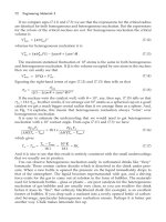
Coulson & Richardson’s
CHEMICAL ENGINEERING
VOLUME 6
Coulson & Richardson’s Chemical Engineering
Chemical Engineering, Volume 1, Sixth edition
Fluid Flow, Heat Transfer and Mass Transfer
J. M. Coulson and J. F. Richardson
with J. R. Backhurst and J. H. Harker
Chemical Engineering, Volume 2, Fifth edition
Particle Technology and Separation Processes
J. F. Richardson and J. H. Harker
with J. R. Backhurst
Chemical Engineering, Volume 3, Third edition
Chemical & Biochemical Reactors & Process Control
Edited by J. F. Richardson and D. G. Peacock
Chemical Engineering, Second edition
Solutions to the Problems in Volume 1
J. R. Backhurst and J. H. Harker with J. F. Richardson
Chemical Engineering, Solutions to the Problems
in Volumes 2 and 3
J. R. Backhurst and J. H. Harker with J. F. Richardson
Chemical Engineering, Volume 6, Fourth edition
Chemical Engineering Design
R. K. Sinnott
Coulson & Richardson’s
CHEMICAL ENGINEERING
VOLUME 6
FOURTH EDITION
Chemical Engineering Design
R. K. SINNOTT
AMSTERDAM
ž
BOSTON
ž
HEIDELBERG
ž
LONDON
ž
NEW YORK
ž
OXFORD
PARIS
ž
SAN DIEGO
ž
SAN FRANCISCO
ž
SINGAPORE
ž
SYDNEY
ž
TOKYO
Elsevier Butterworth-Heinemann
Linacre House, Jordan Hill, Oxford OX2 8DP
30 Corporate Drive, MA 01803
First published 1983
Second edition 1993
Reprinted with corrections 1994
Reprinted with revisions 1996
Third edition 1999
Reprinted 2001, 2003
Fourth edition 2005
Copyright 1993, 1996, 1999, 2005 R. K. Sinnott. All rights reserved
The right of R. K. Sinnott to be identified as the author of this work
has been asserted in accordance with the Copyright, Designs and
Patents Act 1988
No part of this publication may be reproduced in any material form (including
photocopying or storing in any medium by electronic means and whether
or not transiently or incidentally to some other use of this publication) without
the written permission of the copyright holder except in accordance with the
provisions of the Copyright, Designs and Patents Act 1988 or under the terms of
a licence issued by the Copyright Licensing Agency Ltd, 90 Tottenham Court Road,
London, England W1T 4LP. Applications for the copyright holder’s written
permission to reproduce any part of this publication should be addressed
to the publisher
Permissions may be sought directly from Elsevier’s Science & Technology Rights
Department in Oxford, UK: phone: (C44) (0)1865 843830; fax: (C44) (0)1865 853333;
e-mail: You may also complete your request on-line via
the Elsevier homepage (), by selecting ‘Customer Support’
and then ‘Obtaining Permissions’
British Library Cataloguing in Publication Data
A catalogue record for this book is available from the British Library
Library of Congress Cataloguing in Publication Data
A catalogue record for this book is available from the Library of Congress
ISBN 0 7506 6538 6
For information on all Elsevier Butterworth-Heinemann
publications visit our website at
Typeset by Laserwords Private Limited, Chennai, India
Contents
PREFACE TO FOURTH EDITION xvii
P
REFACE TO THIRD EDITION xx
P
REFACE TO SECOND EDITION xxi
P
REFACE TO FIRST EDITION xxiii
S
ERIES EDITOR’S PREFACE xxiv
A
CKNOWLEDGEMENT xxv
1 Introduction to Design 1
1.1 Introduction 1
1.2 Nature of design 1
1.2.1 The design objective (the need) 3
1.2.2 Data collection 3
1.2.3 Generation of possible design solutions 3
1.2.4 Selection 4
1.3 The anatomy of a chemical manufacturing process 5
1.3.1 Continuous and batch processes 7
1.4 The organisation of a chemical engineering project 7
1.5 Project documentation 10
1.6 Codes and standards 12
1.7 Factors of safety (design factors) 13
1.8 Systems of units 14
1.9 Degrees of freedom and design variables. The mathematical representation
of the design problem
15
1.9.1 Information flow and design variables 15
1.9.2 Selection of design variables 19
1.9.3 Information flow and the structure of d esign p roblems 20
1.10 Optimisation 24
1.10.1 General procedure 25
1.10.2 Simple models 25
1.10.3 Multiple variable problems 27
1.10.4 Linear programming 29
1.10.5 Dynamic programming 29
1.10.6 Optimisation of batch and semicontinuous processes 29
1.11 References 30
1.12 Nomenclature 31
1.13 Problems 32
2 Fundamentals of Material Balances 34
2.1 Introduction 34
2.2 The equivalence of mass and energy 34
2.3 Conservation of mass 34
2.4 Units used to express compositions 35
2.5 Stoichiometry 36
v
vi CONTENTS
2.6 Choice of system boundary 37
2.7 Choice of basis for calculations 40
2.8 Number of independent components 40
2.9 Constraints on flows and compositions 41
2.10 General algebraic method 42
2.11 Tie components 44
2.12 Excess reagent 46
2.13 Conversion and yield 47
2.14 Recycle processes 50
2.15 Purge 52
2.16 By-pass 53
2.17 Unsteady-state calculations 54
2.18 General procedure for material-balance problems 56
2.19 References (Further Reading) 57
2.20 Nomenclature 57
2.21 Problems 57
3 Fundamentals of Energy Balances (and Energy Utilisation) 60
3.1 Introduction 60
3.2 Conservation of energy 60
3.3 Forms of energy (per unit mass of material) 61
3.3.1 Potential energy 61
3.3.2 Kinetic energy 61
3.3.3 Internal energy 61
3.3.4 Work 61
3.3.5 Heat 62
3.3.6 Electrical energy 62
3.4 The energy balance 62
3.5 Calculation of specific enthalpy 67
3.6 Mean heat capacities 68
3.7 The effect of pressure on heat capacity 70
3.8 Enthalpy of mixtures 71
3.8.1 Integral heats of solution 72
3.9 Enthalpy-concentration diagrams 73
3.10 Heats of reaction 75
3.10.1 Effect of pressure on heats of reaction 77
3.11 Standard heats of formation 79
3.12 Heats of combustion 80
3.13 Compression and expansion of gases 81
3.13.1 Mollier diagrams 82
3.13.2 Polytropic compression and expansion 8 4
3.13.3 Multistage compressors 90
3.13.4 Electrical drives 93
3.14 Energy balance calculations 93
3.15 Unsteady state energy balances 99
3.16 Energy recovery 101
3.16.1 Heat exchange 101
3.16.2 Heat-exchanger networks 101
3.16.3 Waste-heat boilers 102
3.16.4 High-temperature reactors 103
3.16.5 Low-grade fuels 105
3.16.6 High-pressure process streams 107
3.16.7 Heat pumps 110
3.17 Process integration and pinch technology 111
3.17.1 Pinch technology 111
3.17.2 The problem table method 115
3.17.3 The heat exchanger network 117
3.17.4 Minimum number of exchangers 121
3.17.5 Threshold problems 123
CONTENTS vii
3.17.6 Multiple pinches and multiple utilities 124
3.17.7 Process integration: integration of other process operations 124
3.18 References 127
3.19 Nomenclature 128
3.20 Problems 130
4 Flow-sheeting 133
4.1 Introduction 133
4.2 Flow-sheet presentation 133
4.2.1 Block diagrams 134
4.2.2 Pictorial representation 134
4.2.3 Presentation of stream flow-rates 134
4.2.4 Information to be included 135
4.2.5 Layout 139
4.2.6 Precision of data 139
4.2.7 Basis of the calculation 140
4.2.8 Batch processes 140
4.2.9 Services (utilities) 140
4.2.10 Equipment identification 140
4.2.11 Computer aided drafting 140
4.3 Manual flow-sheet calculations 141
4.3.1 Basis for the flow-sheet calculations 142
4.3.2 Flow-sheet calculations on individual units 143
4.4 Computer-aided flow-sheeting 168
4.5 Full steady-state simulation programs 168
4.5.1 Information flow diagrams 171
4.6 Manual calculations with recycle streams 172
4.6.1 The split-fraction concept 172
4.6.2 Illustration of the method 176
4.6.3 Guide rules for estimating split-fraction coefficients 185
4.7 References 187
4.8 Nomenclature 188
4.9 Problems 188
5 Piping and Instrumentation 194
5.1 Introduction 194
5.2 The P and I diagram 194
5.2.1 Symbols and layout 195
5.2.2 Basic symbols 195
5.3 Valve selection 197
5.4 Pumps 199
5.4.1 Pump selection 199
5.4.2 Pressure drop in pipelines 201
5.4.3 Power requirements for pumping liquids 206
5.4.4 Characteristic curves for centrifugal pumps 208
5.4.5 System curve (operating line) 210
5.4.6 Net positive suction head (NPSH) 212
5.4.7 Pump and other shaft seals 213
5.5 Mechanical design of piping systems 216
5.5.1 Wall thickness: pipe schedule 216
5.5.2 Pipe supports 217
5.5.3 Pipe fittings 217
5.5.4 Pipe stressing 217
5.5.5 Layout and design 218
5.6 Pipe size selection 218
5.7 Control and instrumentation 227
5.7.1 Instruments 227
5.7.2 Instrumentation and control objectives 227
5.7.3 Automatic-control schemes 228
viii CONTENTS
5.8 Typical control systems 229
5.8.1 Level control 229
5.8.2 Pressure control 229
5.8.3 Flow control 229
5.8.4 Heat exchangers 230
5.8.5 Cascade control 231
5.8.6 Ratio control 231
5.8.7 Distillation column control 231
5.8.8 Reactor control 233
5.9 Alarms and safety trips, and interlocks 235
5.10 Computers and microprocessors in process control 236
5.11 References 238
5.12 Nomenclature 239
5.13 Problems 240
6 Costing and Project Evaluation 243
6.1 Introduction 243
6.2 Accuracy and purpose of capital cost estimates 243
6.3 Fixed and working capital 244
6.4 Cost escalation (inflation) 245
6.5 Rapid capital cost estimating methods 247
6.5.1 Historical costs 247
6.5.2 Step counting methods 249
6.6 The factorial method of cost estimation 250
6.6.1 Lang factors 251
6.6.2 Detailed factorial estimates 251
6.7 Estimation of purchased equipment costs 253
6.8 Summary of the factorial method 260
6.9 Operating costs 260
6.9.1 Estimation of operating costs 261
6.10 Economic evaluation of projects 270
6.10.1 Cash flow and cash-flow diagrams 270
6.10.2 Tax and depreciation 272
6.10.3 Discounted cash flow (time value of money) 272
6.10.4 Rate of return calculations 273
6.10.5 Discounted cash-flow rate of return (DCFRR) 273
6.10.6 Pay-back time 274
6.10.7 Allowing for inflation 274
6.10.8 Sensitivity analysis 274
6.10.9 Summary 275
6.11 Computer methods for costing and project evaluation 278
6.12 References 279
6.13 Nomenclature 279
6.14 Problems 280
7 Materials of Construction 284
7.1 Introduction 284
7.2 Material properties 284
7.3 Mechanical properties 285
7.3.1 Tensile strength 285
7.3.2 Stiffness 285
7.3.3 Toughness 286
7.3.4 Hardness 286
7.3.5 Fatigue 286
7.3.6 Creep 287
7.3.7 Effect of temperature on the mechanical properties 287
7.4 Corrosion resistance 287
7.4.1 Uniform corrosion 288
7.4.2 Galvanic corrosion 289
CONTENTS ix
7.4.3 Pitting 290
7.4.4 Intergranular corrosion 290
7.4.5 Effect of stress 290
7.4.6 Erosion-corrosion 291
7.4.7 High-temperature oxidation 291
7.4.8 Hydrogen embrittlement 292
7.5 Selection for corrosion resistance 292
7.6 Material costs 293
7.7 Contamination 294
7.7.1 Surface finish 295
7.8 Commonly used materials of construction 295
7.8.1 Iron and steel 295
7.8.2 Stainless steel 296
7.8.3 Nickel 298
7.8.4 Monel 299
7.8.5 Inconel 299
7.8.6 The Hastelloys 299
7.8.7 Copper and copper alloys 299
7.8.8 Aluminium and its alloys 299
7.8.9 Lead 300
7.8.10 Titanium 300
7.8.11 Tantalum 300
7.8.12 Zirconium 300
7.8.13 Silver 301
7.8.14 Gold 301
7.8.15 Platinum 301
7.9 Plastics as materials of construction for chemical plant 301
7.9.1 Poly-vinyl chloride (PVC) 302
7.9.2 Polyolefines 302
7.9.3 Polytetrafluroethylene (PTFE) 302
7.9.4 Polyvinylidene fluoride (PVDF) 302
7.9.5 Glass-fibre reinforced plastics (GRP) 302
7.9.6 Rubber 303
7.10 Ceramic materials (silicate materials) 303
7.10.1 Glass 304
7.10.2 Stoneware 304
7.10.3 Acid-resistant bricks and tiles 304
7.10.4 Refractory materials (refractories) 304
7.11 Carbon 305
7.12 Protective coatings 305
7.13 Design for corrosion resistance 305
7.14 References 305
7.15 Nomenclature 307
7.16 Problems 307
8 Design Information and Data 309
8.1 Introduction 309
8.2 Sources of information on manufacturing processes 309
8.3 General sources of physical properties 311
8.4 Accuracy required of engineering data 312
8.5 Prediction of physical properties 313
8.6 Density 314
8.6.1 Liquids 314
8.6.2 Gas and vapour density (specific volume) 315
8.7 Viscosity 316
8.7.1 Liquids 316
8.7.2 Gases 320
8.8 Thermal conductivity 320
8.8.1 Solids 320
8.8.2 Liquids 321
x CONTENTS
8.8.3 Gases 321
8.8.4 Mixtures 322
8.9 Specific heat capacity 322
8.9.1 Solids and liquids 322
8.9.2 Gases 325
8.10 Enthalpy of vaporisation (latent heat) 328
8.10.1 Mixtures 329
8.11 Vapour pressure 330
8.12 Diffusion coefficients (diffusivities) 331
8.12.1 Gases 331
8.12.2 Liquids 333
8.13 Surface tension 335
8.13.1 Mixtures 335
8.14 Critical constants 336
8.15 Enthalpy of reaction and enthalpy of formation 339
8.16 Phase equilibrium data 339
8.16.1 Experimental data 339
8.16.2 Phase equilibria 339
8.16.3 Equations of state 341
8.16.4 Correlations for liquid phase activity coefficients 342
8.16.5 Prediction of vapour-liquid equilibria 346
8.16.6 K -values for hydrocarbons 348
8.16.7 Sour-water systems (Sour) 348
8.16.8 Vapour-liquid equilibria at high pressures 348
8.16.9 Liquid-liquid equilibria 348
8.16.10 Choice of phase equilibria for design calculations 350
8.16.11 Gas solubilities 351
8.16.12 Use of equations of state to estimate specific enthalpy and density 353
8.17 References 353
8.18 Nomenclature 357
8.19 Problems 358
9 Safety and Loss Prevention 360
9.1 Introduction 360
9.2 Intrinsic and extrinsic safety 361
9.3 The hazards 361
9.3.1 Toxicity 361
9.3.2 Flammability 363
9.3.3 Explosions 365
9.3.4 Sources of ignition 366
9.3.5 Ionising radiation 368
9.3.6 Pressure 368
9.3.7 Temperature deviations 369
9.3.8 Noise 370
9.4 Dow fire and explosion index 371
9.4.1 Calculation of the Dow F & EI 371
9.4.2 Potential loss 375
9.4.3 Basic preventative and protective measures 377
9.4.4 Mond fire, explosion, and toxicity index 378
9.4.5 Summary 379
9.5 Hazard and operability studies 381
9.5.1 Basic principles 382
9.5.2 Explanation of guide words 383
9.5.3 Procedure 384
9.6 Hazard analysis 389
9.7 Acceptable risk and safety priorities 390
9.8 Safety check lists 392
9.9 Major hazards 394
9.9.1 Computer software for quantitative risk analysis 395
CONTENTS xi
9.10 References 396
9.11 Problems 398
10 Equipment Selection, Specification and Design 400
10.1 Introduction 400
10.2 Separation processes 401
10.3 Solid-solid separations 401
10.3.1 Screening (sieving) 401
10.3.2 Liquid-solid cyclones 404
10.3.3 Hydroseparators and sizers (classifiers) 405
10.3.4 Hydraulic jigs 405
10.3.5 Tables 405
10.3.6 Classifying centrifuges 406
10.3.7 Dense-medium separators (sink and float processes) 406
10.3.8 Flotation separators (froth-flotation) 407
10.3.9 Magnetic separators 407
10.3.10 Electrostatic separators 408
10.4 Liquid-solid (solid-liquid) separators 408
10.4.1 Thickeners and clarifiers 408
10.4.2 Filtration 409
10.4.3 Centrifuges 415
10.4.4 Hydrocyclones (liquid-cyclones) 422
10.4.5 Pressing (expression) 426
10.4.6 Solids drying 426
10.5 Separation of dissolved solids 434
10.5.1 Evaporators 434
10.5.2 Crystallisation 437
10.6 Liquid-liquid separation 440
10.6.1 Decanters (settlers) 440
10.6.2 Plate separators 445
10.6.3 Coalescers 445
10.6.4 Centrifugal separators 446
10.7 Separation of dissolved liquids 446
10.7.1 Solvent extraction and leaching 447
10.8 Gas-solids separations (gas cleaning) 448
10.8.1 Gravity settlers (settling chambers) 448
10.8.2 Impingement separators 448
10.8.3 Centrifugal separators (cyclones) 450
10.8.4 Filters 458
10.8.5 Wet scrubbers (washing) 459
10.8.6 Electrostatic precipitators 459
10.9 Gas
liquid separators 460
10.9.1 Settling velocity 461
10.9.2 Vertical separators 461
10.9.3 Horizontal separators 463
10.10 Crushing and grinding (comminution) equipment 465
10.11 Mixing equipment 468
10.11.1 Gas mixing 468
10.11.2 Liquid mixing 468
10.11.3 Solids and pastes 476
10.12 Transport and storage of materials 476
10.12.1 Gases 477
10.12.2 Liquids 479
10.12.3 Solids 481
10.13 Reactors 482
10.13.1 Principal types of reactor 483
10.13.2 Design procedure 486
10.14 References 486
10.15 Nomenclature 490
10.16 Problems 491
xii CONTENTS
11 Separation Columns (Distillation, Absorption and Extraction) 493
11.1 Introduction 493
11.2 Continuous distillation: process description 494
11.2.1 Reflux considerations 495
11.2.2 Feed-point location 496
11.2.3 Selection of column pressure 496
11.3 Continuous distillation: basic principles 497
11.3.1 Stage equations 497
11.3.2 Dew points and bubble points 498
11.3.3 Equilibrium flash calculations 499
11.4 Design variables in distillation 501
11.5 Design methods for binary systems 503
11.5.1 Basic equations 503
11.5.2 McCabe-Thiele method 505
11.5.3 Low product concentrations 507
11.5.4 The Smoker equations 512
11.6 Multicomponent distillation: general considerations 515
11.6.1 Key components 516
11.6.2 Number and sequencing of columns 517
11.7 Multicomponent distillation: short-cut methods for stage and reflux requirements 517
11.7.1 Pseudo-binary systems 518
11.7.2 Smith-Brinkley method 522
11.7.3 Empirical correlations 523
11.7.4 Distribution of non-key components (graphical method) 526
11.8 Multicomponent systems: rigorous solution procedures (computer methods) 542
11.8.1 Lewis-Matheson method 543
11.8.2 Thiele-Geddes method 544
11.8.3 Relaxation methods 545
11.8.4 Linear algebra methods 545
11.9 Other distillation systems 546
11.9.1 Batch distillation 546
11.9.2 Steam distillation 546
11.9.3 Reactive distillation 547
11.10 Plate efficiency 547
11.10.1 Prediction of plate efficiency 548
11.10.2 O’Connell’s correlation 550
11.10.3 Van Winkle’s correlation 552
11.10.4 AIChE method 553
11.10.5 Entrainment 556
11.11 Approximate column sizing 557
11.12 Plate contactors 557
11.12.1 Selection of plate type 560
11.12.2 Plate construction 561
11.13 Plate hydraulic design 565
11.13.1 Plate-design procedure 567
11.13.2 Plate areas 567
11.13.3 Diameter 567
11.13.4 Liquid-flow arrangement 569
11.13.5 Entrainment 570
11.13.6 Weep point 571
11.13.7 Weir liquid crest 572
11.13.8 Weir dimensions 572
11.13.9 Perforated area 572
11.13.10 Hole size 573
11.13.11 Hole pitch 574
11.13.12 Hydraulic gradient 574
11.13.13 Liquid throw 575
11.13.14 Plate pressure drop 575
11.13.15 Downcomer design [back-up] 577
11.14 Packed columns 587
11.14.1 Types of packing 589
CONTENTS xiii
11.14.2 Packed-bed height 593
11.14.3 Prediction of the height of a transfer unit (HTU) 597
11.14.4 Column diameter (capacity) 602
11.14.5 Column internals 609
11.14.6 Wetting rates 616
11.15 Column auxiliaries 616
11.16 Solvent extraction (liquid
liquid extraction) 617
11.16.1 Extraction equipment 617
11.16.2 Extractor design 618
11.16.3 Extraction columns 623
11.16.4 Supercritical fluid extraction 624
11.17 References 624
11.18 Nomenclature 627
11.19 Problems 630
12 Heat-transfer Equipment 634
12.1 Introduction 634
12.2 Basic design procedure and theory 635
12.2.1 Heat exchanger analysis: the effectiveness
NTU method 636
12.3 Overall heat-transfer coefficient 636
12.4 Fouling factors (dirt factors) 638
12.5 Shell and tube exchangers: construction details 640
12.5.1 Heat-exchanger standards and codes 644
12.5.2 Tubes 645
12.5.3 Shells 647
12.5.4 Tube-sheet layout (tube count) 647
12.5.5 Shell types (passes) 649
12.5.6 Shell and tube designation 649
12.5.7 Baffles 650
12.5.8 Support plates and tie rods 652
12.5.9 Tube sheets (plates) 652
12.5.10 Shell and header nozzles (branches) 653
12.5.11 Flow-induced tube vibrations 653
12.6 Mean temperature difference (temperature driving force) 655
12.7 Shell and tube exchangers: general design considerations 660
12.7.1 Fluid allocation: shell or tubes 660
12.7.2 Shell and tube fluid velocities 660
12.7.3 Stream temperatures 661
12.7.4 Pressure drop 661
12.7.5 Fluid physical properties 661
12.8 Tube-side heat-transfer coefficient and pressure drop (single phase) 662
12.8.1 Heat transfer 662
12.8.2 Tube-side pressure drop 666
12.9 Shell-side heat-transfer and pressure drop (single phase) 669
12.9.1 Flow pattern 669
12.9.2 Design methods 670
12.9.3 Kern’s method 671
12.9.4 Bell’s method 693
12.9.5 Shell and bundle geometry 702
12.9.6 Effect of fouling on p ressure drop 705
12.9.7 Pressure-drop limitations 705
12.10 Condensers 709
12.10.1 Heat-transfer fundamentals 710
12.10.2 Condensation outside horizontal tubes 710
12.10.3 Condensation inside and outside vertical tubes 711
12.10.4 Condensation inside horizontal tubes 716
12.10.5 Condensation of steam 717
12.10.6 Mean temperature difference 717
12.10.7 Desuperheating and sub-cooling 717
xiv CONTENTS
12.10.8 Condensation of mixtures 719
12.10.9 Pressure drop in condensers 723
12.11 Reboilers and vaporisers 728
12.11.1 Boiling heat-transfer fundamentals 731
12.11.2 Pool boiling 732
12.11.3 Convective boiling 735
12.11.4 Design of forced-circulation reboilers 740
12.11.5 Design of thermosyphon reboilers 741
12.11.6 Design of kettle reboilers 750
12.12 Plate heat exchangers 756
12.12.1 Gasketed plate heat exchangers 756
12.12.2 Welded plate 764
12.12.3 Plate-fin 764
12.12.4 Spiral heat exchangers 765
12.13 Direct-contact heat exchangers 766
12.14 Finned tubes 767
12.15 Double-pipe heat exchangers 768
12.16 Air-cooled exchangers 769
12.17 Fired heaters (furnaces and boilers) 769
12.17.1 Basic construction 770
12.17.2 Design 771
12.17.3 Heat transfer 772
12.17.4 Pressure drop 774
12.17.5 Process-side heat transfer and pressure drop 774
12.17.6 Stack design 774
12.17.7 Thermal efficiency 775
12.18 Heat transfer to vessels 775
12.18.1 Jacketed vessels 775
12.18.2 Internal coils 777
12.18.3 Agitated vessels 778
12.19 References 782
12.20 Nomenclature 786
12.21 Problems 790
13 Mechanical Design of Process Equipment 794
13.1 Introduction 794
13.1.1 Classification of pressure vessels 795
13.2 Pressure vessel codes and standards 795
13.3 Fundamental principles and equations 796
13.3.1 Principal stresses 796
13.3.2 Theories of failure 797
13.3.3 Elastic stability 798
13.3.4 Membrane stresses in shells of revolution 798
13.3.5 Flat plates 805
13.3.6 Dilation of vessels 809
13.3.7 Secondary stresses 809
13.4 General design considerations: pressure vessels 810
13.4.1 Design pressure 810
13.4.2 Design temperature 810
13.4.3 Materials 811
13.4.4 Design stress (nominal design strength) 811
13.4.5 Welded joint efficiency, and construction categories 812
13.4.6 Corrosion allowance 813
13.4.7 Design loads 814
13.4.8 Minimum practical wall thickness 814
13.5 The design of thin-walled vessels under internal pressure 815
13.5.1 Cylinders and spherical shells 815
13.5.2 Heads and closures 815
13.5.3 Design of flat ends 817
13.5.4 Design of domed ends 818
13.5.5 Conical sections and end closures 819
CONTENTS xv
13.6 Compensation for openings and branches 822
13.7 Design of vessels subject to external pressure 825
13.7.1 Cylindrical shells 825
13.7.2 Design of stiffness rings 828
13.7.3 Vessel heads 829
13.8 Design of vessels subject to combined loading 831
13.8.1 Weight loads 835
13.8.2 Wind loads (tall vessels) 837
13.8.3 Earthquake loading 839
13.8.4 Eccentric loads (tall vessels) 840
13.8.5 Torque 841
13.9 Vessel supports 844
13.9.1 Saddle supports 844
13.9.2 Skirt supports 848
13.9.3 Bracket supports 856
13.10 Bolted flanged joints 858
13.10.1 Types of flange, and selection 858
13.10.2 Gaskets 859
13.10.3 Flange faces 861
13.10.4 Flange design 862
13.10.5 Standard flanges 865
13.11 Heat-exchanger tube-plates 867
13.12 Welded joint design 869
13.13 Fatigue assessment of vessels 872
13.14 Pressure tests 872
13.15 High-pressure vessels 873
13.15.1 Fundamental equations 873
13.15.2 Compound vessels 877
13.15.3 Autofrettage 878
13.16 Liquid storage tanks 879
13.17 Mechanical design of centrifuges 879
13.17.1 Centrifugal pressure 879
13.17.2 Bowl and spindle motion: critical speed 881
13.18 References 883
13.19 Nomenclature 885
13.20 Problems 889
14 General Site Considerations 892
14.1 Introduction 892
14.2 Plant location and site selection 892
14.3 Site layout 894
14.4 Plant layout 896
14.4.1 Techniques used in site and plant layout 897
14.5 Utilities 900
14.6 Environmental considerations 902
14.6.1 Waste management 902
14.6.2 Noise 905
14.6.3 Visual impact 905
14.6.4 Legislation 905
14.6.5 Environmental auditing 906
14.7 References 906
APPENDIX A: GRAPHICAL SYMBOLS FOR PIPING SYSTEMS AND PLANT 908
A
PPENDIX B: CORROSION CHART 917
A
PPENDIX C: PHYSICAL PROPERTY DATA BANK 937
A
PPENDIX D: CONVERSION FACTORS FOR SOME COMMON SI UNITS 958
xvi CONTENTS
APPENDIX E: STANDARD FLANGES 960
A
PPENDIX F: DESIGN PROJECTS 965
A
PPENDIX G: EQUIPMENT SPECIFICATION (DATA )SHEETS 990
A
PPENDIX H: TYPICAL SHELL AND TUBE HEAT EXCHANGER TUBE-SHEET LAYOUTS 1002
A
UTHOR INDEX 1007
S
UBJECT INDEX 1017
CHAPTER 1
Introduction to Design
1.1. INTRODUCTION
This chapter is an introduction to the nature and methodology of the design process, and
its application to the design of chemical manufacturing processes.
1.2. NATURE OF DESIGN
This section is a general, somewhat philosophical, discussion of the design process; how a
designer works. The subject of this book is chemical engineering design, but the method-
ology of design described in this section a pplies equally to other branches of engineering
design.
Design is a creative activity, and as such can be one of the most rewarding and satisfying
activities undertaken by an engineer. It is the synthesis, the putting together, of ideas to
achieve a desired purpose. The design does not exist at the commencement of the project.
The designer starts with a specific objective in mind, a need, and by developing and
evaluating possible designs, arrives at what he considers the best way of achieving that
objective; be it a better chair, a new bridge, or for the chemical engineer, a new chemical
product or a stage in the design of a production process.
When considering possible ways of achieving the objective the designer will be
constrained by many factors, which will narrow down the number of possible designs;
but, there will rarely be just one possible solution to the problem, just one design. Several
alternative ways of meeting the objective will normally be possible, even several best
designs, depending on the nature of the constraints.
These constraints on the possible solutions to a problem in design arise in many ways.
Some constraints will be fixed, invariable, such as those that arise from physical laws,
government regulations, and standards. Others will be less rigid, and will be capable of
relaxation by the designer as part of his general strategy in seeking the best design. The
constraints that are outside the designer’s influence can be termed the external constraints.
These set the outer boundary of possible designs; as shown in Figure 1.1. Within this
boundary there will be a number of plausible designs bounded by the other constraints,
the internal constraints, over which the designer has some control; such as, choice of
process, choice of process conditions, materials, equipment.
Economic considerations are obviously a major constraint on any engineering design:
plants must make a profit.
Time will also be a constraint. The time available for completion of a design will
usually limit the number of alternative designs that can be considered.
1
2 CHEMICAL ENGINEERING
Plausible
designs
Government controls
Economic constraints
Safety regulations
Resources
Physical laws
Standards and codes
Personnel
Materials
Process
conditions
Choice of
process
Methods
Time
“External” constraints
“Internal” constraints
Region of all designs
Possible designs
Figure 1.1. Design constraints
Objective
(design
specification)
Collection of data,
physical
properties design
methods
Generation of
possible designs
Selection and
evaluation
(optimisation)
Final
design
Figure 1.2. The design process
The stages in the development of a design, from the initial identification of the objective
to the final design, are shown diagrammatically in Figure 1.2. Each stage is discussed in
the following sections.
Figure 1.2 shows design a s an iterative procedure; as the design develops the designer
will be aware of more possibilities and more constraints, and will be constantly seeking
new data and ideas, and evaluating possible design solutions.
INTRODUCTION TO DESIGN 3
1.2.1. The design objective (the need)
Chaddock (1975) defined design as, the conversion of an ill-defined requirement into a
satisfied customer.
The designer is creating a design for an article, or a manufacturing process, to fulfil a
particular need. In the design of a chemical process, the need is the public need for the
product, the commercial opportunity, as foreseen by the sales and marketing organisation.
Within this overall objective the designer will recognise sub-objectives; the requirements
of the various units that make up the overall process.
Before starting work the designer should obtain as complete, and as unambiguous, a
statement of the requirements as possible. If the requirement (need) arises from outside the
design group, from a client or from a nother department, then he will have to elucidate the
real requirements through discussion. It is important to distinguish between the real needs
and the wants. The wants are those parts of the initial specification that may be thought
desirable, but which can be relaxed if required as the design develops. For example, a
particular product specification may be considered desirable by the sales department, but
may be difficult and costly to obtain, and some relaxation of the specification may be
possible, producing a saleable but cheaper product. Whenever he is in a position to do so,
the designer should always question the design requirements (the project and equipment
specifications) and keep them under review as the design progresses.
Where he writes specifications for others, such as for the mechanical design or purchase
of a piece of equipment, he should be aware of the restrictions (constraints) he is placing
on other designers. A tight, well-thought-out, comprehensive, specification of the require-
ments defines the external constraints within which the other designers must work.
1.2.2. Data collection
To proceed with a design, the designer must fi rst assemble all the relevant facts a nd
data required. For process design this will include information on possible processes,
equipment performance, and physical property data. This stage can be one of the most
time consuming, and frustrating, aspects of design. Sources of process information and
physical properties are reviewed in Chapter 8.
Many design organisations will prepare a basic data manual, containing all the process
“know-how” on which the design is to be based. Most organisations will have design
manuals covering preferred methods and data for the more frequently used, routine, design
procedures.
The national standards are also sources of design methods and data; they are also design
constraints.
The constraints, particularly the external constraints, should be identified early in the
design process.
1.2.3. Generation of possible design solutions
The creative part of the design process is the generation of possible solutions to the
problem (ways of meeting the objective) for analysis, evaluation and selection. In this
activity the designer will largely rely on previous experience, his own and that of others.
4 CHEMICAL ENGINEERING
It is doubtful if a ny design is entirely novel. The antecedence of most designs can usually
be easily traced. The first motor cars were c learly horse-drawn carriages without the
horse; and the development of the design of the modern car can be traced step by step
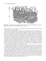
from these early prototypes. In the chemical industry, modern distillation processes have
developed from the ancient stills used for rectification of spirits; and the packed columns
used for gas absorption have developed from primitive, brushwood-packed towers. So,
it is not often that a process designer is faced with the task of producing a design for a
completely novel process or piece of equipment.
The experienced engineer will wisely prefer the tried and tested methods, rather than
possibly more exciting but untried novel designs. The work required to develop new
processes, and the cost, is usually underestimated. Progress is made more surely in small
steps. However, whenever innovation is wanted, previous experience, through prejudice,
can inhibit the generation and acceptance of new ideas; the “not invented here” syndrome.
The amount of work, and the way it is tackled, will depend on the degree of novelty
in a design project.
Chemical engineering projects can be divided into three types, depending on the novelty
involved:
1. Modifications, and additions, to existing plant; usually carried out by the plant design
group.
2. New production capacity to meet growing sales demand, and the sale of established
processes by contractors. Repetition of existing designs, with only minor design
changes.
3. New processes, developed from laboratory research, through pilot plant, to a
commercial process. Even here, most of the unit operations and process equipment
will use established designs.
The first step in devising a new process design will be to sketch out a rough block
diagram showing the main stages in the process; and to list the primary function (objective)
and the major constraints for each stage. Experience should then indicate what types of
unit operations and equipment should be considered.
Jones (1970) discusses the methodology of design, and reviews some of the special
techniques, such as brainstorming sessions and synectics, that have been developed to
help generate ideas for solving intractable problems. A good general reference on the art
of problem solving is the classical work by Polya (1957); see also Chittenden (1987).
Some techniques for problem solving in the Chemical Industry are covered in a short text
by Casey and Frazer (1984).
The generation of ideas for possible solutions to a design problem cannot be separated
from the selection stage of the design process; some ideas will be rejected as impractical
as soon as they are conceived.
1.2.4. Selection
The designer starts with the set of all possible solutions bounded by the external
constraints, and by a process of progressive evaluation and selection, narrows down the
range of candidates to find the “best” design for the purpose.
INTRODUCTION TO DESIGN 5
The selection process can be considered to go through the following stages:
Possible designs (credible)
within the external constraints.
Plausible designs (feasible)
within the internal constraints.
Probable designs
likely candidates.
Best design (optimum)
judged the best solution to the problem.
The selection process will become more detailed and more refined as the design progresses
from the area of possible to the area of probable solutions. In the early stages a coarse
screening based on common sense, engineering judgement, and rough costings will usually
suffice. For example, it would not take many minutes to narrow down the choice of raw
materials f or the manufacture of ammonia from the possible candidates of, say, wood,
peat, coal, natural gas, and oil, to a choice of between gas and oil, but a more detailed
study would be needed to choose between oil and gas. To select the best design from the
probable designs, detailed design work and costing will usually be necessary. However,
where the performance of candidate designs is likely to be close the cost of this further
refinement, in time and money, may not be worthwhile, particularly as there will usually
be some uncertainty in the accuracy of the estimates.
The mathematical techniques that have been developed to assist in the optimisation of
designs, and plant performance, are discussed briefly in Section 1.10.
Rudd and Watson (1968) and Wells (1973) describe formal techniques for the prelim-
inary screening of alternative designs.
1.3. THE ANATOMY OF A CHEMICAL MANUFACTURING
PROCESS
The basic components of a typical chemical process are shown in Figure 1.3, in which
each block represents a stage in the overall process for producing a product from the raw
materials. Figure 1.3 represents a generalised process; not all the stages will be needed for
any particular process, and the complexity of each stage will depend on the nature of the
process. Chemical engineering design is concerned with the selection and arrangement
of the stages, and the selection, specification and design of the equipment required to
perform the stage functions.
Raw
material
storage
Feed
preparation
Reaction
Product
separation
Product
purification
Product
storage
Sales
Recycle of unreacted
material
By-products
Wastes
Stage 1 Stage 2 Stage 3 Stage 4 Stage 5 Stage 6
Figure 1.3. Anatomy of a chemical process
Stage 1. Raw material storage
Unless the r aw materials (also called essential materials, or feed stocks) are supplied
as intermediate products (intermediates) from a neighbouring plant, some provision will
6 CHEMICAL ENGINEERING
have to be made to hold several days, or weeks, storage to smooth out fluctuations and
interruptions in supply. Even when the materials come from an adjacent plant some
provision is usually made to hold a few hours, or even days, supply to decouple the
processes. The storage required will depend on the nature of the raw materials, the method
of delivery, and what assurance can be placed on the continuity of supply. If materials are
delivered by ship (tanker or bulk carrier) several weeks stocks may be necessary; whereas
if they are received by road or rail, in smaller lots, less storage will be needed.
Stage 2. Feed preparation
Some purification, and preparation, of the raw materials will usually be necessary before
they are sufficiently pure, or in the right form, to be fed to the reaction stage. For example,
acetylene generated by the carbide process contains arsenical and sulphur compounds, and
other impurities, which must be removed by scrubbing with concentrated sulphuric acid
(or other processes) before it is sufficiently pure for reaction with hydrochloric acid to
produce dichloroethane. Liquid feeds will need to be vaporised before being f ed to gas-
phase reactors, and solids may need crushing, grinding and screening.
Stage 3. Reactor
The reaction stage is the heart of a chemical manufacturing process. In the reactor the
raw materials are brought together under conditions that promote the production of the
desired product; invariably, by-products and unwanted compounds (impurities) will also
be formed.
Stage 4. Product separation
In this first stage after the reactor the products and by-products are separated from any
unreacted material. If in sufficient quantity, the unreacted material will be recycled to
the reactor. They may be returned directly to the reactor, or to the feed purification and
preparation stage. The by-products may also be separated from the products at this stage.
Stage 5. Purification
Before sale, the main product will usually need purification to meet the product specifi-
cation. If produced in economic quantities, the by-products may also be purified for sale.
Stage 6. Product storage
Some inventory of finished product must be held to match production with sales. Provision
for product packaging and transport will also be needed, depending on the nature of the
product. Liquids will normally be dispatched in drums and in bulk tankers (road, rail and
sea), solids in sacks, cartons or bales.
The stock held will depend on the nature of the product and the market.
Ancillary processes
In addition to the main process stages shown in Figure 1.3, provision will have to be
made for the supply of the services (utilities) needed; such as, process water, cooling
INTRODUCTION TO DESIGN 7
water, compressed air, steam. Facilities will also be needed for maintenance, firefighting,
offices and other accommodation, and laboratories; see Chapter 14.
1.3.1. Continuous and batch processes
Continuous processes are designed to operate 24 hours a day, 7 days a week, throughout
the year. Some down time will be allowed for maintenance and, for some processes,
catalyst regeneration. The plant attainment; that is, the percentage of the available hours
in a year that the plant operates, will usually be 90 to 95%.
Attainment % D
hours operated
8760
ð 100
Batch processes are designed to operate intermittently. Some, or all, the process units
being frequently shut down and started up.
Continuous processes will usually be more economical for large scale production. Batch
processes are used where some flexibility is wanted in production rate or product speci-
fication.
Choice of continuous versus batch production
The choice between batch or continuous operation will not be clear cut, but the following
rules can be used as a guide.
Continuous
1. Production rate greater than 5 ð10
6
kg/h
2. Single product
3. No severe fouling
4. Good catalyst life
5. Proven processes design
6. Established market
Batch
1. Production rate less than 5 ð 10
6
kg/h
2. A range of products or product specifications
3. Severe fouling
4. Short catalyst life
5. New product
6. Uncertain design
1.4. THE ORGANISATION OF A CHEMICAL ENGINEERING
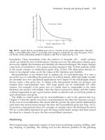
PROJECT
The design work required in the engineering of a chemical manufacturing process can be
divided into two broad phases.
Phase 1. Process design, which covers the steps from the initial selection of the process
to be used, through to the issuing of the process flow-sheets; and includes the selection,
8 CHEMICAL ENGINEERING
Project specification
Initial evaluation.
Process selection.
Preliminary flow diagrams.
Detailed process design.
Flow-sheets.
Chemical engineering equipment
design and specifications.
Reactors, Unit operations, Heat exchangers,
Miscellaneous equipment.
Materials selection.
Process manuals
Material and energy balances.
Preliminary equipment selection
and design.
Process flow-sheeting.
Preliminary cost estimation.
Authorisation of funds.
Piping and instrument design
Instrument selection
and specification
Pumps and compressors.
Selection and specification
Vessel design Heat exchanger design
Utilities and other services.
Design and specification
Electrical,
Motors, switch gear,
substations, etc.
Piping design Structural design Plant layout
General civil work.
Foundations, drains,
roads, etc.
Buildings.
Offices, laboratories,
control rooms, etc.
Project cost estimation.
Capital authorisation
Purchasing/procurement
Raw material specification.
(contracts)
Construction
Start-up
Operating manuals
Operation
Sales
Figure 1.4. The structure of a chemical engineering project