Engineering Materials Vol II (microstructures_ processing_ design) 2nd ed. - M. Ashby_ D. Jones (1999) WW Part 1 pptx
Bạn đang xem bản rút gọn của tài liệu. Xem và tải ngay bản đầy đủ của tài liệu tại đây (637.88 KB, 23 trang )
Engineering Materials 2
An Introduction to Microstructures, Processing and Design
Engineering Materials 2
An Introduction to Microstructures, Processing and Design
Second Edition
by
Michael F. Ashby
and
David R. H. Jones
Department of Engineering, Cambridge University, England
OXFORD AUCKLAND BOSTON JOHANNESBURG MELBOURNE NEW DELHI
Butterworth-Heinemann
Linacre House, Jordan Hill, Oxford OX2 8DP
225 Wildwood Avenue, Woburn, MA 01801-2041
A division of Reed Educational and Professional Publishing Ltd
A member of the Reed Elsevier plc group
First edition 1986
Reprinted with corrections 1988
Reprinted 1989, 1992
Second edition 1998
Reprinted 1999
© Michael F. Ashby and David R. H. Jones 1998
All rights reserved. No part of this publication
may be reproduced in any material form (including
photocopying or storing in any medium by electronic
means and whether or not transiently or incidentally
to some other use of this publication) without the
written permission of the copyright holder except
in accordance with the provisions of the Copyright,
Designs and Patents Act 1988 or under the terms of a
licence issued by the Copyright Licensing Agency Ltd,
90 Tottenham Court Road, London, England W1P 9HE.
Applications for the copyright holder’s written permission
to reproduce any part of this publication should be addressed
to the publishers
British Library Cataloguing in Publication Data
A catalogue record for this book is available from the British Library
Library of Congress Cataloguing in Publication Data
A catalogue record for this book is available from the Library of Congress
ISBN 0 7506 4019 7
Printed and bound in Great Britain by
Biddles Ltd, Guildford and Kingd’s Lynn
Contents
General introduction ix
A. Metals
1. Metals 3
the generic metals and alloys; iron-based, copper-based, nickel-based,
aluminium-based and titanium-based alloys; design data
2. Metal structures 14
the range of metal structures that can be altered to get different
properties: crystal and glass structure, structures of solutions and
compounds, grain and phase boundaries, equilibrium shapes of
grains and phases
3. Equilibrium constitution and phase diagrams 25
how mixing elements to make an alloy can change their structure;
examples: the lead–tin, copper–nickel and copper–zinc alloy systems
4. Case studies in phase diagrams 34
choosing soft solders; pure silicon for microchips; making bubble-free ice
5. The driving force for structural change 46
the work done during a structural change gives the driving force for the
change; examples: solidification, solid-state phase changes, precipitate
coarsening, grain growth, recrystallisation; sizes of driving forces
6. Kinetics of structural change: I – diffusive transformations 57
why transformation rates peak – the opposing claims of driving force
and thermal activation; why latent heat and diffusion slow
transformations down
7. Kinetics of structural change: II – nucleation 68
how new phases nucleate in liquids and solids; why nucleation is helped
by solid catalysts; examples: nucleation in plants, vapour trails, bubble
chambers and caramel
8. Kinetics of structural change: III – displacive transformations 76
how we can avoid diffusive transformations by rapid cooling; the
alternative – displacive (shear) transformations at the speed of sound
9. Case studies in phase transformations 89
artificial rain-making; fine-grained castings; single crystals for
semiconductors; amorphous metals
10. The light alloys 100
where they score over steels; how they can be made stronger: solution,
age and work hardening; thermal stability
11. Steels: I – carbon steels 113
structures produced by diffusive changes; structures produced by
displacive changes (martensite); why quenching and tempering can
transform the strength of steels; the TTT diagram
12. Steels: II – alloy steels 125
adding other elements gives hardenability (ease of martensite formation),
solution strengthening, precipitation strengthening, corrosion resistance,
and austenitic (f.c.c.) steels
13. Case studies in steels 133
metallurgical detective work after a boiler explosion; welding steels
together safely; the case of the broken hammer
14. Production, forming and joining of metals 143
processing routes for metals; casting; plastic working; control of grain
size; machining; joining; surface engineering
B. Ceramics and glasses
15. Ceramics and glasses 161
the generic ceramics and glasses: glasses, vitreous ceramics, high-
technology ceramics, cements and concretes, natural ceramics (rocks and
ice), ceramic composites; design data
16. Structure of ceramics 167
crystalline ceramics; glassy ceramics; ceramic alloys; ceramic micro-
structures: pure, vitreous and composite
17. The mechanical properties of ceramics 177
high stiffness and hardness; poor toughness and thermal shock
resistance; the excellent creep resistance of refractory ceramics
vi Contents
18. The statistics of brittle fracture and case study 185
how the distribution of flaw sizes gives a dispersion of strength: the
Weibull distribution; why the strength falls with time (static fatigue);
case study: the design of pressure windows
19. Production, forming and joining of ceramics 194
processing routes for ceramics; making and pressing powders to shape;
working glasses; making high-technology ceramics; joining ceramics;
applications of high-performance ceramics
20. Special topic: cements and concretes 207
historical background; cement chemistry; setting and hardening of
cement; strength of cement and concrete; high-strength cements
C. Polymers and composites
21. Polymers 219
the generic polymers: thermoplastics, thermosets, elastomers, natural
polymers; design data
22. The structure of polymers 228
giant molecules and their architecture; molecular packing: amorphous
or crystalline?
23. Mechanical behaviour of polymers 238
how the modulus and strength depend on temperature and time
24. Production, forming and joining of polymers 254
making giant molecules by polymerisation; polymer “alloys”; forming
and joining polymers
25. Composites: fibrous, particulate and foamed 263
how adding fibres or particles to polymers can improve their stiffness,
strength and toughness; why foams are good for absorbing energy
26. Special topic: wood 277
one of nature’s most successful composite materials
D. Designing with metals, ceramics, polymers and composites
27. Design with materials 289
the design-limiting properties of metals, ceramics, polymers and composites;
design methodology
Contents vii
28. Case studies in design 296
1. Designing with metals: conveyor drums for an iron ore terminal 296
2. Designing with ceramics: ice forces on offshore structures 303
3. Designing with polymers: a plastic wheel 308
4. Designing with composites: materials for violin bodies 312
Appendix 1 Teaching yourself phase diagrams 320
Appendix 2 Symbols and formulae 370
Index 377
viii Contents
understand the basic material. And finally we look at the role of materials in the
design of engineering devices, mechanisms or structures, and develop a methodology
for materials selection. One subject – Phase Diagrams – can be heavy going. We have
tried to overcome this by giving a short programmed-learning course on phase dia-
grams. If you work through this when you come to the chapter on phase diagrams you
will know all you need to about the subject. It will take you about 4 hours.
At the end of each chapter you will find a set of problems: try to do them while the
topic is still fresh in your mind – in this way you will be able to consolidate, and
develop, your ideas as you go along.
To the lecturer
This book has been written as a second-level course for engineering students. It pro-
vides a concise introduction to the microstructures and processing of materials (metals,
ceramics, polymers and composites) and shows how these are related to the properties
required in engineering design. It is designed to follow on from our first-level text on
the properties and applications of engineering materials,* but it is completely self-
contained and can be used by itself.
Each chapter is designed to provide the content of a 50-minute lecture. Each block
of four or so chapters is backed up by a set of Case Studies, which illustrate and con-
solidate the material they contain. There are special sections on design, and on such
materials as wood, cement and concrete. And there are problems for the student at the
end of each chapter for which worked solutions can be obtained separately, from the
publisher. In order to ease the teaching of phase diagrams (often a difficult topic for
engineering students) we have included a programmed-learning text which has proved
helpful for our own students.
We have tried to present the material in an uncomplicated way, and to make the
examples entertaining, while establishing basic physical concepts and their application
to materials processing. We found that the best way to do this was to identify a small
set of “generic” materials of each class (of metals, of ceramics, etc.) which broadly
typified the class, and to base the development on these; they provide the pegs on
which the discussion and examples are hung. But the lecturer who wishes to draw
other materials into the discussion should not find this difficult.
Acknowledgements
We wish to thank Prof. G. A. Chadwick for permission to reprint Fig. A1.34 (p. 340)
and K. J. Pascoe and Van Nostrand Reinhold Co. for permission to reprint Fig. A1.41
(p. 344).
x General introduction
* M. F. Ashby and D. R. H. Jones, Engineering Materials 1: An Introduction to their Properties and Applications,
2nd edition, Butterworth-Heinemann, 1996.
2 Engineering Materials 2
4 Engineering Materials 2
Fig. 1.1. A fully working model, one-sixth full size, of a steam traction engine of the type used on many
farms a hundred years ago. The model can pull an automobile on a few litres of water and a handful of coal.
But it is also a nice example of materials selection and design.
Table 1.1 Generic iron-based metals
Metal Typical composition Typical uses
(wt%)
Low-carbon (“mild”) steel Fe + 0.04 to 0.3 C Low-stress uses. General constructional steel, suitable
(+ ≈ 0.8 Mn) for welding.
Medium-carbon steel Fe + 0.3 to 0.7 C Medium-stress uses: machinery parts – nuts and
bolts,
(+ ≈ 0.8 Mn) shafts, gears.
High-carbon steel Fe + 0.7 to 1.7 C High-stress uses: springs, cutting tools, dies.
(+ ≈ 0.8 Mn)
Low-alloy steel Fe + 0.2 C 0.8 Mn High-stress uses: pressure vessels, aircraft parts.
1 Cr 2 Ni
High-alloy (“stainless”) Fe + 0.1 C 0.5 Mn High-temperature or anti-corrosion uses: chemical or
steel 18 Cr 8 Ni steam plants.
Cast iron Fe + 1.8 to 4 C Low-stress uses: cylinder blocks, drain pipes.
(+ ≈ 0.8 Mn 2 Si)
Metals 5
Fig. 1.2. A close-up of the mechanical lubricator on the traction engine. Unless the bore of the steam
cylinder is kept oiled it will become worn and scored. The lubricator pumps small metered quantities of
steam oil into the cylinder to stop this happening. The drive is taken from the piston rod by the ratchet and
pawl arrangement.
The stresses in the machinery – like the gear-wheel teeth or the drive shafts – are a
good deal higher, and these parts are made from either medium-carbon, high-carbon or
low-alloy steels to give extra strength. However, there are a few components where
even the strength of high-carbon steels as delivered “off the shelf” (σ
y
≈ 400 MPa)
is not enough. We can see a good example in the mechanical lubricator, shown in
Fig. 1.2, which is essentially a high-pressure oil metering pump. This is driven by a
ratchet and pawl. These have sharp teeth which would quickly wear if they were
made of a soft alloy. But how do we raise the hardness above that of ordinary high-
carbon steel? Well, medium- and high-carbon steels can be hardened to give a yield
strength of up to 1000 MPa by heating them to bright red heat and then quenching
them into cold water. Although the quench makes the hardened steel brittle, we can
make it tough again (though still hard) by tempering it – a process that involves heating
the steel again, but to a much lower temperature. And so the ratchet and pawls are
made from a quenched and tempered high-carbon steel.
Stainless steel is used in several places. Figure 1.3 shows the fire grate – the metal
bars which carry the burning coals inside the firebox. When the engine is working
hard the coal is white hot; then, both oxidation and creep are problems. Mild steel bars
can burn out in a season, but stainless steel bars last indefinitely.
6 Engineering Materials 2
Fig. 1.3. The fire grate, which carries the white-hot fire inside the firebox, must resist oxidation and creep.
Stainless steel is best for this application. Note also the threaded monel stays which hold the firebox sides
together against the internal pressure of the steam.
Finally, what about cast iron? Although this is rather brittle, it is fine for low-stressed
components like the cylinder block. In fact, because cast iron has a lot of carbon it has
several advantages over mild steel. Complicated components like the cylinder block
are best produced by casting. Now cast iron melts much more easily than steel (adding
carbon reduces the melting point in just the way that adding anti-freeze works with
water) and this makes the pouring of the castings much easier. During casting, the
carbon can be made to separate out as tiny particles of graphite, distributed through-
out the iron, which make an ideal boundary lubricant. Cylinders and pistons made
from cast iron wear very well; look inside the cylinders of your car engine next time
the head has to come off, and you will be amazed by the polished, almost glazed look
of the bores – and this after perhaps 10
8
piston strokes.
These, then, are the basic classes of ferrous alloys. Their compositions and uses are
summarised in Table 1.1, and you will learn more about them in Chapters 11 and 12,
but let us now look at the other generic alloy groups.
An important group of alloys are those based on copper (Table 1.2).
The most notable part of the traction engine made from copper is the boiler and its
firetubes (see Fig. 1.1). In full size this would have been made from mild steel, and the
use of copper in the model is a nice example of how the choice of material can depend
on the scale of the structure. The boiler plates of the full-size engine are about 10 mm
thick, of which perhaps only 6 mm is needed to stand the load from the pressurised
Metals 7
Table 1.2 Generic copper-based metals
Metal Typical composition (wt%) Typical uses
Copper 100 Cu Ductile, corrosion resistant and a good electrical conductor:
water pipes, electrical wiring.
Brass Zn Stronger than copper, machinable, reasonable corrosion
resistance: water fittings, screws, electrical components.
Bronze Cu + 10–30 Sn Good corrosion resistance: bearings, ships’ propellers, bells.
Cupronickel Cu + 30 Ni Good corrosion resistance, coinage.
steam safely – the other 4 mm is an allowance for corrosion. Although a model steel
boiler would stand the pressure with plates only 1 mm thick, it would still need the
same corrosion allowance of 4 mm, totalling 5 mm altogether. This would mean a very
heavy boiler, and a lot of water space would be taken up by thick plates and firetubes.
Because copper hardly corrodes in clean water, this is the obvious material to use.
Although weaker than steel, copper plates 2.5 mm thick are strong enough to resist the
working pressure, and there is no need for a separate corrosion allowance. Of course,
copper is expensive – it would be prohibitive in full size – but this is balanced by its
ductility (it is very easy to bend and flange to shape) and by its high thermal conduct-
ivity (which means that the boiler steams very freely).
Brass is stronger than copper, is much easier to machine, and is fairly corrosion-
proof (although it can “dezincify” in water after a long time). A good example of its
use in the engine is for steam valves and other boiler fittings (see Fig. 1.4). These are
intricate, and must be easy to machine; dezincification is a long-term possibility, so
occasional inspection is needed. Alternatively, corrosion can be avoided altogether by
using the more expensive bronzes, although some are hard to machine.
Nickel and its alloys form another important class of non-ferrous metals (Table 1.3).
The superb creep resistance of the nickel-based superalloys is a key factor in designing
the modern gas-turbine aero-engine. But nickel alloys even appear in a model steam
engine. The flat plates in the firebox must be stayed together to resist the internal
steam pressure (see Fig. 1.3). Some model-builders make these stays from pieces of
monel rod because it is much stronger than copper, takes threads much better and is
very corrosion resistant.
Metals for drinks cans
Few people would think that the humble drink can (Fig. 1.5) was anything special. But
to a materials engineer it is high technology. Look at the requirements. As far as
possible we want to avoid seams. The can must not leak, should use as little metal as
possible and be recyclable. We have to choose a metal that is ductile to the point that
it can be drawn into a single-piece can body from one small slug of metal. It must not
corrode in beer or coke and, of course, it must be non-toxic. And it must be light and
must cost almost nothing.
8 Engineering Materials 2
Fig. 1.4. Miniature boiler fittings made from brass: a water-level gauge, a steam valve, a pressure gauge,
and a feed-water injector. Brass is so easy to machine that it is good for intricate parts like these.
Table 1.3 Generic nickel-based metals
Metals Typical composition (wt%) Typical uses
Monels Ni + 30 Cu 1 Fe 1 Mn Strong, corrosion resistant: heat-exchanger tubes.
Superalloys Ni + 30 Cr 30 Fe 0.5 Ti 0.5 Al Creep and oxidation resistant: furnace parts.
Ni + 10 Co 10 W 9 Cr 5 A12 Ti Highly creep resistant: turbine blades and discs.
Aluminium-based metals are the obvious choice* (Table 1.4) – they are light, corro-
sion resistant and non-toxic. But it took several years to develop the process for form-
ing the can and the alloy to go with it. The end product is a big advance from the days
when drinks only came in glass bottles, and has created a new market for aluminium
(now threatened, as we shall see in Chapter 21, by polymers). Because aluminium is
* One thinks of aluminium as a cheap material – aluminium spoons are so cheap that they are thrown away.
It was not always so. Napoleon had a set of cutlery specially made from the then-new material. It cost him
more than a set of solid silver.
Metals 9
Fig. 1.5. The aluminium drink can is an innovative product. The body is made from a single slug of a
3000 series aluminium alloy. The can top is a separate pressing which is fastened to the body by a rolled
seam once the can has been filled. There
are
limits to one-piece construction.
Table 1.4 Generic aluminium-based metals
Metal Typical composition (wt%) Typical uses
1000 Series > 99 Al Weak but ductile and a good electrical
unalloyed Al conductor: power transmission lines, cooking foil.
2000 Series Al + 4 Cu + Mg, Si, Mn Strong age-hardening alloy: aircraft skins, spars,
major additive Cu forgings, rivets.
3000 Series Al + 1 Mn Moderate strength, ductile, excellent corrosion resistance:
major additive Mn roofing sheet, cooking pans, drinks can bodies.
5000 Series Al + 3 Mg 0.5 Mn Strong work-hardening weldable plate: pressure
major additive Mg vessels, ship superstructures.
6000 Series Al + 0.5 Mg 0.5 Si Moderate-strength age-hardening alloy: anodised
major additives extruded sections, e.g. window frames.
Mg + Si
7000 Series Al + 6 Zn + Mg, Cu, Mn Strong age-hardening alloy: aircraft forgings,
major additives sparts, lightweight railway carriage shells.
Zn + Mg
Casting alloys Al + 11 Si Sand and die castings.
Aluminium– Al + 3 Li Low density and good strength: aircraft skins
lithium alloys and spars.
10 Engineering Materials 2
lighter than most other metals it is also the obvious choice for transportation: aircraft,
high-speed trains, cars, even. Most of the alloys listed in Table 1.4 are designed with
these uses in mind. We will discuss the origin of their strength, and their uses, in more
detail in Chapter 10.
Metals for artificial hip joints
As a last example we turn to the world of medicine. Osteo-arthritis is an illness that
affects many people as they get older. The disease affects the joints between different
bones in the body and makes it hard – and painful – to move them. The problem is
caused by small lumps of bone which grow on the rubbing surfaces of the joints and
which prevent them sliding properly. The problem can only be cured by removing the
bad joints and putting artificial joints in their place. The first recorded hip-joint re-
placement was done as far back as 1897 – when it must have been a pretty hazardous
business – but the operation is now a routine piece of orthopaedic surgery. In fact
30,000 hip joints are replaced in the UK every year; world-wide the number must
approach half a million.
Figure 1.6 shows the implant for a replacement hip joint. In the operation, the head
of the femur is cut off and the soft marrow is taken out to make a hole down the centre
of the bone. Into the hole is glued a long metal shank which carries the artificial head.
Fig. 1.6. The titanium alloy implant for a replacement hip joint. The long shank is glued into the top of the
femur. The spherical head engages in a high-density polythene socket which is glued into the pelvic socket.
Metals 11
Table 1.5 Generic titanium-based metals
Metal Typical composition (wt%) Typical uses
a–b titanium alloy Ti–6 A14 V Light, very strong, excellent corrosion resistance, high melting
point, good creep resistance. The alloy workhorse:
turbofans, airframes, chemical plant, surgical implants.
This fits into a high-density polythene socket which in turn is glued into the old bone
socket. The requirements of the implant are stringent. It has to take large loads with-
out bending. Every time the joint is used (≈10
6
times a year) the load on it fluctuates,
giving us a high-cycle fatigue problem as well. Body fluids are as corrosive as sea
water, so we must design against corrosion, stress corrosion and corrosion fatigue. The
metal must be bio-compatible. And, ideally, it should be light as well.
The materials that best meet these tough requirements are based on titanium. The
α
–
β
alloy shown in Table 1.5 is as strong as a hardened and tempered high-carbon
steel, is more corrosion resistant in body fluids than stainless steel, but is only half
the weight. A disadvantage is that its modulus is only half that of steels, so that it
tends to be “whippy” under load. But this can be overcome by using slightly stiffer
sections. The same alloy is used in aircraft, both in the airframes and in the compressor
stages of the gas turbines which drive them.
Data for metals
When you select a metal for any design application you need data for the properties.
Table 1.6 gives you approximate property data for the main generic metals, useful for
the first phase of a design project. When you have narrowed down your choice you
should turn to the more exhaustive data compilations given under Further Reading.
Finally, before making final design decisions you should get detailed material specifica-
tions from the supplier who will provide the materials you intend to use. And if the
component is a critical one (meaning that its failure could precipitate a catastrophe)
you should arrange to test it yourself.
There are, of course, many more metals available than those listed here. It is use-
ful to know that some properties depend very little on microstructure: the density,
modulus, thermal expansion and specific heat of any steel are pretty close to those listed
in the table. (Look at the table and you will see that the variations in these properties are
seldom more than ±5%.) These are the “structure-insensitive” properties. Other proper-
ties, though, vary greatly with the heat treatment and mechanical treatment, and the
detailed alloy composition. These are the “structure-sensitive” properties: yield and
tensile strength, ductility, fracture toughness, and creep and fatigue strength. They
cannot be guessed from data for other alloys, even when the composition is almost the
same. For these it is essential to consult manufacturers’ data sheets listing the proper-
ties of the alloy you intend to use, with the same mechanical and heat treatment.
12 Engineering Materials 2
Table 1.6 Properties of the generic metals
Metal
Cost
Density Young’s Yield Tensile
(UK£ (US$) (Mg m
−
3
) modulus strength strength
tonne
−
1
) (GPa) (MPa) (MPa)
Iron 100 (140) 7.9 211 50 200
Mild steel 200–230 (260–300) 7.9 210 220 430
High-carbon steel 150 (200) 7.8 210 350–1600 650–2000
Low-alloy steels 180–250 (230–330) 7.8 203 290–1600 420–2000
High-alloy steels 1100–1400 (1400–1800) 7.8 215 170–1600 460–1700
Cast irons 120 (160) 7.4 152 50–400 10–800
Copper 1020 (1330) 8.9 130 75 220
Brasses 750–1060 (980–1380) 8.4 105 200 350
Bronzes 1500 (2000) 8.4 120 200 350
Nickel 3200 (4200) 8.9 214 60 300
Monels 3000 (3900) 8.9 185 340 680
Superalloys 5000 (6500) 7.9 214 800 1300
Aluminium 910 (1180) 2.7 71 25–125 70–135
1000 Series 910 (1180) 2.7 71 28–165 70–180
2000 Series 1100 (1430) 2.8 71 200–500 300–600
5000 Series 1000 (1300) 2.7 71 40–300 120–430
7000 Series 1100 (1430) 2.8 71 350–600 500–670
Casting alloys 1100 (1430) 2.7 71 65–350 130–400
Titanium 4630 (6020) 4.5 120 170 240
Ti–6 A14 V 5780 (7510) 4.4 115 800–900 900–1000
Zinc 330 (430) 7.1 105 120
Lead–tin solder 2000 (2600) 9.4 40
Diecasting alloy 800 (1040) 6.7 105 280–330
Further reading
Smithells’ Metals Reference Book, 7th edition, Butterworth-Heinemann, 1992 (for data).
ASM Metals Handbook, 10th edition, ASM International, 1990 (for data).
Problems
1.1 Explain what is meant by the following terms:
(a) structure-sensitive property;
(b) structure-insensitive property.
List five different structure-sensitive properties.
List four different structure-insensitive properties.
Answers: Structure-sensitive properties: yield strength, hardness, tensile strength,
ductility, fracture toughness, fatigue strength, creep strength, corrosion resistance,
Metals 13
Ductility Fracture Melting Specific Thermal Thermal
toughness temperature heat conductivity expansion
(MPa m
1/2
) (K) (J kg
−
1
K
−
1
) (W m
−
1
K
−
1
) coefficient
(MK
−
1
)
0.3 80 1809 456 78 12
0.21 140 1765 482 60 12
0.1–0.2 20–50 1570 460 40 12
0.1–0.2 50–170 1750 460 40 12
0.1–0.5 50–170 1680 500 12–30 10–18
0–0.18 6–20 1403
0.5–0.9 >100 1356 385 397 17
0.5 30–100 1190 121 20
0.5 30–100 1120 85 19
0.4 >100 1728 450 89 13
0.5 >100 1600 420 22 14
0.2 >100 1550 450 11 12
0.1–0.5 45 933 917 240 24
0.1–0.45 45 915 24
0.1–0.25 10–50 860 180 24
0.1–0.35 30–40 890 130 22
0.1–0.17 20–70 890 150 24
0.01–0.15 5–30 860 140 20
0.25 1940 530 22 9
0.1–0.2 50–80 1920 610 6 8
0.4 693 390 120 31
456
0.07–0.15 650 420 110 27
wear resistance, thermal conductivity, electrical conductivity. Structure-insensitive
properties: elastic moduli, Poisson’s ratio, density, thermal expansion coefficient,
specific heat.
1.2 What are the five main generic classes of metals? For each generic class:
(a) give one example of a specific component made from that class;
(b) indicate why that class was selected for the component.
Metal structures 15
Table 2.2 Crystal structures of pure metals at room temperature
Pure metal Structure Unit cell dimensions (nm)
ac
Aluminium f.c.c. 0.405
Beryllium c.p.h. 0.229 0.358
Cadmium c.p.h. 0.298 0.562
Chromium b.c.c. 0.289
Cobalt c.p.h. 0.251 0.409
Copper f.c.c. 0.362
Gold f.c.c. 0.408
Hafnium c.p.h. 0.320 0.506
Indium Face-centred tetragonal
Iridium f.c.c. 0.384
Iron b.c.c. 0.287
Lanthanum c.p.h. 0.376 0.606
Lead f.c.c. 0.495
Magnesium c.p.h. 0.321 0.521
Manganese Cubic 0.891
Molybdenum b.c.c. 0.315
Nickel f.c.c. 0.352
Niobium b.c.c. 0.330
Palladium f.c.c. 0.389
Platinum f.c.c. 0.392
Rhodium f.c.c. 0.380
Silver f.c.c. 0.409
Tantalum b.c.c. 0.331
Thallium c.p.h. 0.346 0.553
Tin Body-centred tetragonal
Titanium c.p.h. 0.295 0.468
Tungsten b.c.c. 0.317
Vanadium b.c.c. 0.303
Yttrium c.p.h. 0.365 0.573
Zinc c.p.h. 0.267 0.495
Zirconium c.p.h. 0.323 0.515
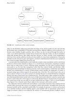
Fig. 2.1. Some metals have more than one crystal structure. The most important examples of this
polymorphism
are in iron and titanium.
16 Engineering Materials 2
back to b.c.c. at 1391°C; and titanium changes from c.p.h. to b.c.c. at 882°C. This
multiplicity of crystal structures is called polymorphism. But it is obviously out of the
question to try to control crystal structure simply by changing the temperature (iron is
useless as a structural material well below 914°C). Polymorphism can, however, be
brought about at room temperature by alloying. Indeed, many stainless steels are f.c.c.
rather than b.c.c. and, especially at low temperatures, have much better ductility and
toughness than ordinary carbon steels.
This is why stainless steel is so good for cryogenic work: the fast fracture of a steel
vacuum flask containing liquid nitrogen would be embarrassing, to say the least, but
stainless steel is essential for the vacuum jackets needed to cool the latest supercon-
ducting magnets down to liquid helium temperatures, or for storing liquid hydrogen
or oxygen.
If molten metals (or, more usually, alloys) are cooled very fast – faster than about
10
6
K s
−1
– there is no time for the randomly arranged atoms in the liquid to switch into
the orderly arrangement of a solid crystal. Instead, a glassy or amorphous solid is pro-
duced which has essentially a “frozen-in” liquid structure. This structure – which is
termed dense random packing (drp) – can be modelled very well by pouring ball-bearings
into a glass jar and shaking them down to maximise the packing density. It is interest-
ing to see that, although this structure is disordered, it has well-defined characteristics.
For example, the packing density is always 64%, which is why corn was always sold in
bushels (1 bushel = 8 UK gallons): provided the corn was always shaken down well in
the sack a bushel always gave 0.64 × 8 = 5.12 gallons of corn material! It has only
recently become practicable to make glassy metals in quantity but, because their struc-
ture is so different from that of “normal” metals, they have some very unusual and
exciting properties.
Structures of solutions and compounds
As you can see from the tables in Chapter 1, few metals are used in their pure state –
they nearly always have other elements added to them which turn them into alloys and
give them better mechanical properties. The alloying elements will always dissolve in
the basic metal to form solid solutions, although the solubility can vary between <0.01%
and 100% depending on the combinations of elements we choose. As examples, the
iron in a carbon steel can only dissolve 0.007% carbon at room temperature; the copper
in brass can dissolve more than 30% zinc; and the copper–nickel system – the basis of
the monels and the cupronickels – has complete solid solubility.
There are two basic classes of solid solution. In the first, small atoms (like carbon,
boron and most gases) fit between the larger metal atoms to give interstitial solid
solutions (Fig. 2.2a). Although this interstitial solubility is usually limited to a few per
cent it can have a large effect on properties. Indeed, as we shall see later, interstitial
solutions of carbon in iron are largely responsible for the enormous range of strengths
that we can get from carbon steels. It is much more common, though, for the dissolved
atoms to have a similar size to those of the host metal. Then the dissolved atoms
Metal structures 17
Fig. 2.2. Solid-solution structures. In
interstitial
solutions small atoms fit into the spaces between large atoms.
In
substitutional
solutions similarly sized atoms replace one another. If A–A, A–B and B–B bonds have the
same strength then this replacement is
random
. But unequal bond strengths can give
clustering
or
ordering
.
simply replace some of the host atoms to give a substitutional solid solution (Fig. 2.2b).
Brass and cupronickel are good examples of the large solubilities that this atomic
substitution can give.
Solutions normally tend to be random so that one cannot predict which of the sites
will be occupied by which atoms (Fig. 2.2c). But if A atoms prefer to have A neigh-
bours, or B atoms prefer B neighbours, the solution can cluster (Fig. 2.2d); and when A
atoms prefer B neighbours the solution can order (Fig. 2.2e).
Many alloys contain more of the alloying elements than the host metal can dissolve.
Then the surplus must separate out to give regions that have a high concentration of
the alloying element. In a few alloys these regions consist of a solid solution based on
the alloying element. (The lead–tin alloy system, on which most soft solders are based,
Table 1.6, is a nice example of this – the lead can only dissolve 2% tin at room temper-
ature and any surplus tin will separate out as regions of tin containing 0.3% dissolved
lead.) In most alloy systems, however, the surplus atoms of the alloying element
separate out as chemical compounds. An important example of this is in the aluminium–
copper system (the basis of the 2000 series alloys, Table 1.4) where surplus copper
separates out as the compound CuAl
2
. CuAl
2
is hard and is not easily cut by disloca-
tions. And when it is finely dispersed throughout the alloy it can give very big
increases in strength. Other important compounds are Ni
3
Al, Ni
3
Ti, Mo
2
C and TaC (in
super-alloys) and Fe
3
C (in carbon steels). Figure 2.3 shows the crystal structure of
CuAl
2
. As with most compounds, it is quite complicated.