Camry Repair Manual AUTOMATIC TRANSAXLE MANUAL
Bạn đang xem bản rút gọn của tài liệu. Xem và tải ngay bản đầy đủ của tài liệu tại đây (8.54 MB, 429 trang )
INTRODUCTION HOW TO USE THIS MANUAL–
IN–1
HOW TO USE THIS MANUAL
To assist you in finding your way through the manual, the Section Title and major heading are given
at the top of every page.
PREPARATION
Preparation lists the SST (Special Service Tools), recommended tools, equipment, lubricant and SSM
(Special Service Materials) which should be prepared before beginning the operation and explains the
purpose of each one.
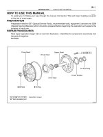
REPAIR PROCEDURES
Most repair operations begin with an overview illustration. It identifies the components and shows how
the parts fit together.
Example:
IN002–0W
INTRODUCTION HOW TO USE THIS MANUAL–
IN–2
The procedures are presented in a step–by–step format:
L The illustration shows what to do and where to do it.
L The task heading tells what to do.
L The detailed text tells how to perform the task and gives other information such as specifications
and warnings.
Example:
This format provides the experienced technician with a FAST TRACK to the information needed. The
upper case task heading can be read at a glance when necessary, and the text below it provides de-
tailed information. Important specifications and warnings always stand out in bold type.
REFERENCES
References have been kept to a minimum. However, when they are required you are given the page
to refer to.
SPECIFICATIONS
Specifications are presented in bold type throughout the text where needed. You never have to leave
the procedure to look up your specifications. They are also found at the back of AX section, for quick
reference.
INTRODUCTION HOW TO USE THIS MANUAL–
IN–3
CAUTIONS, NOTICES, HINTS:
L CAUTIONS are presented in bold type, and indicate there is a possibility of injury to you or other
people.
L NOTICES are also presented in bold type, and indicate the possibility of damage to the compo-
nents being repaired.
L HINTS are separated from the text but do not appear in bold. They provide additional information
to help you perform the repair efficiently.
SI UNIT
The UNITS given in this manual are primarily expressed according to the SI UNIT (International System
of Unit), and alternately expressed in the metric system and in the English system.
Example:
Torque: 30 N·m (310 kgf·cm, 22 ft·lbf)
INTRODUCTION GENERAL REPAIR INSTRUCTIONS–
IN–4
GENERAL REPAIR INSTRUCTIONS
1. Use fender, seat and floor covers to keep the vehicle
clean and prevent damage.
2. During disassembly, keep parts in the appropriate order
to facilitate reassembly.
3. Observe the following:
(a) Before performing electrical work, disconnect the
negative (–) terminal cable from the battery.
(b) If it is necessary to disconnect the battery for inspec-
tion or repair, always disconnect the cable from the
negative (–) terminal which is grounded to the ve-
hicle body.
(c) To prevent damage to the battery terminal post, loos-
en the terminal nut and raise the cable straight up
without twisting or prying it.
(d) Clean the battery terminal posts and cable terminals
with a clean shop rag. Do not scrape them with a file
or other abrasive objects.
(e) Install the cable terminal to the battery post with the
nut loose, and tighten the nut after installation. Do
not use a hammer to tap the terminal onto the post.
(f) Be sure the cover for the positive (+) terminal is prop-
erly in place.
4. Check hose and wiring connectors to make sure that they
are secure and correct.
5. Non–reusable parts
(a) Always replace cotter pins, gaskets, O–rings and oil
seals etc. with new ones.
(b) Non–reusable parts are indicated in the component
illustrations by the ”z” symbol.
6. Precoated parts
Precoated parts are bolts and nuts, etc. that are coated
with a seal lock adhesive at the factory.
(a) If a precoated part is retightened, loosened or
caused to move in any way, it must be recoated with
the specified adhesive.
(b) When reusing precoated parts, clean off the old
adhesive and dry with compressed air. Then apply
IN022–07
INTRODUCTION GENERAL REPAIR INSTRUCTIONS–
IN–5
the specified seal lock adhesive to the bolt, nut or
threads.
(c) Precoated parts are indicated in the component il-
lustrations by the ”L” symbol.
7. When necessary, use a sealer on gaskets to prevent
leaks.
8. Carefully observe all specifications for bolt tightening
torques. Always use a torque wrench.
9. Use of special service tools (SST) and special service ma-
terials (SSM) may be required, depending on the nature
of the repair. Be sure to use SST and SSM where speci-
fied and follow the proper work procedure. A list of SST
and SSM can be found at the preparation of AX section.
10. When replacing fuses, be sure the new fuse has the cor-
rect amperage rating. DO NOT exceed the rating or use
one with a lower rating.
11. To pull apart electrical connectors, pull on the connector
itself, not the wires.
12. Care must be taken when jacking up and supporting the
vehicle. Be sure to lift and support the vehicle at the prop-
er locations.
(a) If the vehicle is to be jacked up only at the front or
rear end, be sure to block the wheels at the opposite
end in order to ensure safety.
(b) After the vehicle is jacked up, be sure to support it on
stands. It is extremely dangerous to do any work on
a vehicle raised on a jack alone, even for a small job
that can be finished quickly.
INTRODUCTION GLOSSARY OF SAE AND TOYOTA TERMS–
IN–6
GLOSSARY OF SAE AND TOYOTA TERMS
This glossary lists all SAE–J1930 terms and abbreviations used in this manual in compliance with SAE
recommendations, as well as their Toyota equivalents.
SAE
ABBREVIATIONS
SAE TERMS
TOYOTA TERMS
( )––ABBREVIATIONS
A/C Air Conditioning Air Conditioner
ACL Air Cleaner Air Cleaner
AIR Secondary Air Injection Air Injection (AI)
AP Accelerator Pedal –
B+ Battery Positive Voltage +B, Battery Voltage
BARO Barometric Pressure –
CAC Charge Air Cooler Intercooler
CARB Carburetor Carburetor
CFI Continuous Fuel Injection –
CKP Crankshaft Position Crank Angle
CL Closed Loop Closed Loop
CMP Camshaft Position Cam Angle
CPP Clutch Pedal Position –
CTOX Continuous Trap Oxidizer –
CTP Closed Throttle Position –
DFI Direct Fuel Injection (Diesel) Direct Injection (DI)
DI Distributor Ignition –
DLC1
DLC2
DLC3
Data Link Connector 1
Data Link Connector 2
Data Link Connector 3
1: Check Connector
2: Toyota Diagnosis Communication Link (TDCL)
3: OBD@@@@@: [g 2] Diagnostic Connector
DTC Diagnostic Trouble Code Diagnostic Code
DTM Diagnostic Test Mode –
ECL Engine Control Level –
ECM Engine Control Module Engine ECU (Electronic Control Unit)
ECT Engine Coolant Temperature Coolant Temperature, Water Temperature (THW)
EEPROM
Electrically Erasable Programmable Read Only
Memory
Electrically Erasable Programmable Read Only Memory
(EEPROM),
Erasable Programmable Read Only Memory (EPROM)
EFE Early Fuel Evaporation Cold Mixture Heater (CMH), Heat Control Valve (HCV)
EGR Exhaust Gas Recirculation Exhaust Gas Recirculation (EGR)
EI Electronic Ignition Toyota Distributorless Ignition (TDI)
EM Engine Modification Engine Modification (EM)
EPROM Erasable Programmable Read Only Memory Programmable Read Only Memory (PROM)
EVAP Evaporative Emission Evaporative Emission Control (EVAP)
FC Fan Control –
FEEPROM
Flash Electrically Erasable Programmable
Read Only Memory
–
FEPROM Flash Erasable Programmable Read Only Memory –
FF Flexible Fuel –
FP Fuel Pump Fuel Pump
GEN Generator Alternator
GND Ground Ground (GND)
HO2S Heated Oxygen Sensor Heated Oxygen Sensor (HO2S)
IN016–02
INTRODUCTION GLOSSARY OF SAE AND TOYOTA TERMS–
IN–7
IAC Idle Air Control Idle Speed Control (ISC)
IAT Intake Air Temperature Intake or Inlet Air Temperature
ICM Ignition Control Module –
IFI Indirect Fuel Injection Indirect Injection
IFS Inertia Fuel–Shutoff –
ISC Idle Speed Control –
KS Knock Sensor Knock Sensor
MAF Mass Air Flow Air Flow Meter
MAP Manifold Absolute Pressure
Manifold Pressure
Intake Vacuum
MC Mixture Control
Electric Bleed Air Control Valve (EBCV)
Mixture Control Valve (MCV)
Electric Air Control Valve (EACV)
MDP Manifold Differential Pressure –
MFI Multiport Fuel Injection Electronic Fuel Injection (EFI)
MIL Malfunction Indicator Lamp Check Engine Light
MST Manifold Surface Temperature –
MVZ Manifold Vacuum Zone –
NVRAM Non–Volatile Random Access Memory –
O2S Oxygen Sensor Oxygen Sensor, O
2
Sensor (O
2
S)
OBD On–Board Diagnostic On–Board Diagnostic (OBD)
OC Oxidation Catalytic Converter Oxidation Catalyst Converter (OC), CCo
OP Open Loop Open Loop
PAIR Pulsed Secondary Air Injection Air Suction (AS)
PCM Powertrain Control Module –
PNP Park/Neutral Position –
PROM Programmable Read Only Memory –
PSP Power Steering Pressure –
PTOX Periodic Trap Oxidizer
Diesel Particulate Filter (DPF)
Diesel Particulate Trap (DPT)
RAM Random Access Memory Random Access Memory (RAM)
RM Relay Module –
ROM Read Only Memory Read Only Memory (ROM)
RPM Engine Speed Engine Speed
SC Supercharger Supercharger
SCB Supercharger Bypass –
SFI Sequential Multiport Fuel Injection Electronic Fuel Injection (EFI), Sequential Injection
SPL Smoke Puff Limiter –
SRI Service Reminder Indicator –
SRT System Readiness Test –
ST Scan Tool –
TB Throttle Body Throttle Body
TBI Throttle Body Fuel Injection
Single Point Injection
Central Fuel Injection (Ci)
TC Turbocharger Turbocharger
TCC Torque Converter Clutch Torque Converter
TCM Transmission Control Module Transmission ECU (Electronic Control Unit)
TP Throttle Position Throttle Position
TR Transmission Range –
INTRODUCTION GLOSSARY OF SAE AND TOYOTA TERMS–
IN–8
TVV Thermal Vacuum Valve
Bimetallic Vacuum Switching Valve (BVSV)
Thermostatic Vacuum Switching Valve (TVSV)
TWC Three–Way Catalytic Converter
Three–Way Catalyst (TWC)
CC
RO
TWC+OC Three–Way + Oxidation Catalytic Converter CC
R
+ CCo
VAF Volume Air Flow Air Flow Meter
VR Voltage Regulator Voltage Regulator
VSS Vehicle Speed Sensor Vehicle Speed Sensor (Read Switch Type)
WOT Wide Open Throttle Full Throttle
WU–OC Warm Up Oxidation Catalytic Converter –
WU–TWC Warm Up Three–Way Catalytic Converter Manifold Converter
3GR Third Gear –
4GR Fourth Gear –
INTRODUCTION ABBREVIATIONS USED IN THIS MANUAL–
IN–9
ABBREVIATIONS USED IN THIS
MANUAL
ATF Automatic Transaxle Fluid
B
0
Overdrive Brake
B
1
Second coast Brake
B
2
Second Brake
B
3
First and Reverse Brake
C
0
Overdrive Direct Clutch
C
1
Forward Clutch
C
2
Direct Clutch
D Disc
F Flange
F
0
O/D One–way Clutch
F
1
No.1 One–way Clutch
F
2
No.2 One–way Clutch
MP Multipurpose
O/D Overdirve
P Plate
SSM Special Service Materials
SST Special Service Tools
IN01H–0R
INTRODUCTION STANDARD BOLT TORQUE SPECIFICATIONS–
IN–10
STANDARD BOLT TORQUE SPECIFICATIONS
IN008–02
INTRODUCTION STANDARD BOLT TORQUE SPECIFICATIONS–
IN–11
AUTOMATIC TRANSAXLE SERVICE SPECIFICATIONS–
AX–12
SERVICE SPECIFICATIONS
SERVICE DATE
Oil Pump
Body clearance STD
0.07 – 0.15 mm
0.0028 – 0.0059 in.
Maximum
0.3 mm
0.012 in.
Tip clearance STD
0.11 – 0.14 mm
0.0043 – 0.0055 in.
Maximum
0.3 mm
0.012 in.
Side clearance STD
0.02 – 0.05 mm
0.0008 – 0.0020 in.
Maximum
0.1 mm
0.004 in.
Pump body bushing inside diameter Maximum
38.18 mm
1.5031 in.
Stator shaft bushing inside diameter
Front side
Maximum
21.57 mm
0.8492 in.
Rear side
Maximum
27.07 mm
1.0657 in.
Direct Clutch
Clutch drum bushing inside diameter Maximum
47.07 mm
1.8531 in.
Direct clutch piston stroke
1.11 – 1.44 mm
0.0437 – 0.0567 in.
Flange thickness
2.60 mm
0.1024 in.
3.00 mm
0.1181 in.
Forward Clutch
Piston stroke
1.41 – 1.82 mm
0.0555 – 0.0717 in.
Flange thickness
2.8 mm
0.110 in.
3.0 mm
0.118 in.
3.2 mm
0.126 in.
3.4 mm
0.134 in.
3.6 mm
0.142 in.
Front Planetary Gear
AT06P–0C
AUTOMATIC TRANSAXLE SERVICE SPECIFICATIONS–
AX–13
Ring gear bushing inside diameter Standard
19.025 – 19.050 mm
0.7490 – 0.7500 in.
Planetary pinion gear thrust clearance Standard
0.20 – 0.50 mm
0.0079 – 0.0197 in.
Rear Planetary Gear
Planetary pinion gear thrust clearance Standard
0.20 – 0.50 mm
0.0079 – 0.0197 in.
Overdrive Unit
Overdrive direct clutch piston stroke
1.21 – 1.91 mm
0.0476 – 0.0752 in.
Overdrive direct clutch bushing inside diameter Maximam
22.09 mm
0.8697 in.
Counter drive gear preload
9 – 15 N
920 – 1,530 gf 2.0 – 3.4 lbf
Planetary pinion gear thrust clearance Standard
0.20 – 0.50 mm
0.0079 – 0.0197 in.
AUTOMATIC TRANSAXLE SERVICE SPECIFICATIONS–
AX–14
Valve Body Spring
Spring
Free length and Coil outer
diameter mm (in.)
Total No. of coils and Color
Upper valve body
Throttle modulator valve
21.7 (0.854)
9.5 (0.374)
9.5
None
Accumulator control valve
28.1 (0.105)
10.6 (0.417)
13.0
Yellow
Low coast modulator valve
21.6 (0.850)
7.9 (0.311)
11.5
None
Down shift plug
29.8 (1.172)
8.7 (0.344)
13.5
Yellow
Throttle valve
30.7 (1.209)
9.2 (0.362)
9.5
None
Second coast modulator valve
20.9 (0.824)
8.5 (0.336)
10.0
Light Green
Cut–back valve
21.8 (0.858)
6.0 (0.236)
13.5
None
Lock–up relay valve
26.6 (1.046)
10.2 (0.402)
11.5
Green
Lower valve body
Pressure relief valve
11.2 (0.441)
6.4 (0.252)
7.5
None
1 – 2 shift valve
29.3 (1.152)
9.7 (0.382)
10.5
None
2 – 3 shift valve
29.3 (1.152)
9.7 (0.382)
10.5
None
3 – 4 shift valve
29.3 (1.152)
9.7 (0.382)
10.5
None
Primary regulator valve
66.7 (2.453)
18.6 (0.732)
12.5
None
Secondary regulator valve
43.6 (1.717)
10.9 (0.429)
11.5
None
Lock–up signal valve
30.0 (1.181)
8.2 (0.323)
11.5
None
Cooler By–pass valve
19.9 (0.784)
11.0 (0.433)
8.5
None
Valve Body Retainer
Reteiner
Height
mm (in.)
Width
mm (in.)
Thickness
mm (in.)
Upper valve body
Throttle Modulator valve 9.2 (0.362) 5.0 (0.197) 3.2 (0.126)
Accumulator control valve 11.5 (0.453) 5.0 (0.197) 3.2 (0.126)
Cut–back valve 9.2 (0.591) 5.0 (0.197) 3.2 (0.126)
Lock–up relay valve 15.0 (0.591) 5.0 (0.197) 3.2 (0.126)
Second coast modulator valve 15.0 (0.591) 5.0 (0.197) 3.2 (0.126)
Lower valve body
Primary regulator valve 9.2 (0.362) 5.0 (0.197) 3.2 (0.126)
AUTOMATIC TRANSAXLE SERVICE SPECIFICATIONS–
AX–15
1 – 2 shift valve 9.2 (0.362) 5.0 (0.197) 3.2 (0.126)
2 – 3 shift valve 8.0 (0.315) 5.0 (0.197) 3.2 (0.126)
3 – 4 shift valve 8.0 (0.315) 5.0 (0.197) 3.2 (0.126)
Lock–up signal valve 15.0 (0.591) 5.0 (0.197) 3.2 (0.126)
Accumulator Spring
Spring Free length mm (in.) Color
C
1
57.64 (2.2693) Red, Purple
B
2
69.39 (2.7323) Green, White
C
2
70.21 (2.7641) Purple
AUTOMATIC TRANSAXLE SERVICE SPECIFICATIONS–
AX–16
Differential
Drive pinion preload (at starting) New bearing
Reused bearing
1.0 – 1.6 N·m
10 – 16 kgf·cm 8.7 – 13.9 in.·lbf
0.5 – 0.8 N·m
5 – 8 kgf·cm 4.3 – 6.9 in.·lbf
Total preload (at starting)
New bearing
Reused bearing
Add drive pinion preload
0.3 – 0.4 N·m
2.9 – 4.0 kgf·cm 2.5 – 3.5 in.·lbf
0.1 – 0.2 N·m
1.5 – 2.0 kgf·cm 1.3 – 1.7 in.·lbf
Pinion to side gear backlash
0.05 – 0.20 mm
0.0020 – 0.0079 in.
Side gear thrust washer thickness
0.95 mm
0.0374 in.
1.00 mm
0.0394 in.
1.05 mm
0.0413 in.
1.10 mm
0.0433 in.
1.20 mm
0.0427 in.
AUTOMATIC TRANSAXLE SERVICE SPECIFICATIONS–
AX–17
Side bearing adjusting shim thickness
1.90 mm
0.0748 in.
1.95 mm
0.0768 in.
2.00 mm
0.0787 in.
2.05 mm
0.0807 in.
2.10 mm
0.0827 in.
2.15 mm
0.0846 in.
2.20 mm
0.0866 in.
2.25 mm
0.0886 in.
2.30 mm
0.0906 in.
2.35 mm
0.0925 in.
2.40 mm
0.0945 in.
2.45 mm
0.0965 in.
2.50 mm
0.0984 in.
2.55 mm
0.1004 in.
2.60 mm
0.1024 in.
2.65 mm
0.1043 in.
2.70 mm
0.1063 in.
2.75 mm
0.1083 in.
2.80 mm
0.1103 in.
AUTOMATIC TRANSAXLE SERVICE SPECIFICATIONS–
AX–18
TORQUE SPECIFICATION
Part tightened N·m kgf·cm ft·lbf
Stator shaft x Oil pump body 10 100 7
Upper valve body x Lower valve body 5.4 55 48 <in.lbf>
Ring gear x Differential case 97 985 71
Side bearing cap x Transaxle case 72 730 53
Bearing retainer x Transaxle case 19 195 14
Counter drive gear x Drive pinion 172 1,750 127
Carrier cover x Transaxle case 25 250 18
Parking lock pawl bracket 7.4 75 65 in.·lbf
Overdrive case x Transaxle case 25 260 19
Oil pump x Transaxle case 22 220 16
Valve body x Transaxle case 10 100 7
Manual valve body x Transaxle case 10 100 7
Detent spring x Valve body 10 100 7
Oil tube bracket x Transaxle case 10 100 7
Oil strainer x Valve body 10 100 7
Oil pan x Transaxle case 4.9 50 43 in.·lbf
Park/Neutral position switch 6.9 70 61 in.·lbf
Park/Neutral position switch adjusting bolt 5.4 55 48 in.·lbf
Union 27 275 20
AT06Q–0C
AUTOMATIC TRANSAXLE GENERAL DESCRIPTION–
AX–1
GENERAL DESCRIPTION
The A140E automatic transaxle described in this AX section is a 4–speed lock–up automatic transaxle
developed exclusively for use with a transversely–mounted engine.
AX0EP–02
AUTOMATIC TRANSAXLE GENERAL DESCRIPTION–
AX–2
General Specifications
Type of Transaxle A140E
Type of Engine 5S–FE
Torque Converter Clutch Stall Torque Ratio 2.0 : 1
Lock–up Mechanism Equipped
Gear Ratio 1st Gear
2nd Gear
3rd Gear
O/D Gear
Reverse Gear
2.810
1.549
1.000
0.706
2.296
Number of Discs and Plates O/D Direct Clutch (C
0
)
Forward Clutch (C
1
)
Direct Clutch (C
2
)
Second Brake (B
2
)
First and Reverse Brake (B
3
)
O/D Brake (B
0
)
2/1
4/4
3/3
3/3
6/5
2/3
B
1
Band Width mm (in.) 25 mm (0.98 in.)
ATF Type ATF DEXRON ® @@@@@: [g 2]
Capacity liter (US qts, Imp. qts)
Transaxle
Differential
5.6 (5.9, 4.9)
1.6 (1.7, 1.4)
AUTOMATIC TRANSAXLE OPERATION–
AX–3
OPERATION
OPERATION
AX0SW–01
AUTOMATIC TRANSAXLE OPERATION–
AX–4
1. FUNCTION OF COMPONENTS
FUNCTION OPERATION
O/D Direct Clutch (C
0
) Connects overdrive sun gear and overdrive carrier
O/D Brake (B
0
)
Prevents overdrive sun gear from turning either clockwise or
counterclockwise
O/D One–way Clutch (F
0
)
When transmission is being driven by engine, connects overdrive sun
gear and overdrive carrier.
Front Clutch (C
1
) Connects input shaft and intermediate shaft
Rear Clutch (C
2
) Connects input shaft and front and rear planetary sun gears
No.1 Brake (B
1
)
Prevents front and rear planetary sun gears from turning either clockwise
or counterclockwise
No.2 Brake (B
2
)
Prevents outer race of F
1
from turning either clockwise or counterclockwise, thus
previnting front and rear planetary sun gears from turning counterclockwise
No.3 Brake (B
3
) Prevents front planetary carrier from turning either clockwise or counterclockwise
No.1 One–way Clutch (F
1
)
When B
2
is operating prevents front and rear planetary sun gears from turning
counterclockwise
No.2 One–way Clutch (F
2
) Prevents front planetary carrier from turning counterclockwise
AUTOMATIC TRANSAXLE OPERATION–
AX–5
Power from the engine transmitted to the input shaft via the torque converter is then transmitted to the
planetary gears by the operation of the clutch.
By operation of the brake and one–way clutch, either the planetary carrier or the planetary sun gear
are immobilized, altering the speed of revolution of the planetary gear unit.
Shift change is carried out by altering the combination of clutch and brake operation.
Each clutch and brake operates by hydraulic pressure; gear position is decided according to the throttle
opening angle and vehicle speed, and shift change automatically occurs.
The conditions of operation for each gear position are shown on the following illustrations:
AUTOMATIC TRANSAXLE OPERATION–
AX–6
2. HYDRAULIC CONTROL SYSTEM
The hydraulic control system is composed of the oil pump, the valve body, the solenoid valves, the accu-
mulators, the clutches and brakes, and the governor valve as well as the fluid passages which connect
all of these components.
Based on the hydraulic pressure created by the oil pump, the hydraulic control system governs the hy-
draulic pressure acting on the torque converter clutch, clutches and brakes in accordance with the ve-
hicle driving conditions.
There are three solenoid valves on the valve body.
The No.1 and No.2 solenoid valves are turned on and off by signals from the ECM to operate the shift
valves and change the gear shift position.
The No.3 solenoid valve is operated by signals from the ECM to engage or disengage the lock–up
clutch of the torque converter.
AUTOMATIC TRANSAXLE OPERATION–
AX–7
2. ELECTRONIC CONTROL SYSTEM
The electronic control system for controlling the shift timing and the operation of the lock–up clutch is
composed of the following 3 parts:
(a) Sensors: These sense the vehicle speed and throttle position and send this data to the ECM in the form
of electronic signals.
(b) ECM: This determines the shift and lock–up timing based upon the signals from the sensors.
(c) Actuators: Solenoid valves divert hydraulic pressure from one circuit of the hydraulic control unit to
another, thus controlling shifting and lock–up timing.