Camry Repair Manual BODY ELECTRICAL BODY
Bạn đang xem bản rút gọn của tài liệu. Xem và tải ngay bản đầy đủ của tài liệu tại đây (3.6 MB, 298 trang )
BE09Y–01
–BODY ELECTRICAL BODY ELECTRICAL SYSTEM
BE–1
2221AuthorĂ: DateĂ:
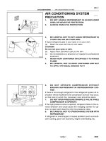
BODY ELECTRICAL SYSTEM
PRECAUTION
Take care to observe the following precautions when performing inspections or removal and replacement
of body electrical related parts.
1. HEADLIGHT SYSTEM
z Halogen bulbs have pressurized gas inside and require special handling. They can burst if scratched
or dropped. Hold a bulb only by its plastic or metal case. Don’t touch the glass part of a bulb with bare
hands.
2. SRS (SUPPLEMENTAL RESTRAINT SYSTEM)
z The CAMRY is equipped with an SRS (Supplemental Restraint System) such as the driver airbag and
front passenger airbag. Failure to carry out service operation in the correct sequence could cause the
SRS to unexpectedly deploy during servicing, possibly leading to a serious accident. Before servicing
(including removal or installation of parts, inspection or replacement), be sure to read the precaution-
ary notices in the RS section.
3. AUDIO SYSTEM
z If the negative (–) terminal cable is disconnected from the battery, the preset AM, FM 1 and FM 2 sta-
tions stored in memory are erased, so make sure to note the stations and reset them after the negative
(–) terminal cable is reconnected to the battery.
z If the negative (–) terminal cable is disconnected from the battery, the ”ANTI–THEFT SYSTEM” will
operate when the cable is reconnected, but the radio, tape player and CD player will not operate. Be
sure to input the correct ID number so that the radio, tape player and CD player can be operated again.
4. MOBILE COMMUNICATION SYSTEM
z If the vehicle is equipped with a mobile communication system, refer to precautions in the IN section.
BE09Z–03
BE–2
–BODY ELECTRICAL BODY ELECTRICAL SYSTEM
2222AuthorĂ: DateĂ:
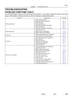
PROBLEM SYMPTOMS TABLE
POWER OUTLET
Symptom Suspect Area See page
Electric power source cannot be taken out of the power outlet
11.Battery
12.POWER OUTLET Fuse (I/P J/B No.1)
13.Wire Harness
–
–
–
HEADLIGHT AND TAILLIGHT SYSTEM (USA)
Symptom Suspect Area See page
Headlight does not light.
(Taillight is normal)
1. HEAD–(LH, RH) Fuse (E/G Room J/B No.2)
2. Headlight Bulb
3. Wire Harness
–
–
–
Headlight does not light.
(Taillight does not light up)
1. HEAD–(LH, RH) Fuse (E/G Room J/B No.2)
2. Headlight Control Relay (E/G Room J/B No.2)
3. Headlight Bulb
4. Wire Harness
–
BE–24
–
–
Only one side light does not light.
1. HEAD–(LH, RH) Fuse (E/G Room J/B No.2)
2. Headlight Bulb
3. Wire Harness
–
–
–
”Lo–Beam” does not light.
1. Headlight Bulb
2. Light Control Switch
3. Wire Harness
–
BE–24
–
”Hi–Beam” does not light.
1. Headlight Dimmer Switch
2. Light Control Switch
3. Wire Harness
BE–24
BE–24
–
”Flash” does not light.
1. Headlight Dimmer Switch
2. Wire Harness
BE–24
–
”Auto Turn–off System” does not operate.
1. GAUGE Fuse (I/P J/B No.1)
2. DOME Fuse (E/G Room J/B No.2)
3. Integration Relay (I/P J/B No.2)
4. Door Courtesy Switch (Driver’s)
5. Ignition Switch
6. Wire Harness
–
–
BE–14
BE–24
BE–14
–
Taillight does not light. (Headlight does not light)
1. Light Control Switch
2. Integration Relay (I/P J/B No.1)
3. Wire Harness
BE–24
BE–14
–
Taillight does not light.
(Headlight is normal)
1. TAIL Fuse (I/P J/B No.1)
2. Taillight Control Relay (I/P J/B No.1)
3. Light Control Switch
4. Integration Relay (I/P J/B No.1)
5. Wire Harness
–
BE–24
BE–24
BE–14
–
Only one side light does not light.
1. Bulb
2. Wire Harness
–
–
Rear Combination light does not light.
1. Bulb
2. Light Failure Sensor
3. Wire Harness
–
BE–37
–
”Auto Turn–off System” does not operate.
1. GAUGE Fuse (I/P J/B No.1)
2. Integration Relay (I/P J/B No.1)
3. Door Courtesy Switch (Driver’s)
4. Wire Harness
–
BE–14
BE–32
–
–BODY ELECTRICAL BODY ELECTRICAL SYSTEM
BE–3
2223AuthorĂ: DateĂ:
HEADLIGHT AND TAILLIGHT SYSTEM (CANADA)
Symptom Suspect Area See page
Headlight does not light.
(Taillight is normal)
1. Wire Harness –
Headlight does not light.
(Taillight does not light up)
1. Wire Harness –
Only one side light does not light.
1. Headlight Bulb
2. HEAD LO (LH, RH) Fuse (E/G Room R/B No.2)
3. Wire Harness
–
–
–
”Lo–Beam” does not light.
1. Headlight Bulb
2. HEAD LO (LH, RH) Fuse (E/G Room R/B No.2)
3. Headlight Control Relay (E/G Room J/B No.2)
4. Integration Relay (I/P J/B No.1)
5. Light Control Switch
6. Wire Harness
–
–
BE–24
BE–14
BE–24
–
”Hi–Beam” does not light.
1. Headlight Bulb
2. ECU–B Fuse (E/G Room J/B No.2)
3. HEAD HI (LH, RH) Fuse (E/G Room J/B No.2)
4. DRL Fuse (E/G Room R/B No.2)
5. Daytime Running Light Relay No.2
(E/G Room R/B No.2)
6. Daytime Running Light Relay No.3
(E/G Room R/B No.2)
7. Daytime Running Light Relay No.4
(E/G Room R/B No.2)
8. Daytime Running Light Relay (Main)
9. Headlight Dimmer Switch
10.Wire Harness
–
–
–
–
–
BE–24
–
BE–24
–
BE–24
BE–24
BE–24
–
”Flash” does not light.
1. Headlight Bulb
2. ECU–B Fuse (E/G Room J/B No.2)
3. HEAD HI (LH, RH) Fuse (E/G Room J/B No.2)
4. DRL Fuse (E/G Room R/B No.2)
5. Daytime Running Light Relay No.2
(E/G Room R/B No.2)
6. Daytime Running Light Relay No.3
(E/G Room R/B No.2)
7. Daytime Running Light Relay No.4
(E/G Room R/B No.2)
8. Daytime Running Light Relay (Main)
9. Headlight Dimmer Switch
10.Wire Harness
–
–
–
–
–
BE–24
–
BE–24
–
BE–24
BE–24
BE–24
–
”Auto Turn–off System” does not operate.
1. GAUGE Fuse (I/P J/B No.1)
2. DOME Fuse (E/G Room J/B No.2)
3. Integration Relay (I/P J/B No.2)
4. Door Courtesy Switch (Driver’s)
5. Ignition Switch
6. Wire Harness
–
–
BE–14
BE–24
BE–14
–
Headlight does not light with engine running and light control SW
OFF.
1. Headlight Bulb
2. ECU–B Fuse (E/G Room J/B No.2)
3. GAUGE Fuse (I/P J/B No.1)
4. HEAD HI (LH, RH) Fuse (E/G Room J/B No.2)
5. Daytime Running Light Relay (Main)
6. Wire Harness
7. Other Parts*
–
–
–
–
BE–24
–
–
BE–4
–BODY ELECTRICAL BODY ELECTRICAL SYSTEM
2224AuthorĂ: DateĂ:
Taillight does not light.
(Headlight does not light)
1. Integration Relay (I/P J/B No.1)
2. Light Control Switch
3. Wire Harness
BE–14
BE–24
–
Taillight does not light.
(Headlight is normal)
1. TAIL Fuse (I/P J/B No.1)
2. Taillight Control Relay (I/P J/B No.1)
3. Integration Relay (I/P J/B No.1)
4. Light Control Switch
5. Wire Harness
–
BE–24
BE–14
BE–24
–
Only one side light does not light.
1. Bulb
2. Wire Harness
–
–
Rear Combination light does not light.
1. Bulb
2. Light Failure Sensor
3. Wire Harness
–
BE–37
–
”Auto Turn–off System” does not operate.
1. GAUGE Fuse (I/P J/B No.1)
2. Integration Relay (I/P J/B No.1)
3. Door Courtesy Switch (Driver’s)
4. Wire Harness
–
BE–14
BE–24
–
*Terminal L of generator and parking brake switch
TURN SIGNAL AND HAZARD WARNING SYSTEM
Symptom Suspect Area See page
”Hazard” and ”Turn” do not light up.
1. Hazard Warning Switch
2. Turn Signal Flasher
3. Wire Harness
BE–30
BE–30
–
The flashing frequency is abnormal.
1. Bulb
2. Turn Signal Switch
3. Wire Harness
–
BE–30
–
Hazard warning light does not light up.
(Turn is normal.)
1. HORN Fuse (E/G Room J/B No.2)
2. Wire Harness
–
–
Hazard warning light does not light up in one direction.
1. Hazard Warning Switch
2. Wire Harness
BE–30
–
*
1
Turn signal does not light up.
1. Ignition Switch
2. TURN Fuse (I/P J/B No.1)
3. Turn Signal Switch
4. Wire Harness
BE–14
–
BE–30
–
*
2
Turn signal does not light up.
1. TURN Fuse (I/P J/B No.1)
2. Turn Signal Switch
3. Wire Harness
–
BE–30
–
Turn signal does not light up in one direction.
1. Turn Signal Switch
2. Wire Harness
BE–30
–
Only one bulb does not light up.
1. Bulb
2. Wire Harness
–
–
*
1
: Combination meter, wiper and washer do not operate.
*
2
: Combination meter, wiper and washer are normal.
INTERIOR LIGHT SYSTEM
Symptom Suspect Area See page
”Illuminated Entry System” does not operate.
1. Door Courtesy Switch
2. Integration Relay (I/P J/B No.1)
3. Wire Harness
BE–32
BE–14
–
Only one interior light does not light up.
1. Bulb
2. Wire Harness
–
–
Interior light does not light up (All).
1. DOME Fuse (E/G Room J/B No.2)
2. Wire Harness
–
–
–BODY ELECTRICAL BODY ELECTRICAL SYSTEM
BE–5
2225AuthorĂ: DateĂ:
Dome light does not light up.
1. Bulb
2. Dome Light
3. Wire Harness
–
BE–32
–
Map Light does not light up.
1. Bulb
2. Map Light
3. Wire Harness
–
BE–32
–
Luggage compartment light does not light up.
1. Bulb
2. Luggage compartment door courtesy switch
3. Wire Harness
–
BE–32
–
BACK–UP LIGHT SYSTEM
Symptom Suspect Area See page
Back–Up Light does not light up.
1. GAUGE Fuse (I/P J/B No.1)
2. Ignition Switch
3. Wire Harness
4. Bulb
–
BE–14
–
–
Back–Up Light remains always ON.
1. Back–Up Light Switch (M/T)
2. Park/Neutral Position Switch (A/T) (A140E)
(A541E)
3. Wire Harness
BE–35
DI–424
DI–479
–
Only one light does not light up.
1. Bulb
2. Wire Harness
–
–
STOP LIGHT SYSTEM
Symptom Suspect Area See page
Stop light does not light up.
1. STOP Fuse (I/P J/B No.1)
2. Stop Light Switch
3. Wire Harness
–
BE–37
–
Only one light always lights up. 1. Wire Harness –
Only one light does not light.
1. Bulb
2. Wire Harness
–
–
WIPER AND WASHER SYSTEM
*
1
: Inspect wiper arm and blade set position
Symptom Suspect Area See page
Wiper and washers do not operate.
1. WIPER Fuse (I/P J/B No.1)
2. Wiper Switch
3. Wiper Motor
4. Wire Harness
–
BE–40
BE–40
–
Wipers do not operate in LO or HI.
1. Wiper Switch
2. Wiper Motor
3. Wire Harness
BE–40
BE–40
–
Wipers do not operate in INT.
1. Wiper Switch
2. Wiper Motor
3. Wire Harness
BE–40
BE–40
–
Washer motor does not operate.
1. Washer Switch
2. Washer Motor
3. Wire Harness
BE–40
BE–40
–
Wipers do not operate when washer switch in ON.
1. Washer Motor
2. Wire Harness
BE–40
–
BE–6
–BODY ELECTRICAL BODY ELECTRICAL SYSTEM
2226AuthorĂ: DateĂ:
Washer fluid does not operate. 1. Washer Hose and Nozzle –
z In wiper switch HI position, the wiper blade is in contact with
the body.
z When the wiper switch is OFF, the wiper blade does not
retract or the retract position is wrong.
1. *
1
Wiper Switch
2. Wire Harness
BE–40
–
COMBINATION METER
METER, GAUGES AND ILLUMINATION:
Symptom Suspect Area See page
Tachometer, Fuel Gauge and Engine Coolant Temperature Gauge
do not operate.
1. GAUGE Fuse (I/P J/B No.1)
2. Meter Circuit Plate
3. Wire Harness
–
BE–46
–
Speedometer does not operate.
1. No.1 Vehicle Speed Sensor
2. Meter Circuit Plate
3. Wire Harness
BE–47
BE–46
–
Tachometer does not operate.
1. Igniter (5S–FE)
(1MZ–FE)
2. Meter Circuit Plate
3. Wire Harness
IG–1
IG–1
BE–46
–
Fuel Gauge does not operate or abnormal operation.
1. Fuel Receiver Gauge
2. Fuel Sender Gauge
3. Meter Circuit Plate
4. Wire Harness
BE–47
BE–47
BE–46
–
Engine Coolant Temperature Gauge does not operate or abnormal
operation
1. Engine Coolant Temperature Receiver Gauge
2. Engine Coolant Temperature Sender Gauge
3. Meter Circuit Plate
4. Wire Harness
BE–47
BE–47
BE–46
–
All illumination lights do not light up.
1. TAIL Fuse (I/P J/B No.1)
2. Light Control Rheostat
3. Wire Harness
–
BE–47
–
Brightness does not change even when rheostat turned.
1. Bulb
2. Wire Harness
–
–
Only one illumination light does not light up.
1. Bulb
2. Wire Harness
–
–
COMBINATION METER
WARNING LIGHTS:
Symptom Suspect Area See page
Warning lights do not light up. (Except Discharge, Open Door and
SRS)
1. GAUGE Fuse (I/P J/B No.1)
2. Meter Circuit Plate
3. Wire Harness
–
BE–46
–
Low Oil Pressure warning light does not light up.
1. Bulb
2. Low Oil Pressure Warning Switch
3. Meter Circuit Plate
4. Wire Harness
–
BE–47
BE–46
–
Fuel Level warning light does not light up.
1. Bulb
2. Fuel Level Warning Switch
3. Meter Circuit Plate
4. Wire Harness
–
BE–47
BE–46
–
ABS warning light does not light up.
1. Bulb
2. ABS ECU
3. Wire Harness
–
IN–31
–
–BODY ELECTRICAL BODY ELECTRICAL SYSTEM
BE–7
2227AuthorĂ: DateĂ:
Seat Belt warning light does not light up.
1. Bulb
2. Seat Belt Buckle Switch
3. Integration Relay (I/P J/B No.1)
4. Wire Harness
–
BE–47
BE–47
–
Discharge warning light does not light up.
1. IGN Fuse (I/P J/B No.1)
2. Bulb
3. Wire Harness
4. Generator (5S–FE)
(1MZ–FE)
–
–
–
CH–1
CH–1
Light Failure warning light does not light up.
1. Bulb
2. Light Failure Sensor
3. Bulb Check Relay
4. Wire Harness
5. Taillight system
–
BE–37
BE–47
–
BE–24
Brake warning light does not light up.
1. Bulb
2. Parking Brake Switch
3. Brake Fluid Level Warning Switch
4. Bulb Check Relay
5. Meter Circuit Plate
6. Wire Harness
–
BE–47
BE–47
BE–47
BE–46
–
SRS Warning light does not light up.
1. ECU–B Fuse (E/G Room J/B No.2)
2. Bulb
3. Airbag Sensor Assembly
4. Meter Circuit Plate
5. Wire Harness
–
–
DI–626
BE–46
–
Open Door warning light does not light up.
1. DOME Fuse (E/G Room J/B No.2)
2. Bulb
3. Door Courtesy Switch
4. Meter Circuit Plate
5. Wire Harness
–
–
BE–32
BE–46
–
Washer Level warning light does not light up.
1. Bulb
2. Washer Fluid Level Warning Switch
3. Meter Circuit Plate
4. Wire Harness
–
BE–47
BE–46
–
COMBINATION METER
INDICATOR LIGHTS:
Symptom Suspect Area See page
O/D OFF indicator light does not light up.
1. Bulb
2. O/D OFF Switch (A140E)
(A541E)
3. Meter Circuit Plate
4. Wire Harness
–
DI–431
DI–487
BE–46
–
Cruise Control indicator light does not light up.
1. Bulb
2. Cruise Control ECU
3. Meter Circuit Plate
4. Wire Harness
–
IN–31
BE–46
–
High beam indicator light does not light up.
1. Bulb
2. Meter Circuit Plate
3. Wire Harness
4. Headlight System
–
BE–46
–
BE–22
Turn indicator light does not light up.
1. Bulb
2. Meter Circuit Plate
3. Wire Harness
4. Turn Signal and Hazard Warning System
–
BE–46
–
BE–29
BE–8
–BODY ELECTRICAL BODY ELECTRICAL SYSTEM
2228AuthorĂ: DateĂ:
Shift indicator lights do not light up.
1. Bulb
2. Meter Circuit Plate
3. Park/Neutral Position Switch (A140E)
(A541E)
4. Wire Harness
–
BE–46
DI–424
DI–479
–
Only one shift indicator does not light up.
1. Bulb
2. Meter Circuit Plate
–
BE–46
Malfunction indicator light does not light up.
1. Bulb
2. ECM
3. Meter Circuit Plate
4. Wire Harness
–
–
BE–46
–
SLIP indicator light does not light up.
1. Bulb
2. Traction ECU
3. Meter Circuit Plate
4. Wire Harness
–
–
BE–46
–
TRAC OFF indicator light does not light up.
1. Bulb
2. Traction ECU
3. Meter Circuit Plate
4. Wire Harness
–
–
BE–46
–
Security indicator light does not light up.
1. Bulb
2. Security ECU
3. Meter Circuit Plate
4. Wire Harness
–
–
BE–46
–
Indicator lights do not light up. (Except Turn, Hi–beam and
security)
1. GAUGE Fuse (I/P J/B No.1)
2. Wire Harness
–
–
DEFOGGER SYSTEM
Symptom Suspect Area See page
All defogger systems do not operate.
1. DEFOG M–Fuse (I/P J/B No.1)
2. HTR Fuse (I/P J/B No.1)
3. Defogger Relay (I/P J/B No.1)
4. Defogger Switch
5. Wire Harness
–
–
BE–56
BE–56
–
Rear window defogger does not operate.
1. Defogger Wire
2. Choke Coil
3. Wire Harness
BE–56
–
–
Mirror defogger does not operate.
1. MIR/HTR Fuse (I/P J/B No.1)
2. Mirror Defogger
3. Wire Harness
–
BE–56
–
POWER WINDOW CONTROL SYSTEM
Symptom Suspect Area See page
Power window does not operate (ALL).
(Power Door Lock does not operate)
1. POWER M–Fuse (I/P J/B No.1)
2. Power Main Relay (I/P J/B No.1)
3. Wire Harness
–
BE–60
–
Power window does not operate (ALL).
(Power Door Lock is normal)
1. Ignition Switch
2. Power Window Master Switch
3. Wire Harness
BE–14
BE–60
–
”One Touch Power Window System” does not operate. 1. Power Window Master Switch BE–60
Only one window glass does not move.
1. Power Window Master Switch
2. Power Window Switch
3. Power Window Motor
4. Wire Harness
BE–60
BE–60
BE–60
–
”Window Lock System” does not operate. 1. Power Window Master Switch BE–60
–BODY ELECTRICAL BODY ELECTRICAL SYSTEM
BE–9
2229AuthorĂ: DateĂ:
”Window Lock Illumination” does not light up. 1. Power Window Master Switch BE–60
Key–off power window does not operate.
1. GAUGE Fuse (I/P J/B No.1)
2. Integration Relay (I/P J/B No.1)
3. Ignition Switch
4. Door Courtesy Switch
5. Wire Harness
–
BE–60
BE–14
BE–32
–
POWER DOOR LOCK CONTROL SYSTEM
Symptom Suspect Area See page
”Door lock system” does not operate at all.
1. POWER M–Fuse (I/P J/B No.1)
2. CIG Fuse (I/P J/B No.1)
3. DOOR Fuse (I/P J/B No.1)
4. Integration Relay (I/P J/B No.1)
5. Wire Harness
–
–
–
BE–70
–
Door lock system does not operate by manual switch.
1. Power Window Master Switch
2. Door Lock Manual Switch
3. Integration Relay (I/P J/B No.1)
4. Wire Harness
BE–60
BE–70
BE–70
–
Door lock system does not operate by door key.
1. Door Key Lock and Unlock Switch
2. Integration Relay (I/P J/B No.1)
3. Wire Harness
4. Door Lock Link Disconnected
BE–70
BE–70
–
–
Fault in 2–Operation unlock function of Driver’s side door key lock
and unlock switch.
1. Door Key Lock and Unlock Switch
2. Integration Relay (I/P J/B No.1)
3. Wire Harness
BE–70
BE–70
–
Fault in key confine prevention operate.
1. Integration Relay (I/P J/B No.1)
2. Key Unlock Warning Switch
3. Door Courtesy Switch
4. Wire Harness
BE–70
BE–14
BE–32
–
Only one door lock does not operate.
1. Door Lock Motor
2. Wire Harness
BE–70
–
SLIDING ROOF SYSTEM
Symptom Suspect Area See page
Sliding roof system does not operate.
(Door Lock does not operate)
1. POWER M–Fuse (I/P J/B No.1)
2. Power Main Relay (I/P J/B No.1)
3. Wire Harness
–
BE–60
–
Sliding roof system does not operate.
(Door Lock is normal)
1. Ignition Switch
2. Sliding Roof Control Relay and Switch
3. Sliding Roof Motor and Limit Switch
4. Wire Harness
BE–14
BE–74
BE–74
–
Sliding roof system operates abnormally.
1. Sliding Roof Control Relay and Switch
2. Sliding Roof Motor and Limit Switch
3. Wire Harness
BE–74
BE–74
–
Sliding roof system stops operation half way.
(Stones of foreign material trapped in motor assembly)
1. Sliding Roof Control Relay and Switch
2. Sliding Roof Motor and Limit Switch
3. Wire Harness
BE–74
BE–74
–
”Key–off Sliding Roof” operation does not operate.
1. DOME Fuse (E/G Room J/B No.2)
2. GAUGE Fuse (I/P J/B No.1)
3. Ignition Switch
4. Integration Relay (I/P J/B No.1)
5. Wire Harness
–
–
BE–14
BE–14
–
BE–10
–BODY ELECTRICAL BODY ELECTRICAL SYSTEM
2230AuthorĂ: DateĂ:
POWER SEAT CONTROL SYSTEM
Symptom Suspect Area See page
Power seat does not operate.
(Door lock system does not operate)
1. POWER M–Fuse (I/P J/B No.1)
2. Wire Harness
–
–
Power seat does not operate.
(Door lock system is normal)
1. Power Seat Swtich (D,P)
2. Wire Harness
BE–78
–
”Slide operation” does not operate.
1. Power Seat Switch (D, P)
2. Wire Harness
3. Slide Motor (D, P)
BE–78
–
BE–78
”Lifter Operation” does not operate.
1. Power Seat Switch (D, P)
2. Wire Harness
3. Lifter Motor (D, P)
BE–78
–
BE–78
”Reclining Operation” does not operate.
1. Power Seat Switch (D, P)
2. Wire Harness
3. Reclining Motor (D, P)
BE–78
–
BE–78
(D): Driver’s seat
(P): Passenger’s seat
POWER MIRROR CONTROL SYSTEM
Symptom Suspect Area See page
Mirror does not operate.
1. CIG Fuse (I/P J/B No.1)
2. Mirror Switch
3. Mirror Motor
4. Wire Harness
–
BE–83
BE–83
–
Mirror operates abnormally.
1. Mirror Switch
2. Mirror Motor
3. Wire Harness
BE–83
BE–83
–
BE0A0–03
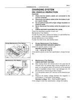
Z19043
Engine Room Relay Block No.1
Engine Room Junction
Block No.2
Engine Room Relay Block No.2
Instrument Panel Junction Block No.1
Turn Signal Flasher
–BODY ELECTRICAL POWER SOURCE
BE–11
2231AuthorĂ: DateĂ:
POWER SOURCE
LOCATION
BE0A1–03
N20688
Power Outlet
Instrument Panel J/B No.1
z PWR OUTLET Fuse
BE–12
–BODY ELECTRICAL POWER OUTLET
2232AuthorĂ: DateĂ:
POWER OUTLET
LOCATION
BE0A2–03
N20687
Key Unlock Warning Switch
Instrument Panel J/B No.1
z Integration Relay
Ignition Switch
–BODY ELECTRICAL IGNITION SWITCH AND KEY UNLOCK WARNING
SWITCH
BE–13
2233AuthorĂ: DateĂ:
IGNITION SWITCH AND KEY UNLOCK WARNING SWITCH
LOCATION
BE0A3–02
N14824
LOCK
ACC
ON
1
34
5768
START
2
N20125
OFF
ON
1
2
N20126
10
1
6
5
N20127
10
1
6
5
BE–14
–BODY ELECTRICAL IGNITION SWITCH AND KEY UNLOCK WARNING
SWITCH
2234AuthorĂ: DateĂ:
INSPECTION
1. INSPECT IGNITION SWITCH CONTINUITY
Switch position Tester connection Specified condition
LOCK – No continuity
ACC 2 – 3 Continuity
ON
2 – 3 – 4
6 – 7
Continuity
START
1 – 2 – 4
6 – 7 – 8
Continuity
If continuity is not as specified, replace the switch.
2. INSPECT KEY UNLOCK WARNING SWITCH CONTI-
NUITY
Switch position Tester connection Specified condition
OFF (Key removed) – No continuity
ON (Key set) 1 – 2 Continuity
If continuity is not as specified, replace the switch.
3. Key unlock warning system:
INSPECT INTEGRATION RELAY (TYPE A) OPERA-
TION
(a) Connect the positive (+) lead from the battery to terminal
1.
(b) Connect the negative (–) lead from the battery to termi-
nals 5, 6 and 10.
(c) Check the buzzer sounds.
(d) Disconnect the negative (–) lead from the battery to termi-
nal 6.
(e) Check that the buzzerr stops sounding.
N20128
10
1
6
5
N20129
10
1
6
5
N20130
10
1
65
N20131
10
1
65
N20132
10
1
6
5
–BODY ELECTRICAL IGNITION SWITCH AND KEY UNLOCK WARNING
SWITCH
BE–15
2235AuthorĂ: DateĂ:
(f) Connect the negative (–) lead from the battery to terminal
6.
(g) Disconnect the negative (–) lead from the battery to termi-
nal 5.
(h) Check that the buzzerr stops sounding.
If operation is not as specified, replace the relay.
4. Key unlock warning system:
INSPECT INTEGRATION RELAY (TYPE B) OPERA-
TION
(a) Connect the positive (+) lead from the battery to terminal
1.
(b) Connect the negative (–) lead from the battery to termi-
nals 5, 6 and 10.
(c) Check the buzzerr sounds.
(d) Disconnect the negative (–) lead from the battery to termi-
nal 6.
(e) Check that the buzzerr stops sounding.
(f) Connect the negative (–) lead from the battery to terminal
6.
(g) Disconnect the negative (–) lead from the battery to termi-
nal 5.
(h) Check that the buzzerr stops sounding.
If operation is not as specified, replace the relay.
5. Key unlock warning system:
INSPECT INTEGRATION RELAY (TYPE C) OPERA-
TION
(a) Connect the positive (+) lead from the battery to terminal
1.
(b) Connect the negative (–) lead from the battery to termi-
nals 5, 6 and 10.
(c) Check the buzzerr sounds.
N20133
10
1
6
5
N20134
10
1
6
5
N20135
Junction block side:
123456781011 912
BE–16
–BODY ELECTRICAL IGNITION SWITCH AND KEY UNLOCK WARNING
SWITCH
2236AuthorĂ: DateĂ:
(d) Disconnect the negative (–) lead from the battery to termi-
nal 6.
(e) Check that the buzzerr stops sounding.
(f) Connect the negative (–) lead from the battery to terminal
6.
(g) Disconnect the negative (–) lead from the battery to termi-
nal 5.
(h) Check that the buzzerr stops sounding.
If operation is not as specified, replace the relay.
6. INSPECT INTEGRATION RELAY (TYPE A) CIRCUIT
(a) Remove the relay from the junction block No.1 and in-
spect the connector on the junction block side.
Tester connection Condition Specified condition
2 – Ground
4 – Ground
Passenger’s door courtesy switch OFF (Door
closed)
No continuity
2 – Ground
4 – Ground
Passenger’s door courtesy switch ON (Door
opened)
Continuity
5 – Ground Key unlock warning switch OFF No continuity
5 – Ground Key unlock warning switch ON Continuity
6 – Ground Driver’s door courtesy switch OFF No continuity
6 – Ground Driver’s door courtesy switch ON Continuity
8 – Ground Buckle switch OFF (Seat belt unfastened) No continuity
8 – Ground Buckle switch ON (Seat belt fastened) Continuity
10 – Ground Constant Continuity
1 – Ground Constant Battery positive voltage
7 – Ground
9 – Ground
Ignition switch LOCK or ACC No voltage
7 – Ground
9 – Ground
Ignition switch ON Battery positive voltage
N20136
Wire harness side:
1234
N20135
Junction block side:
12345678
1011
9
12
–BODY ELECTRICAL IGNITION SWITCH AND KEY UNLOCK WARNING
SWITCH
BE–17
2237AuthorĂ: DateĂ:
(b) Disconnect the connector from the integration relay and
inspect the connector on the wire harness side.
Tester connection Condition Specified condition
1 – Ground Light control switch OFF No continuity
1 – Ground Light control switch HEAD or TAIL Continuity
4 – Ground Light control switch OFF or TAIL No continuity
4 – Ground Light control switch HEAD Continuity
2 – Ground
3 – Ground
Constant Battery positive voltage
If the circuit is as specified, try replacing the relay with a new
one.
If the circuit is not as specified, inspect the circuits connected
to other parts.
7. INSPECT INTEGRATION RELAY (TYPE B) CIRCUIT
(a) Remove the relay from the junction block No.1 and in-
spect the connector on the junction block side.
Tester connection Condition Specified condition
2 – Ground
All door courtesy switches OFF (Except Driver’s
Door/ Door closed)
No continuity
2 – Ground
One of the door courtesy switches ON (Except
Driver’s Door/ Door opened)
Continuity
4 – Ground
Door courtesy switches except that of the driver’s
door OFF (Door closed)
No continuity
4 – Ground
One of the door courtesy switches except that of
the driver’s door ON (Door opened)
Continuity
N20137
Wire harness side:
Wire harness side:
20141312
11108479
22211918171516
56123
23 24 25
1234
Connector ”A”
Connector ”B”
eh–25–1
h–4–1
BE–18
–BODY ELECTRICAL IGNITION SWITCH AND KEY UNLOCK WARNING
SWITCH
2238AuthorĂ: DateĂ:
5 – Ground Key unlock warning switch OFF No continuity
5 – Ground Key unlock warning switch ON Continuity
6 – Ground Driver’s door courtesy switch OFF (Door closed) No continuity
6 – Ground Driver’s door courtesy switch ON (Door opened) Continuity
8 – Ground Buckle switch OFF (Seat belt unfastened) No continuity
8 – Ground Buckle switch ON (Seat belt fastened) Continuity
10 – Ground Constant Continuity
1 – Ground Constant Battery positive voltage
7 – Ground
9 – Ground
Ignition switch LOCK or ACC No voltage
7 – Ground
9 – Ground
Ignition switch ON Battery positive voltage
11 – Ground Ignition switch LOCK No voltage
11 – Ground Ignition switch ACC or ON Battery positive voltage
(b) Disconnect the connector from the integration relay and
inspect the connectors on the wire harness side.
Tester connection Condition Specified condition
A3 – Ground Constant Continuity
A5 – Ground
Driver’s door unlock detection switch OFF (Door
locked)
No continuity
A5 – Ground
Driver’s door unlock detection switch ON (Door
unlocked)
Continuity
A6 – Ground
Passenger’s door courtesy switch OFF (Door
closed)
No continuity
N20135
Junction block side:
12345678
1011
9
12
–BODY ELECTRICAL IGNITION SWITCH AND KEY UNLOCK WARNING
SWITCH
BE–19
2239AuthorĂ: DateĂ:
A6 – Ground
Passenger’s door courtesy switch ON (Door
opened)
Continuity
A7 – Ground
Passenger’s door unlock detection switch OFF
(Door locked)
No continuity
A7 – Ground
Passenger’s door unlock detection switch ON
(Door unlocked)
Continuity
A9 – Ground
Rear door unlock detection switch OFF (Door
locked)
No continuity
A9 – Ground
Rear door unlock detection switch ON (Door
unlocked)
Continuity
A11 – A12
A12 – A25
Constant Continuity
A16 – Ground Door lock manual switch OFF or UNLOCK No continuity
A16 – Ground Door lock manual switch LOCK Continuity
A17 – Ground Door lock manual switch OFF or LOCK No continuity
A17 – Ground Door lock manual switch UNLOCK Continuity
A18 – Ground
Driver’s and passenger’s door key lock and
unlock switch OFF or UNLOCK
No continuity
A18 – Ground
Driver’s or passenger’s door key lock and unlock
switch LOCK
Continuity
A19 – Ground
Driver’s door key lock and unlock switch OFF or
LOCK
No continuity
A19 – Ground
Driver’s door key lock and unlock switch
UNLOCK
Continuity
A20 – Ground
Passenger’s door key lock and unlock switch
OFF or LOCK
No continuity
A20 – Ground
Passenger’s door key lock and unlock switch
UNLOCK
Continuity
A1 – Ground Constant Battery positive voltage
B1 – Ground Light control switch OFF No voltage
B1 – Ground Light control switch TAIL or HEAD Battery positive voltage
B4 – Ground Light control switch OFF or TAIL No voltage
B4 – Ground Light control switch HEAD Battery positive voltage
B2 – Ground
B3 – Ground
Constant Battery positive voltage
If the circuit is as specified, try replacing the relay with a new
one.
If the circuit is not as specified, inspect the circuits connected
to other parts.
8. INSPECT INTEGRATION RELAY (TYPE C) CIRCUIT
(a) Remove the relay from the junction block No.1 and in-
spect the connector on the junction block side.
N20138
Wire harness side:
Wire harness side:
131211108
4
79
5
6
123
1234
Connector ”A”
Connector ”B”
BE–20
–BODY ELECTRICAL IGNITION SWITCH AND KEY UNLOCK WARNING
SWITCH
2240AuthorĂ: DateĂ:
Tester connection Condition Specified condition
2 – Ground
All door courtesy switches OFF (Except Driver’s
Door/ Door closed)
No continuity
2 – Ground
One of the door courtesy switches ON (Except
Driver’s Door/ Door opened)
Continuity
4 – Ground
Door courtesy switches except that of the driver’s
door OFF (Door closed)
No continuity
4 – Ground
One of the door courtesy switches except that of
the driver’s door ON (Door opened)
Continuity
5 – Ground Key unlock warning switch OFF No continuity
5 – Ground Key unlock warning switch ON Continuity
6 – Ground Driver’s door courtesy switch OFF (Door closed) No continuity
6 – Ground Driver’s door courtesy switch ON (Door opened) Continuity
8 – Ground Buckle switch OFF (Seat belt unfastened) No continuity
8 – Ground Buckle switch ON (Seat belt fastened) Continuity
10 – Ground Constant Continuity
1 – Ground Constant Battery positive voltage
7 – Ground
9 – Ground
Ignition switch LOCK or ACC No voltage
7 – Ground
9 – Ground
Ignition switch ON Battery positive voltage
11 – Ground Ignition switch LOCK No voltage
11 – Ground Ignition switch ACC or ON Battery positive voltage
(b) Disconnect the connector from the integration relay and
inspect the connectors on the wire harness side.
–BODY ELECTRICAL IGNITION SWITCH AND KEY UNLOCK WARNING
SWITCH
BE–21
2241AuthorĂ: DateĂ:
Tester connection Condition Specified condition
A1 – Ground Door lock manual switch OFF or UNLOCK No continuity
A1 – Ground Door lock manual switch LOCK Continuity
A2 – Ground Door lock manual switch OFF or LOCK No continuity
A2 – Ground Door lock manual switch UNLOCK Continuity
A3 – Ground
Driver’s and passenger’s door key lock and
unlock switch OFF or UNLOCK
No continuity
A3 – Ground
Driver’s or passenger’s door key lock and unlock
switch LOCK
Continuity
A4 – Ground
Driver’s door key lock and unlock switch OFF or
LOCK
No continuity
A4 – Ground
Driver’s door key lock and unlock switch
UNLOCK
Continuity
A5 – Ground
Passenger’s door key lock and unlock switch
OFF or LOCK
No continuity
A5 – Ground
Passenger’s door key lock and unlock switch
UNLOCK
Continuity
A6 – A7 Constant Continuity
A8 – Ground
Passenger’s door courtesy switch OFF (Door
closed)
No continuity
A8 – Ground
Passenger’s door courtesy switch ON (Door
opened)
Continuity
A9 – Ground
Driver’s door unlock detection switch OFF (Door
closed)
No continuity
A9 – Ground
Driver’s door unlock detection switch ON (Door
opened)
Continuity
A10 – Ground
Passenger’s door unlock detection switch OFF
(Door closed)
No continuity
A10 – Ground
Passenger’s door unlock detection switch ON
(Door opened)
Continuity
A11 – Ground
Rear door unlock detection switch OFF (Door
closed)
No continuity
A11 – Ground
Rear door unlock detection switch ON (Door
opened)
Continuity
A12 – Ground Constant Continuity
A13 – Ground Constant Battery positive voltage
B1 – Ground Light control switch OFF No voltage
B1 – Ground Light control switch TAIL or HEAD Battery positive voltage
B4 – Ground Light control switch OFF or TAIL No voltage
B4 – Ground Light control switch HEAD Battery positive voltage
B2 – Ground
B3 – Ground
Constant Battery positive voltage
If the circuit is as specified, try replacing the relay with a new
one.
If the circuit is not as specified, inspect the circuits connected
to other parts.
BE0A4–02
I08436
Daytime Resister
E/G Room J/B No.2
z HEAD LH Fuse (USA)
z HEAD RH Fuse (USA)
z HEAD LH (UPR) Fuse (CANADA)
z HEAD RH (UPR) Fuse (CANADA)
z DOME Fuse
z ECU–B Fuse
z Headlight Control Relay
E/G Room R/B No.2 (CANADA)
z HEAD LH (LWR) Fuse
z HEAD RH (LWR) Fuse
z DRL No.2 Fuse
z Daytime Running Light Relay No.4
Headlight
Instrument Panel J/B No.1
z GAUGE Fuse
z TAIL Fuse
z Taillight Control Relay
z Integration Relay
Daytime Running
Light Relay
Ignition Switch
Combination Switch
z Light Control Switch
z Headlight Dimmer Switch
Door Courtesy Switch
Light Failure Sensor
Taillight
Automatic Light
Control Sensor
BE–22
–BODY ELECTRICAL HEADLIGHT AND TAILLIGHT SYSTEM
2242AuthorĂ: DateĂ:
HEADLIGHT AND TAILLIGHT SYSTEM
LOCATION
BE0A5–02
N18012
Combination Switch
z Light Control Switch
z Headlight Dimmer Switch
Switch Body
Combination Switch
z Wiper and Washer Switch
Spiral Cable
–BODY ELECTRICAL HEADLIGHT AND TAILLIGHT SYSTEM
BE–23
2243AuthorĂ: DateĂ:
COMPONENTS
BE10D–01
N20149
HEAD
Hi beam
TAIL
OFF
Flash
87
17 16
14
13
Z08521
1
2
3
4
12
4
3
N14863
1
2
3
5
1
2
35
Z08523
1
2
3
4
12
4
3
BE–24
–BODY ELECTRICAL HEADLIGHT AND TAILLIGHT SYSTEM
2244AuthorĂ: DateĂ:
INSPECTION
1. INSPECT LIGHT CONTROL SWITCH CONTINUITY
Switch position Tester connection Specified condition
OFF – No continuity
TAIL 14 – 16 Continuity
HEAD 13 – 14 – 16 Continuity
If continuity is not as specified, replace the switch.
2. INSPECT HEADLIGHT DIMMER SWITCH CONTINU-
ITY
Switch position Tester connection Specified condition
Low beam 16 – 17 Continuity
High beam 7 – 16 Continuity
Flash 7 – 8 – 16 Continuity
If continuity is not as specified, replace the switch.
3. INSPECT HEADLIGHT CONTROL RELAY CONTINU-
ITY
Condition Tester connection Specified condition
Constant 1 – 2 Continuity
Apply B+ between
terminals 1 and 2.
3 – 4 Continuity
If continuity is not as specified, replace the relay.
4. INSPECT TAILLIGHT CONTROL RELAY CONTINUITY
Condition Tester connection Specified condition
Constant 1 – 2 Continuity
Apply B+ between
terminals 1 and 2.
3 – 5 Continuity
If continuity is not as specified, replace the relay.
5. INSPECT HEADLIGHT DIMMER RELAY CONTINUITY
Condition Tester connection Specified condition
Constant 1 – 4, 2 – 4 Continuity
Apply B+ between
terminals 2 and 4.
3 – 4 Continuity
If continuity is not as specified, replace the relay.
I08219
Wire harness side:
–BODY ELECTRICAL HEADLIGHT AND TAILLIGHT SYSTEM
BE–25
2245AuthorĂ: DateĂ:
6. INSPECT DAYTIME RUNNING LIGHT RELAY (MAIN)
CIRCUIT
Disconnect the connector from the relay and inspect the con-
nector on the wire harness side.
Tester connection Condition Specified condition
2 – Ground Light control switch position OFF or TAIL No continuity
2 – Ground Light control switch position HEAD Continuity
3 – Ground
Headlight dimmer switch position
Low beam
No continuity
3 – Ground
Headlight dimmer switch position
High beam of Flash
Continuity
4 – Ground Brake fluid level warning position OFF No continuity
4 – Ground Brake fluid level warning position ON Continuity
12 – Ground Constant Continuity
14 – Ground
Parking brake switch position OFF
(Parking brake lever released)
No continuity
14 – Ground
Parking brake switch position ON
(Parking brake lever pulled up)
Continuity
17 – Ground Light control switch position OFF or HEAD No voltage
17 – Ground Light control switch position TAIL Continuity
20 – Ground Constant Continuity
21 – Ground Constant Continuity
13 – Ground Engine Stop No voltage
13 – Ground Engine Running Battery positive voltage
16 – Ground Constant Battery positive voltage
18 – Ground Ground terminal 19 Battery positive voltage
19 – Ground Constant Battery positive voltage
22 – Ground Constant Battery positive voltage
23 – Ground Ignition switch position LOCK or ACC No voltage
23 – Ground Ignition switch position ON or START Battery positive voltage
If circuit is as specified, try replacing the relay with a new one.
If circuit is not as specified, inspect the circuits connected to oth-
er parts.