Camry Repair Manual MANUAL TRANSAXLE
Bạn đang xem bản rút gọn của tài liệu. Xem và tải ngay bản đầy đủ của tài liệu tại đây (1.47 MB, 92 trang )
MX04X–01
–MANUAL TRANSAXLE (E153) MANUAL TRANSAXLE SYSTEM
MX–1
1802A uthorĂ: DateĂ:
MANUAL TRANSAXLE SYSTEM
PRECAUTION
When working with FIPG material, you must observe the following items.
L Using a razor blade and gasket scraper, remove all the old FIPG material from the gasket sur-
faces.
L Thoroughly clean all components to remove all the loose material.
L Clean both sealing surfaces with a non–residue solvent.
L Apply FIPG in an approx. 1 mm (0.04 in.) wide bead along the sealing surface.
L Parts must be assembled within 10 minutes of application. Otherwise, the FIPG material must
be removed and reapplied.
MX04Y–01
MX–2
–MANUAL TRANSAXLE (E153) TROUBLESHOOTING
1803A uthorĂ: DateĂ:
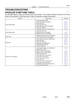
TROUBLESHOOTING
PROBLEM SYMPTOMS TABLE
Use the table below to help you find the cause of the problem. The numbers indicate the priority of the likely
cause of the problem. Check each part in order. If necessary, replace parts.
Symptom Suspect Area See page
1. Oil (Level low)
MX
–
4
Ni
1
.
Oil
(Level
low)
2. Oil
(
Wron
g)
MX
–
4
MX–4
Noise
2
.
Oil
(Wrong)
3. Gear (Worn or damaged)
MX–4
MX–10
3.
Gear
(Worn
or
damaged)
4. Bearing (Worn or damaged)
MX 10
MX–10
1. Oil (Level too high)
MX
–
4
Oil l k
1
.
Oil
(Level
too
high)
2. Gasket
(
Dama
g
ed
)
MX
–
4
MX–10
Oil leakage
2
.
Gasket
(Damaged)
3. Oil seal (Worn or damaged)
MX–10
MX–10
3.
Oil
seal
(Worn
or
damaged)
4. O–Ring (Worn or damaged)
MX 10
MX–10
1. Control cable (Faulty)
2. Synchronizer ring (Worn or damaged)
MX–49
MX–10
Hard to shift or will not shift
yg( g)
3 Shift key s
p
ring (Damaged)
MX–24
MX–31
MX
–
10
3
.
Shift
k
ey spr
i
ng
(D
amage
d)
MX
–
10
MX–24
MX–31
1. Locking ball s
p
ring (Damaged)
MX
–
10
Jtf
1
.
Locking
ball
spring
(Damaged)
2. Shift fork
(
Worn
)
MX
–
10
MX–10
Jumps out of gear
2
.
Shift
fork
(Worn)
3. Gear (Worn or damaged)
MX–10
MX–10
3.
Gear
(Worn
or
damaged)
4. Bearing (Worn or damaged)
MX 10
MX–10
MX04Z–01
Q09981
Hood
14 (150, 10)
w/ Cruise Control :
Cruise Control Actuator
12 (120, 9)
Clutch Line Bracket
21 (210, 15)
12 (120, 9)
Clutch Release Cylinder
26 (270, 20)
RH Drive Shaft
L
L
32 (330, 24)
7.8 (80, 69 in.·lbf)
Flywheel Housing Under Cover
RH Fender
Apron Seal
Clutch Accumulator
Vehicle Speed Sensor
Connector
46 (470, 34)
Engine LH Mounting
Insulator with Bracket
Rear RH Suspension Member Brace
37 (380, 27)
Transaxle
64 (650, 47)
36 (370, 27)
10 (100, 7)
Steering Return Pipe
19 (195, 14)
32 (330, 24)
181 (1,850, 134)
Silver Bolt : 44 (450, 33)
Green Bolt : 66 (670, 48)
Suspension Member with
Lower Suspension Arm
Front RH Suspension
Member Brace
181 (1,850, 134)
Control
Cable
Clip
13 (130, 9)
Clip
Washer
Starter
21 (210, 15)
39 (400, 29)
Air Cleaner
Case Assembly
with Air Hose
64 (650, 47)
Ground Cable
x5
Back–Up Light Switch Connector
Engine Wire
20 (200, 14)
Hold–Down
Clamp
Battery
LH Drive Shaft
LH Fender Apron Seal
RH Exhaust Manifold Stay
64 (650, 47)
181 (1,850, 134) PS Gear Assembly
No.1 Fuel Tube Protector
49 (500, 36)
294 (3,000, 217)
Lock Cap
Rear LH Suspension Member Brace
Stabilizer Bar Link
Hole
Plug
127 (1,300, 94)
39 (400, 29)
80 (820, 59)
48 (490, 35)
Silver Bolt : 44 (450, 33)
Green Bolt : 66 (670, 48)
Front LH Suspension
Member Brace
RH Fender
Liner
Engine Rear Side
Shutter Plate
56 (570, 41)
L
L
62 (630, 46)
L
62 (630, 46)
L
Front Exhaust Pipe
No.1 Exhaust Pipe
Support Bracket
33 (330, 24)
Exhaust Pipe Support Stay
33 (330, 24)
LH Fender
Liner
66 (670, 48)
Snap Ring
L
Snap Ring
LCotter Pin
L
Cotter Pin
LGasket
L Gasket
L
Gasket
Non–reusable part
: Specified torqueN·m (kgf·cm, ft·lbf)
L
36 (370, 27)
–MANUAL TRANSAXLE (E153) MANUAL TRANSAXLE UNIT
MX–3
1804A uthorĂ: DateĂ:
MANUAL TRANSAXLE UNIT
COMPONENTS
MX050–01
Q09982
Q09983
Q09984
Q09985
MX–4
–MANUAL TRANSAXLE (E153) MANUAL TRANSAXLE UNIT
1805A uthorĂ: DateĂ:
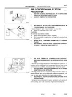
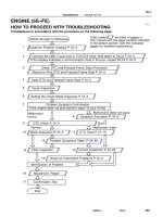
REMOVAL
1. REMOVE HOOD
HINT:
At the time of installation, please refer to the following item.
Adjust the hood.
(See page BO–10)
2. REMOVE BATTERY AND AIR CLEANER CASE AS-
SEMBLY WITH AIR HOSE
3. w/ Cruise Control:
REMOVE CRUISE CONTROL ACTUATOR
(a) Disconnect the cruise control actuator connector.
(b) Remove the 3 bolts and cruise control actuator with the
bracket.
Torque: 13 N·m (130 kgf·cm, 9 ft·lbf)
4. REMOVE STARTER
(a) Disconnect the connector and wire from the starter.
(b) Remove the 2 bolts and starter.
Torque: 39 N·m (400 kgf·cm, 29 ft·lbf)
5. DISCONNECT CLUTCH RELEASE CYLINDER
(a) Remove the 2 bolts and disconnect the release cylinder.
Torque: 12 N·m (120 kgf·cm, 9 ft·lbf)
(b) Remove the 2 set bolts and nut of the clutch accumulator.
Torque:
Bolt: 21 N·m (210 kgf·cm, 15 ft·lbf)
Nut: 26 N·m (270 kgf·cm, 20 ft·lbf)
(c) Remove the set bolt of the clutch line bracket.
Torque: 12 N·m (120 kgf·cm, 9 ft·lbf)
6. DISCONNECT GROUND CABLE
Remove the set bolt of the ground cable from the transaxle.
7. DISCONNECT ENGINE WIRE FROM CLAMP
8. DISCONNECT VEHICLE SPEED SENSOR AND
BACK–UP LIGHT SWITCH CONNECTORS
9. DISCONNECT CONTROL CABLE
(a) Remove the 2 clips and washers.
(b) Remove the 2 clips from the cables.
Q09986
Q09987
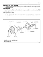
Filler Plug
Oil Level
0 – 5 mm
Drain Plug
Q09988
–MANUAL TRANSAXLE (E153) MANUAL TRANSAXLE UNIT
MX–5
1806A uthorĂ: DateĂ:
10. REMOVE 5 TRANSAXLE UPPER SIDE MOUNTING
BOLTS
Torque:
17 mm head: 64 N·m (650 kgf·cm, 47 ft·lbf)
11. REMOVE FRONT WHEEL
Torque: 103 N·m (1,050 kgf·cm, 76 ft·lbf)
12. RAISE VEHICLE
NOTICE:
Make sure that the vehicle is securely supported.
13. REMOVE ENGINE REAR SIDE SHUTTER PLATE AND
LH AND RH FENDER APRON SEALS
14. DRAIN TRANSAXLE OIL
Oil grade: API GL–4 or GL–5
Viscosity: SAE 75W–90
Capacity: 4.2 liters (4.4 US qts, 3.7 Imp. qts)
Torque: 49 N·m (500 kgf·cm, 36 ft·lbf)
15. REMOVE LH AND RH DRIVE SHAFTS
(See page SA–25)
16. REMOVE FRONT EXHAUST PIPE
(a) Remove the 2 bolts and exhaust pipe support stay.
Torque: 33 N·m (330 kgf·cm, 24 ft·lbf)
(b) Remove the 4 nuts and 2 gaskets from the exhaust man-
ifold.
Torque: 62 N·m (630 kgf·cm, 46 ft·lbf)
(c) Remove the 2 bolts, nuts and gasket.
Torque: 56 N·m (570 kgf·cm, 41 ft·lbf)
(d) Remove the 2 set bolts of the No.1 exhaust pipe support
bracket.
Torque: 33 N·m (330 kgf·cm, 24 ft·lbf)
(e) Remove the front exhaust pipe.
Q09989
Q09990
Q09991
Q09992
Q09993
MX–6
–MANUAL TRANSAXLE (E153) MANUAL TRANSAXLE UNIT
1807A uthorĂ: DateĂ:
17. DISCONNECT PS GEAR ASSEMBLY FROM FRONT
SUSPENSION MEMBER
(a) Remove the 2 nuts and disconnect the stabilizer bar link
from the stabilizer bar.
Torque: 39 N·m (400 kgf·cm, 29 ft·lbf)
(b) Remove the 4 set bolts of the stabilizer bar bracket.
Torque: 19 N·m (195 kgf·cm, 14 ft·lbf)
(c) Remove the 2 bolts, nut and No.1 fuel tube protector.
(d) Tie the PS gear assembly to the proper position with a
code or an equivalent to suspend the assembly securely.
(e) Remove the 2 set bolts and nuts of the PS gear assembly.
Torque: 181 N·m (1,850 kgf·cm, 134 ft·lbf)
18. DISCONNECT FRONT ENGINE ABSORBER FROM
TRANSAXLE
Remove the 2 bolts.
Torque: 48 N·m (490 kgf·cm, 35 ft·lbf)
19. REMOVE RH EXHAUST MANIFOLD STAY
Remove the bolt, nut and stay.
Torque: 20 N·m (200 kgf·cm, 14 ft·lbf)
20. REMOVE 3 ENGINE FRONT SIDE MOUNTING BOLTS
Torque:
Silver bolt: 44 N·m (450 kgf·cm, 33 ft·lbf)
Green bolt: 66 N·m (670 kgf·cm, 48 ft·lbf)
Q09994
Q09995
Q09996
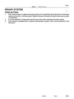
C
A
C
A
C
B
A
A B
C
Q09997
14 mm Head B
14 mm Head B
14 mm Head A
–MANUAL TRANSAXLE (E153) MANUAL TRANSAXLE UNIT
MX–7
1808A uthorĂ: DateĂ:
21. REMOVE LH ENGINE MOUNTING INSULATOR WITH
BRACKET
(a) Remove the 2 hole plugs, nuts and 3 bolts.
Torque:
Bolt: 64 N·m (650 kgf·cm, 47 ft·lbf)
Nut: 80 N·m (820 kgf·cm, 59 ft·lbf)
(b) Lift up the transaxle and remove the left engine mounting
insulator with the bracket.
22. REMOVE HOLE PLUG AND 4 ENGINE REAR SIDE
MOUNTING NUTS
Torque: 66 N·m (670 kgf·cm, 48 ft·lbf)
23. ATTACH ENGINE SLING DEVICE TO ENGINE HANG-
ER
(See page EM–69)
24. DISCONNECT STEERING RETURN PIPE FROM
FRONT SUSPENSION MEMBER
Remove the 2 bolts.
Torque: 10 N·m (100 kgf·cm, 7 ft·lbf)
25. REMOVE FRONT SUSPENSION MEMBER WITH LOW-
ER SUSPENSION ARM
(a) Remove the LH and RH fender liner set screws.
(b) Remove the 6 bolts, 4 nuts, front LH and RH suspension
member braces, rear LH and RH suspension member
braces and front suspension member with the lower sus-
pension arm.
Torque:
Bolt A: 181 N·m (1,850 kgf·cm, 134 ft·lbf)
Bolt B: 32 N·m (330 kgf·cm, 24 ft·lbf)
Nut C: 36 N·m (370 kgf·cm, 27 ft·lbf)
26. JACK UP TRANSAXLE SLIGHTLY
Using a transmission jack, support the transaxle.
27. REMOVE FLYWHEEL HOUSING UNDER COVER AND
TRANSAXLE LOWER SIDE MOUNTING BOLT
(a) Remove the 2 bolts and cover.
Torque: 7.8 N·m (80 kgf·cm, 69 in.·lbf)
(b) Remove the 3 bolts of the transaxle lower side.
Torque:
14 mm head A: 46 N·m (470 kgf·cm, 34 ft·lbf)
14 mm head B: 37 N·m (380 kgf·cm, 27 ft·lbf)
MX–8
–MANUAL TRANSAXLE (E153) MANUAL TRANSAXLE UNIT
1809A uthorĂ: DateĂ:
28. REMOVE TRANSAXLE
Lower the engine left side and remove the transaxle from the
engine.
HINT:
At the time of installation, please refer to the following items.
L Align the input shaft with the clutch disc and install the
transaxle to the engine.
L Temporarily tighten the transaxle mounting bolts.
MX051–01
–MANUAL TRANSAXLE (E153) MANUAL TRANSAXLE UNIT
MX–9
1810A uthorĂ: DateĂ:
INSTALLATION
Installation is in the reverse order of removal (See page MX–4).
HINT:
After installation, check and inspect items as follows.
L Front wheel alignment (See page SA–4).
L Do the road test.
MX052–02
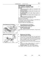
Z19124
Clutch Release Fork Assembly
with Bearing
Clutch Release Fork Support
Control Level Housing
Support Bracket
Boot
O–ring
Vehicle Speed Sensor
Transaxle Case Receiver
Clutch Release
Line Bracket
Cover
Transaxle Case
Transmission Oil
Pipe
Transmission
Oil Cooler
Sub–Assembly
Elbow O–ring
Magnet
Transmission Oil Pump
Assembly
Differential Case Assembly
Oil Pump Drive Gear
Output Shaft Cover
Tapered Roller Bearing
Outer Race
Front Oil Seal
Input Shaft Front
Bearing
N·m (kgf·cm, ft·lbf)
: Specified torque
Non–reusable part
47 (480, 35)
17 (175, 13)
17 (175, 13)
17 (175, 13)
17 (175, 13)
17 (175, 13)
7.4 (75, 65 in.·lbf)
17 (175, 13)
27 (275, 20)
34 (350, 25)
17 (175, 13)
Transmission Oil Pipe
MX–10
–MANUAL TRANSAXLE (E153) MANUAL TRANSAXLE ASSEMBLY
1811A uthorĂ: DateĂ:
MANUAL TRANSAXLE ASSEMBLY
COMPONENTS
Q10278
Reverse Shift Arm Bracket Assembly
Snap Ring
Reverse Shift Fork
No.1 Shift Fork
Straight Screw Plug
Seat
Spring
Ball
No.1 Shift Fork Shaft
Snap Ring
L
24 (240, 17)
25 (250, 18)
25 (250, 18)
L
Interlock Roller
No.2 Shift Fork Shaft
Snap Ring
Shift Head
25 (250, 18)
L
No.3 Shift Fork Shaft
Snap Ring
No.3 Shift Fork
24 (240, 17)
24 (240, 17)
No.2 Shift Fork
Back–Up Light Switch
40 (410, 30)
Straight Screw Plug
13 (130, 9)
Slotted Spring
Pin
Reverse Restrict
Pin
No.2 Oil Receiver Pipe
Shift and Select Lever
Shaft Lock Bolt
Breather Plug
49 (500, 36)
20 (200, 14)
29 (300, 22)
L
L
L
L
20 (200, 14)
x 17
Shift and Select Lever
Shaft Assembly
No.2 Selecting Bellcrank with
Selecting Bellcrank Support
29 (300, 22)
x 10
Transmission Case Cover
Drain Plug
49 (500, 36)
Transmission Case
Filler Plug
49 (500, 36)
No.1 Oil Receiver Pipe
17 (175, 13)
N·m (kgf·cm, ft·lbf) : Specified torque
Non–reusable part
LPrecoated part
Gasket
Gasket
Gasket
Gasket
Gasket
L
L 49 (500, 36)
Gasket
17 (175, 13)
–MANUAL TRANSAXLE (E153) MANUAL TRANSAXLE ASSEMBLY
MX–11
1812A uthorĂ: DateĂ:
Z17555
Input Shaft Assembly
Output Shaft Assembly
Tapered Roller Bearing
Outer Race
Shim
Thrust Washer
Reverse Idler Gear
Reverse Idler Gear Shaft
Lock Bolt
29 (300, 22)
L
42 (430, 31)
Rear Bearing Retainer
Snap Ring
Spacer
Needle Roller Bearing
5th Gear
5th Driven Gear
Key Spring
Inner Synchronizer Ring
Synchronizer Pull Ring
Key Spring
Outer Synchronizer Ring
Middle Synchronizer Ring
Snap Ring
Snap Ring
Output Shaft Lock Nut
123 (1,250, 90)
No.3 Clutch Hub
No.3 Hub Sleeve
N·m (kgf·cm, ft·lbf) : Specified torque
Non–reusable part
LPrecoated part
L
x 7
MX–12
–MANUAL TRANSAXLE (E153) MANUAL TRANSAXLE ASSEMBLY
1813A uthorĂ: DateĂ:
MX053–02
Q05816
FIPG
Q00449
–MANUAL TRANSAXLE (E153) MANUAL TRANSAXLE ASSEMBLY
MX–13
1814A uthorĂ: DateĂ:
DISASSEMBLY
1. REMOVE RELEASE FORK AND BEARING
2. REMOVE BACK–UP LIGHT SWITCH WITH GASKET
Torque: 40 N·m (410 kgf·cm, 30 ft·lbf)
3. REMOVE BOLT AND VEHICLE SPEED SENSOR
Torque: 17 N·m (175 kgf·cm, 13 ft·lbf)
4. REMOVE NO.2 SELECTING BELLCRANK WITH SE-
LECTING BELLCRANK SUPPORT
Remove the 2 bolts and No.2 selecting bellcrank with the se-
lecting bellcrank support.
Sealant:
Part No. 08833 – 00080, THREE BOND 1344, LOCTITE
242 or equivalent
Torque: 20 N·m (200 kgf·cm, 14 ft·lbf)
5. REMOVE SHIFT AND SELECT LEVER SHAFT LOCK
BOLT WITH GASKET
Torque: 49 N·m (500 kgf·cm, 36 ft·lbf)
6. REMOVE SHIFT AND SELECT LEVER SHAFT AS-
SEMBLY WITH GASKET
Remove the 4 bolts, shift and select lever shaft assembly and
gasket.
Sealant:
Part No. 08833 – 00080, THREE BOND 1344, LOCTITE
242 or equivalent
Torque: 20 N·m (200 kgf·cm, 14 ft·lbf)
7. REMOVE TRANSMISSION CASE COVER
Remove the 10 bolts and transmission case cover.
FIPG:
Part No. 08826 – 00090, THREE BOND 1281 or equiva-
lent
Torque: 29 N·m (300 kgf·cm, 22 ft·lbf)
8. REMOVE BREATHER PLUG WITH GASKET
Torque: 49 N·m (500 kgf·cm, 36 ft·lbf)
9. REMOVE OUTPUT SHAFT LOCK NUT
(a) Unstake the lock nut.
(b) Engage the gear double meshing.
(c) Remove the lock nut.
Torque: 123 N·m (1,250 kgf·cm, 90 ft·lbf)
(d) Disengage the gear double meshing.
10. REMOVE NO.3 HUB SLEEVE AND NO.3 SHIFT FORK
(a) Remove the No.3 shift fork set bolt.
Torque: 24 N·m (240 kgf·cm, 17 ft·lbf)
(b) Remove the No.3 hub sleeve and No.3 shift fork.
Q05849
SST
Z01304
Z01306
Q00299
MX–14
–MANUAL TRANSAXLE (E153) MANUAL TRANSAXLE ASSEMBLY
1815A uthorĂ: DateĂ:
11. REMOVE 5TH DRIVEN GEAR
Using SST, remove the 5th driven gear.
SST 09950–30010
12. MEASURE 5TH GEAR THRUST CLEARANCE AND
RADIAL CLEARANCE
(a) Using a dial indicator, measure the thrust clearance.
Standard clearance:
0.10 – 0.57 mm (0.0039 – 0.0224 in.)
Maximum clearance:
0.65 mm (0.0256 in.)
(b) Using a dial indicator, measure the radial clearance.
Standard clearance:
0.009 – 0.050 mm (0.0004 – 0.0020 in.)
Maximum clearance:
0.070 mm (0.0028 in.)
13. REMOVE NO.3 CLUTCH HUB AND 5TH GEAR
(a) Using 2 screwdrivers and a hammer, tap out the snap
ring.
HINT:
At the time of reassembly, please refer to the following item.
Select a snap ring that allows the minimum axial play.
Mark Thickness mm (in.) Mark Thickness mm (in.)
a 1.75 (0.0689) f 2.00 (0.0787)
b 1.80 (0.0709) g 2.05 (0.0807)
c 1.85 (0.0729) h 2.10 (0.0827)
d 1.90 (0.0748) j 2.15 (0.0847)
e 1.95 (0.0768) – –
Z01308
SST
Q06190
Q01615
Q00056
–MANUAL TRANSAXLE (E153) MANUAL TRANSAXLE ASSEMBLY
MX–15
1816A uthorĂ: DateĂ:
(b) Using SST, remove the No.3 clutch hub with the synchro-
nizer ring and 5th gear.
SST 09950–30010
14. REMOVE NEEDLE ROLLER BEARING AND SPACER
15. REMOVE REAR BEARING RETAINER
Using a torx socket wrench (T45), remove the 7 torx screws and
rear bearing retainer.
Sealant:
Part No. 08833 – 00080, THREE BOND 1344, LOCTITE
242 or equivalent
Torque: 42 N·m (430 kgf·cm, 31 ft·lbf)
16. REMOVE SNAP RING
(a) Using a snap ring expander, remove the input shaft rear
bearing snap ring.
(b) Using 2 screwdrivers and a hammer, remove the 2 snap
rings.
17. REMOVE STRAIGHT SCREW PLUG, SEAT, SPRING
AND LOCKING BALL
(a) Using a hexagon wrench (6 mm), remove the plug.
Sealant:
Part No. 08833 – 00080, THREE BOND 1344, LOCTITE
242 or equivalent
Torque: 25 N·m (250 kgf·cm, 18 ft·lbf)
(b) Using a magnetic finger, remove the seat, spring and
locking ball.
18. REMOVE REVERSE IDLER GEAR SHAFT LOCK BOLT
Sealant:
Part No. 08833 – 00080, THREE BOND 1344, LOCTITE
242 or equivalent
Torque: 29 N·m (300 kgf·cm, 22 ft·lbf)
Q05815
FIPG
MT0669
MT0693
SST
Q06375
Z17557
Matchmarks
MX–16
–MANUAL TRANSAXLE (E153) MANUAL TRANSAXLE ASSEMBLY
1817A uthorĂ: DateĂ:
19. REMOVE TRANSMISSION CASE
Remove the 17 bolts and tap the case with a plastic hammer.
FIPG:
Part No. 08826 – 00090, THREE BOND 1281 or equiva-
lent
Torque: 29 N·m (300 kgf·cm, 22 ft·lbf)
20. REMOVE SHIM
HINT:
At the time of reassembly, please refer to the following item.
Install the previously selected shim by adjusting output shaft
preload.
(See page MX–22)
21. REMOVE OUTPUT SHAFT REAR TAPER ROLLER
BEARING OUTER RACE
Using SST and a hammer, remove the output shaft rear taper
roller bearing outer race.
SST 09316–60011 (09316–00011)
22. REMOVE TRANSMISSION OIL PIPE
(a) Remove the gasket from the oil pipe.
(b) Remove the 2 bolts and oil pipe.
Torque: 17 N·m (175 kgf·cm, 13 ft·lbf)
23. REMOVE REVERSE SHIFT ARM BRACKET AS-
SEMBLY
Remove the bolt and pull off the reverse shift arm and bracket.
Torque: 17 N·m (175 kgf·cm, 13 ft·lbf)
24. REMOVE REVERSE IDLER GEAR AND SHAFT
Pull out the shaft, and remove the reverse idler gear and thrust
washer.
HINT:
At the time of reassembly, please refer to the following item.
Align the matchmarks, as shown.
Q01614
Q08124
Q08125
Q08126
Z00182
–MANUAL TRANSAXLE (E153) MANUAL TRANSAXLE ASSEMBLY
MX–17
1818A uthorĂ: DateĂ:
25. REMOVE STRAIGHT SCREW PLUG, LOCKING BALL
AND SPRING
(a) Using a hexagon wrench (6 mm), remove the 2 plugs.
Sealant:
Part No. 08833 – 00080, THREE BOND 1344, LOCTITE
242 or equivalent
Torque: 25 N·m (250 kgf·cm, 18 ft·lbf)
(b) Using a magnetic finger, remove the 2 seats, springs and
balls.
26. REMOVE NO.1, NO.2 SHIFT FORKS AND SHIFT HEAD
SET BOLT
Torque: 24 N·m (240 kgf·cm, 17 ft·lbf)
27. REMOVE NO.1 SHIFT FORK SHAFT
Pull up the No.3 shift fork shaft, and remove the No.1 shift fork
shaft.
HINT:
At the time of reassembly, please refer to the following item.
When it is difficult to push the fork shaft through the reverse shift
fork, pull up the No.3 shift fork shaft.
28. REMOVE INTERLOCK ROLLER
Using a magnetic finger, remove the interlock roller from the re-
verse shift fork.
29. REMOVE NO.2 SHIFT FORK SHAFT, SHIFT HEAD
AND NO.1 SHIFT FORK
(a) Pull out the No.2 shift fork shaft.
(b) Remove the shift head and No.1 shift fork.
30. REMOVE NO.3 SHIFT FORK SHAFT WITH REVERSE
SHIFT FORK AND NO.2 SHIFT FORK
(a) Pull out the No.3 shift fork shaft with the reverse shift fork.
(b) Remove the No.2 shift fork.
31. REMOVE SNAP RING
(a) Using 2 screwdrivers and a hammer, remove the snap
ring and reverse shift fork from the No.3 shift fork shaft.
(b) Using 2 screwdrivers and a hammer, remove the 3 snap
rings from the No.1, No.2 and No.3 shift fork shafts.
MT0781
MX–18
–MANUAL TRANSAXLE (E153) MANUAL TRANSAXLE ASSEMBLY
1819A uthorĂ: DateĂ:
32. REMOVE INPUT AND OUTPUT SHAFTS ASSEMBLY
(a) Leaning the output shaft to the differential side, remove
the input shaft assembly.
(b) Lift up the differential case assembly, remove the output
shaft assembly.
33. REMOVE DIFFERENTIAL CASE ASSEMBLY
(a) Remove the oil pump drive gear.
(b) Remove the differential case assembly.
34. REMOVE MAGNET FROM TRANSAXLE CASE
35. REMOVE TRANSMISSION OIL PUMP ASSEMBLY
AND OIL PIPE
(a) Remove the 2 bolts and oil pipe.
Torque: 17 N·m (175 kgf·cm, 13 ft·lbf)
(b) Remove the 2 bolts and oil pump assembly.
Torque: 17 N·m (175 kgf·cm, 13 ft·lbf)
36. REMOVE NO.5 SYNCHRONIZER RING WITH KEY
SPRING FROM NO.3 CLUTCH HUB
(a) Remove the No.5 synchronizer ring with the key spring
from the No.3 clutch hub.
(b) Using a screwdriver, remove the snap ring.
HINT:
Wrap vinyl tape on the screwdriver to prevent damaging the
synchronizer ring.
(c) Remove the synchronizer rings.
MX054–01
MT0782
WM0066
Z00192
SST
Z00194
SST
Q08014
SST
–MANUAL TRANSAXLE (E153) MANUAL TRANSAXLE ASSEMBLY
MX–19
1820A uthorĂ: DateĂ:
INSPECTION
1. INSPECT NO.5 SYNCHRONIZER RING
(a) Check for wear or damage.
(b) Check the braking effect of the synchronizer ring. Turn the
middle No.5 synchronizer ring in one direction while push-
ing it to the outer No.5 synchronizer ring. Check that the
ring locks.
If it does not lock, replace the synchronizer ring.
2. MEASURE SHIFT FORK AND HUB SLEEVE CLEAR-
ANCE
Using a feeler gauge, measure the clearance between the hub
sleeve and shift fork.
Maximum clearance:
1.0 mm (0.039 in.)
If the clearance exceeds the maximum, replace the shift fork or
hub sleeve.
3. IF NECESSARY, REPLACE INPUT SHAFT BEARING
AND OIL SEAL
(a) Remove the 3 bolts and transaxle case receiver.
(b) Using SST, pull out the bearing.
SST 09612–65014
(c) Using a screwdriver, remove the oil seal.
(d) Using SST, drive in a new oil seal.
SST 09608–00081, 09950–70010 (09951–07150)
(e) Coat the lip of seal with MP grease.
(f) Using SST, drive in a new bearing.
SST 09950–60010 (09951–00580), 09950–70010
(09951–07150)
(g) Install the transaxle case receiver.
(h) Install and torque the 3 bolts.
Torque: 7.4 N·m (75 kgf·cm, 65 in.·lbf)
Q05164
SST
Q00141
SST
Q00338
SST
Z00197
Q06368
SST
SST
MX–20
–MANUAL TRANSAXLE (E153) MANUAL TRANSAXLE ASSEMBLY
1821A uthorĂ: DateĂ:
(i) Using SST and a press, remove the inner race.
SST 09950–00020
(j) Using SST and a press, install a new input shaft front
bearing inner race.
SST 09316–60011 (09316–00021)
4. IF NECESSARY, REPLACE OUTPUT SHAFT FRONT
BEARING OUTER RACE AND OUTPUT SHAFT
FRONT COVER
(a) Using SST, pull out the output shaft front bearing outer
race.
SST 09308–00010
(b) Remove the output shaft cover.
(c) Install a new output shaft cover.
HINT:
Install the output shaft cover projection into the case side
groove.
(d) Using SST and a hammer, drive in a new output shaft front
bearing outer race.
SST 09316–60011 (09316–00011, 09316–00021)
Q00245
SST
Socket Wrench
Z00199
SST
Q01611
Z00201
–MANUAL TRANSAXLE (E153) MANUAL TRANSAXLE ASSEMBLY
MX–21
1822A uthorĂ: DateĂ:
(e) Using SST and a socket wrench, remove the output shaft
front bearing.
SST 09950–00020, 09950–00030
(f) Using SST and a press, install a new output shaft front
bearing.
SST 09316–60011 (09316–00071)
5. IF NECESSARY, REPLACE REVERSE RESTRICT PIN
(a) Using a hexagon wrench (6 mm), remove the screw plug.
(b) Using a pin punch and hammer, drive out the slotted
spring pin.
(c) Replace the reverse restrict pin.
(d) Using a pin punch and hammer, drive in the slotted spring
pin.
(e) Apply sealant to the screw plug threads.
Sealant:
Part No. 08833 – 00080, THREE BOND 1344, LOCTITE
242 or equivalent
(f) Using a hexagon wrench (6 mm), install and torque the
screw plug.
Torque: 13 N·m (130 kgf·cm, 9 ft·lbf)
MX055–01
MX–22
–MANUAL TRANSAXLE (E153) MANUAL TRANSAXLE ASSEMBLY
1823A uthorĂ: DateĂ:
REASSEMBLY
Reassembly is in the reverse order of disassembly.
HINT:
L Before reassembly, select a shim by adjusting output
shaft preload.
L Coat all of the sliding and rotating surfaces with gear oil
before reassembly.
ADJUST OUTPUT SHAFT PRELOAD
(a) Install the output shaft assembly to the transaxle case.
(b) Install the transmission case to the transaxle case.
HINT:
If necessary, tap on the case with a plastic hammer.
(c) Install and torque the 17 bolts.
Torque: 29 N·m (300 kgf·cm, 22 ft·lbf)
(d) Install the output shaft rear taper roller bearing outer race.
(e) Install the adjusting shim.
HINT:
When reusing the output shaft bearing, first install a shim of the
same thickness as before. If installing a new taper roller bear-
ing, first select and install a shim of lesser thickness than be-
fore.
(f) Install the rear bearing retainer.
(g) Using a torx wrench (T45), install and torque the 7 torx
screws.
Torque: 42 N·m (430 kgf·cm, 31 ft·lbf)
(h) Install a new lock nut to the output shaft.
(i) Turn the output shaft right and left 2 or 3 times to allow the
bearing to settle.
Z12593
–MANUAL TRANSAXLE (E153) MANUAL TRANSAXLE ASSEMBLY
MX–23
1824A uthorĂ: DateĂ:
(j) Using a torque wrench, measure the preload.
Preload (at starting):
New bearing
0.8 – 1.6 N·m (8 – 16 kgf·cm, 6.9 – 13.9 in.·lbf)
Reused bearing
0.5 – 1.0 N·m (5 – 10 kgf·cm, 4.3 – 8.7 in.·lbf)
If the preload is not within the specification, select an appropri-
ate adjusting shim.
The preload will change approx. 0.4 – 0.5 N·m (4 – 5 kgf·cm, 3.5
– 4.3 in.·lbf) for every 0.05 mm change in adjusting shim thick-
ness.
Mark Thickness mm (in.) Mark Thickness mm (in.)
0 1.30 (0.0512) D 1.95 (0.0768)
1 1.35 (0.0531) E 2.00 (0.0787)
2 1.40 (0.0551) F 2.05 (0.0807)
3 1.45 (0.0571) G 2.10 (0.0827)
4 1.50 (0.0591) H 2.15 (0.0846)
5 1.55 (0.0610) J 2.20 (0.0866)
6 1.60 (0.0630) K 2.25 (0.0886)
7 1.65 (0.0650) L 2.30 (0.0906)
8 1.70 (0.0669) M 2.35 (0.0925)
9 1.75 (0.0689) N 2.40 (0.0945)
A 1.80 (0.0709) P 2.45 (0.0965)
B 1.85 (0.0728) Q 2.50 (0.0984)
C 1.90 (0.0748) – –
(k) Remove the lock nut.
(l) Remove these parts. Removal is in the reverse order of
installation.
L Rear bearing retainer
L Shim
L Transmission case
L Output shaft assembly
L Output shaft rear bearing outer race
MX056–01
MT0791
Synchronizer Ring
Spacer
4th Gear
Snap Ring
Rear Bearing
Needle Roller Bearing
Snap Ring
Spring
Shifting Key
No.2 Clutch Hub
No.2 Hub Sleeve
Synchronizer Ring
3rd Gear
Needle Roller Bearing
LInput Shaft Front Bearing Inner Race
Input Shaft
LNon–reusable part
MX–24
–MANUAL TRANSAXLE (E153) INPUT SHAFT
1825A uthorĂ: DateĂ:
INPUT SHAFT
COMPONENTS
MX057–01
Q06369
3rd Gear
4th Gear
Q00111
Q05165
SST
–MANUAL TRANSAXLE (E153) INPUT SHAFT
MX–25
1826A uthorĂ: DateĂ:
DISASSEMBLY
1. MEASURE 3RD AND 4TH GEARS THRUST CLEAR-
ANCE
Using a feeler gauge, measure the thrust clearance.
Standard clearance:
3rd gear: 0.10 – 0.35 mm (0.0039 – 0.0138 in.)
4th gear: 0.10 – 0.55 mm (0.0039 – 0.0217 in.)
Maximum clearance:
3rd gear: 0.40 mm (0.0157 in.)
4th gear: 0.60 mm (0.0236 in.)
2. CHECK 3RD AND 4TH GEARS RADIAL CLEARANCE
Using a dial indicator, measure the radial clearance between
the gear and shaft.
Standard clearance:
3rd gear: 0.009 – 0.053 mm (0.0004 – 0.0021 in.)
4th gear: 0.009 – 0.051 mm (0.0004 – 0.0020 in.)
Maximum clearance:
3rd and 4th gears: 0.070 mm (0.0028 in.)
If the clearance exceeds the maximum, replace the gear,
needle roller bearing or shaft.
3. REMOVE SNAP RING
Using 2 screwdrivers and a hammer, tap out the snap ring.
4. REMOVE REAR BALL BEARING AND 4TH GEAR
Using SST and a press, remove the rear bearing.
SST 09950–00020
5. REMOVE NEEDLE ROLLER BEARING, SPACER AND
SYNCHRONIZER RING
6. REMOVE SNAP RING
Using 2 screwdrivers and a hammer, tap out the snap ring.