Camry Repair Manual RESTRAINT SYSTEM
Bạn đang xem bản rút gọn của tài liệu. Xem và tải ngay bản đầy đủ của tài liệu tại đây (792.64 KB, 75 trang )
RS01Y–22
–SUPPLEMENTAL RESTRAINT SYSTEM SRS AIRBAG
RS–1
2146AuthorĂ: DateĂ:
SRS AIRBAG
PRECAUTION
NOTICE:
F The CAMRY is equipped with SRS, which comprises a driver airbag, front passenger airbag,
and side airbag. Failure to carry out service operations in the correct sequence could cause
the SRS to unexpectedly deploy during servicing, possibly leading to a serious accident. Fur-
ther, if a mistake is made in servicing the SRS, it is possible that the SRS may fail to operate
when required. Before performing servicing (including removal or installation of parts, inspec-
tion or replacement), be sure to read the following items carefully, then follow the correct proce-
dures described in the repair manual.
F Malfunction symptoms of the SRS are difficult to confirm, so the DTCs become the most impor-
tant source of information when troubleshooting. When troubleshooting the SRS, always in-
spect the DTCs before disconnecting the battery.
F Even in cases of a minor collision where the SRS does not deploy, the steering wheel pad, front
passenger airbag assembly, side airbag assembly (TMC made and TMMK made), airbag sensor
assembly, front airbag sensor and side airbag sensor assembly should be inspected.
(See page RS–16, RS–29, RS–41, RS–54, RS–60, RS–65 and RS–70)
F Never use SRS parts from another vehicle. When replacing parts, replace them with new parts.
F Never disassemble and repair the steering wheel pad, front passenger airbag assembly, side
airbag assembly, airbag sensor assembly, front airbag sensor or side airbag sensor assembly
in order to reuse it.
F If the steering wheel pad, front passenger airbag assembly, side airbag assembly, airbag sen-
sor assembly, front airbag sensor or side airbag sensor assembly has been dropped, or if there
are cracks, dents or other defects in the case, bracket or connector, replace them with new
ones.
F Use a volt/ohmmeter with high impedance (10 kΩ/V minimum) for troubleshooting the system’s
electrical circuits.
F Information labels are attached to the periphery of the SRS components. Follow the instruc-
tions on the notices.
F After work on the SRS is completed, perform the SRS warning light check (See page DI–626).
F If the vehicle is equipped with a mobile communication system, refer to the precaution in the
IN section.
CAUTION:
F Work must be started 90 seconds after the ignition switch is turned to the ”LOCK” position and
the negative (–) terminal cable is disconnected from the battery.
(The SRS is equipped with a back–up power source so that if work is started within 90 seconds
from disconnecting the negative (–) terminal cable of the battery, the SRS may be deployed.)
F When the negative (–) terminal cable is disconnected from the battery, the memory of the clock
and audio system will be canceled. So before starting work, make a record of the contents mem-
orized in the audio memory system. When work is finished, reset the audio systems as they
were before and adjust the clock. To avoid erasing the memory in each memory system, never
use a back– up power supply from outside the vehicle.
F Before repairs, remove the airbag sensor if shocks are likely to be applied to the sensor during
repairs.
F Do not expose the steering wheel pad, front passenger airbag assembly, side airbag assembly,
airbag sensor assembly, front airbag sensor or side airbag sensor assembly directly to hot air
or flames.
RS0ET–01
W03512
R09725
Spiral Cable
W03511
H01347
H02610
RS–2
–SUPPLEMENTAL RESTRAINT SYSTEM SRS AIRBAG
2147AuthorĂ: DateĂ:
OPERATION
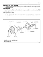
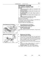
1. STEERING WHEEL PAD (with AIRBAG)
The inflater and bag of the SRS are stored in the steering wheel
pad and cannot be disassembled. The inflater contains a squib,
igniter charge, gas generant, etc., and inflates the bag when
instructed by the airbag sensor assembly.
2. SPIRAL CABLE (in COMBINATION SWITCH)
A spiral cable is used as an electrical joint from the vehicle body
side to the steering wheel.
3. FRONT PASSENGER AIRBAG ASSEMBLY
The inflater and bag of the SRS are stored in the front passen-
ger airbag assembly and cannot be disassembled. The inflater
contains a squib, igniter charge and gas generant, etc., and in-
flates the bag when instructed by the airbag sensor assembly.
4. SIDE AIRBAG ASSEMBLY
The inflater and bag of the SRS side airbag are stored in the
side airbag assembly and cannot be disassembled. The inflater
contains a squib, igniter charge and gas generant, etc., and in-
flates the bag when instructed by the side airbag sensor assem-
bly.
5. SEAT BELT PRETENSIONER
The seat belt pretensioner system is a component of the front
seat outer belt. The pretensioner contains a squib, gas gener-
ant, wire, piston, etc., and operates in the event of a frontal colli-
sion.
H02309
H02266
H08235
H03284
–SUPPLEMENTAL RESTRAINT SYSTEM SRS AIRBAG
RS–3
2148AuthorĂ: DateĂ:
6. SRS WARNING LIGHT
The SRS warning light is located on the combination meter. It
goes on to alert the driver of trouble in the system when a mal-
function is detected in the airbag sensor assembly self–diagno-
sis. In normal operation conditions when the ignition switch is
turned to the ACC or ON position, the light goes on for about 6
seconds and then goes off.
7. AIRBAG SENSOR ASSEMBLY
The airbag sensor assembly is mounted on the floor inside the
lower center finish panel. The airbag sensor assembly consists
of an airbag sensor, safing sensor, diagnosis circuit, ignition
control and drive circuit, etc. It receives signals from the airbag
sensor and judges whether the SRS must be activated or not.
8. FRONT AIRBAG SENSOR
A front airbag sensor is mounted inside each of the side mem-
bers. The sensor unit is a mechanical type. When the sensor
detects deceleration force above a predetermined limit, contact
is made in the sensor, sending a signal to the airbag sensor as-
sembly. The sensor cannot be disassembled.
9. SIDE AIRBAG SENSOR ASSEMBLY
The side airbag sensor assembly is mounted in the LH and RH
center pillars. The side airbag sensor assembly consists of a lat-
eral deceleration sensor, safing sensor and diagnosis circuit,
etc. It receives signals to the airbag sensor assembly to judge
from the side airbag sensors whether the SRS side airbag must
be activated or not.
H08316
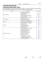
Side Airbag Assembly (LH)
(Squib)
Side Airbag Sensor (LH)
Side Airbag Sensor (RH)
Side Airbag Assembly (RH)
(Squib)
Seat Belt
Pretensioner (RH)
Airbag Sensor
Assembly
Front Passenger Airbag Assembly (Squib)
Spiral Cable
No.1 J/B
2
3
7
8
10
11
12
13
1
4
5
6
9
Steering Wheel
Pad (Squib)
Front Airbag Sensor (RH)
Front Airbag Sensor (LH)
Seat Belt
Pretensioner (LH)
14
15
16
RS–4
–SUPPLEMENTAL RESTRAINT SYSTEM SRS AIRBAG
2149AuthorĂ: DateĂ:
10. TMC made:
SRS CONNECTORS
No. Item Application
(1) Terminal Twin–Lock Mechanism Connectors 1, 2, 3, 4, 5, 6, 7, 8, 9, 10, 11, 12, 13, 14, 15, 16
(2) Airbag Activation Prevention Mechanism Connectors 1, 2, 3, 4, 5, 7, 8, 9, 15, 16
(3) Electrical Connection Check Mechanism Connectors 1, 2, 3
(4) Connector Twin–Lock Mechanism Connectors 5, 6, 7
H08247
Airbag Sensor
Assembly
2
3
1
Side Airbag Assembly (RH)
(Squib)
Seat Belt
Pretensioner (RH)
Side Airbag Sensor (RH)
Front Passenger Airbag
Assembly (Squib)
Spiral Cable
Steering Wheel
Pad (Squib)
No.1 J / B
Side Airbag Sensor (LH)
Side Airbag Assembly (LH)
(Squib)
4
5
6
7
14
9
10
11
12
13
8
15
Seat Belt
Pretensioner (LH)
1617
18
Front Airbag Sensor (RH)
Front Airbag Sensor (LH)
–SUPPLEMENTAL RESTRAINT SYSTEM SRS AIRBAG
RS–5
2150AuthorĂ: DateĂ:
11. TMMK made:
SRS CONNECTORS
No. Item Application
(1) Terminal Twin–Lock Mechanism
Connectors 1, 2, 3, 4, 5, 6, 7, 8, 9, 10, 11, 12, 13, 14, 15, 16,
17, 18
(2) Airbag Activation Prevention Mechanism Connectors 1, 2, 3, 4, 5, 7, 8, 9, 15, 16, 17, 18
(3) Electrical Connection Check Mechanism Connectors 1, 2, 3
(4) Connector Twin–Lock Mechanism Connectors 5, 6, 7
Z05953
Spacer
Housing
Female Male
R10587
When Connector is Connected When Connector is Disconnected
Short Spring Plate
Housing
Housing
Terminal
Connectors
Short Spring Plate
Squib
Closed Circuit
Squib
Short Spring Plate ON
Contacting Male Terminal
Short Spring Plate
RS–6
–SUPPLEMENTAL RESTRAINT SYSTEM SRS AIRBAG
2151AuthorĂ: DateĂ:
(a) All connectors in the SRS are colored in yellow to distin-
guish them from other connectors. Connectors having
special functions and specifically designed for the SRS
are used in the locations shown on the previous page to
ensure high reliability. These connectors use durable
gold–plated terminals.
(1) Terminal twin–lock mechanism
Each connector has a two–piece component con-
sisting of a housing and a spacer. This design en-
ables the terminal to be locked securely by two lock-
ing devices (the retainer and the lance) to prevent
terminals from coming out.
(2) Airbag activation prevention mechanism
Each connector contains a short spring plate. When
the connector is disconnected, the short spring
plate automatically connects positive (+) terminal
and negative (–) terminal of the squib.
R12076
Airbag Sensor Assembly
Disconnection
Detection
Pin
SRS
Warning
Light
H01315
Terminal for Diagnosis
Disconnection Detection Pin
FHalf Connection FComplete Connection
Terminal for
Diagnosis
–SUPPLEMENTAL RESTRAINT SYSTEM SRS AIRBAG
RS–7
2152AuthorĂ: DateĂ:
HINT:
The type of connector is shown in the diagram on the previous
page.
(3) Electrical connection check mechanism
This mechanism electrically checks that connectors
are connected correctly and completely. The electri-
cal connection check mechanism is designed so
that the disconnection detection pin connects with
the diagnosis terminals when the connector hous-
ing lock is locked.
HINT:
The connectors shown in this illustration are connectors, ”1”, ”2”
and ”3” in step 10 and 11.
AB0089
Secondary Lock
Primary Lock
Lock
Lock
Primary Lock Incomplete
(Secondary Lock Prevented)
Primary Lock Complete
(Secondary Lock Permitted)
Twin–Lock Completed
Z14034
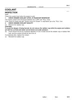
Fig.1
Fig.2
Power Source
Safing
Sensor
Squibs
Deceleration
Sensor
RS–8
–SUPPLEMENTAL RESTRAINT SYSTEM SRS AIRBAG
2153AuthorĂ: DateĂ:
(4) Connector twin–lock mechanism
With this mechanism connectors (male and female
connectors) are locked by 2 locking devices to in-
crease the connection reliability. If the primary lock
is incomplete, ribs interfere and prevent the sec-
ondary lock.
(b) When the vehicle is involved in a frontal collision in the
hatched area (Fig. 1) and the shock is larger than the pre-
determined level, the SRS is activated automatically. A
safing sensor is designed to go on at a smaller decelera-
tion rate than the airbag sensor. As illustrated in Fig. 2,
ignition is caused when current flows to the squib, which
happens when a safing sensor and the deceleration sen-
sor go on simultaneously. When a deceleration force acts
on the sensors, 2 squibs in the driver airbag and front pas-
senger airbag ignite and generate gas. The gas discharg-
ing into the driver airbag and front passenger airbag rap-
idly increases the pressure inside the bags, breaking
open the steering wheel pad and instrument panel door.
Bag inflation then ends, and the bags deflate as the gas
is discharged through discharge holes at the bag’s rear or
side.
H01581
Outer
H01582
Lock of connector is released
Disconnection is completed
H01583
Outer
Outer
–SUPPLEMENTAL RESTRAINT SYSTEM SRS AIRBAG
RS–9
2154AuthorĂ: DateĂ:
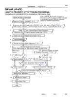
12. DISCONNECTION OF FRONT AIRBAG SENSOR AND
SIDE AIRBAG SENSOR CONNECTOR
(a) While holding both flank sides of the outer, slide the outer
to the direction shown by an arrow.
(b) Lock of the connectors is released, then disconnect the
connectors.
HINT:
Make sure to hold both flank sides of the outer. If holding the top
and bottom sides, it will obstruct disconnection.
13. CONNECTION OF FRONT AIRBAG SENSOR AND
SIDE AIRBAG SENSOR CONNECTOR
(a) Align the male connector (of the side of sensor) and fe-
male connector in the same direction as shown in the il-
lustration and fit in them without rubbing.
(b) As they are fitted in, the outer slides rearward. Press it un-
til the outer returns to its original position again.
If fitting stops half way, connectors will separate.
(c) Make sure to insert until they are locked. After fitting in,
pull them slightly to check that they are locked. (When
locked, make sure that the outer returns to its original
position and sound at the time of fitting in can be heard.)
HINT:
Do not fit in while holding the outer.
When fitting in, the outer slides. Do not touch it.
H01584
Slider
Disconnection is completed
Slider
RS–10
–SUPPLEMENTAL RESTRAINT SYSTEM SRS AIRBAG
2155AuthorĂ: DateĂ:
14. DISCONNECTION OF SIDE AIRBAG CONNECTOR
(a) Place a finger on the slider.
(b) Slide the slider to release lock.
(c) Disconnect the connector.
H01585
Slider
Slider
–SUPPLEMENTAL RESTRAINT SYSTEM SRS AIRBAG
RS–11
2156AuthorĂ: DateĂ:
15. CONNECTION OF SIDE AIRBAG CONNECTOR
(a) Align a lock part of male connector and a slider of female
connector in the same direction as shown in the illustra-
tion, fit in them without rubbing.
(b) Make sure to insert until they are locked. After fitting in pull
them slightly to check that they are locked. (When locked,
make sure that the outer returns to its original position and
sound at the time of fitting in can be heard.)
HINT:
As the slider slides, do not touch it.
Be careful not to deform the release board. If the release
board is deformed, replace it with a new one.
H01586
Slider
Disconnection is completed
Slider
RS–12
–SUPPLEMENTAL RESTRAINT SYSTEM SRS AIRBAG
2157AuthorĂ: DateĂ:
16. DISCONNECTION OF CONNECTORS FOR FRONT
PASSENGER AIRBAG ASSEMBLY
(a) Place a finger on the slider.
(b) Slide the slider to release lock.
(c) Disconnect the connector.
H01587
Slider
Slider
–SUPPLEMENTAL RESTRAINT SYSTEM SRS AIRBAG
RS–13
2158AuthorĂ: DateĂ:
17. CONNECTION OF CONNECTORS FOR FRONT PAS-
SENGER AIRBAG ASSEMBLY
(a) Align a lock part of male connector and a slider of female
connector in the same direction as shown in the illustra-
tion, fit in them without rubbing.
(b) Make sure to insert until they are locked. After fitting in pull
them slightly to check that they are locked. (When locked,
make sure that the outer returns to its original position and
sound at the time of fitting in can be heard.)
HINT:
As the slider slides, do not touch it.
Be careful not to deform the release board. If the release
board is deformed, replace it with a new one.
RS00Y–20
H03294
Column Upper Cover
Spiral Cable
Steering Wheel
Steering Wheel Pad
Column Lower Cover
N·m (kgf·cm, ft·lbf) : Specified torque
7.1 (72, 63 in.·lbf)
35 (360, 26)
Steering Wheel Lower
No.2 Cover
Steering Wheel Lower
No.2 Cover
Torx Screw
RS–14
–SUPPLEMENTAL RESTRAINT SYSTEM STEERING WHEEL PAD AND SPIRAL CABLE
2159AuthorĂ: DateĂ:
STEERING WHEEL PAD AND SPIRAL CABLE
COMPONENTS
RS00Z–14
–SUPPLEMENTAL RESTRAINT SYSTEM STEERING WHEEL PAD AND SPIRAL CABLE
RS–15
2160AuthorĂ: DateĂ:
REMOVAL
HINT:
For step 1 to 4, refer to page SR–11.
1. REMOVE STEERING WHEEL PAD
2. REMOVE STEERING WHEEL
3. REMOVE UPPER AND LOWER COLUMN COVERS
4. REMOVE SPIRAL CABLE
RS010–19
W03512
W03513
W03521
Horn Button
Contact Plate
RS–16
–SUPPLEMENTAL RESTRAINT SYSTEM STEERING WHEEL PAD AND SPIRAL CABLE
2161AuthorĂ: DateĂ:
INSPECTION
1. VEHICLE NOT INVOLVED IN COLLISION
(a) Do a diagnostic system check.
(See page DI–626)
(b) Do a visual check which includes the following items with
the steering wheel pad (with airbag) installed in the ve-
hicle.
Check cuts, minute cracks or marked discoloration on the
steering wheel pad top surface and in the grooved por-
tion.
2. VEHICLE INVOLVED IN COLLISION AND AIRBAG IS
NOT DEPLOYED
(a) Do a diagnostic system check.
(See page DI–626)
(b) Do a visual check which includes the following items with
the steering wheel pad (with airbag) removed from the ve-
hicle.
F Check cuts, minute cracks or marked discoloration
on the steering wheel pad top surface and in the
grooved portion.
F Check cuts and cracks in wire harnesses, and chip-
ping in connectors.
F Check the deformation of the horn button contact
plate on the steering wheel.
HINT:
F If the horn button contact plate of the steering wheel is de-
formed, never repair it. Always replace the steering wheel
assembly with a new one.
W03651
–SUPPLEMENTAL RESTRAINT SYSTEM STEERING WHEEL PAD AND SPIRAL CABLE
RS–17
2162AuthorĂ: DateĂ:
F There should be no interference between the steering
wheel pad and steering wheel, and the clearance should
be uniform all the way around when the new steering
wheel pad is installed on the steering wheel.
CAUTION:
For removal and installation of the steering wheel pad, see
page SR–11 and SR–16, and be sure to follow the correct
procedure.
3. VEHICLE INVOLVED IN COLLISION AND AIRBAG IS
DEPLOYED
(a) Do a diagnostic system check.
(See page DI–626)
(b) Do a visual check which includes the following items with
the steering wheel pad (with airbag) removed from the ve-
hicle.
F Check the deformation on the horn button contact
plate of the steering wheel.
F Check the damage on the spiral cable connector
and wire harness.
HINT:
F If the horn button contact plate of the steering wheel is de-
formed, never repair it. Always replace the steering wheel
assembly with a new one.
F There should be no interference between the steering
wheel pad and steering wheel, and the clearance should
be uniform all the way around when the new steering
wheel pad is installed on the steering wheel.
RS011–19
AB0152
SST
RS–18
–SUPPLEMENTAL RESTRAINT SYSTEM STEERING WHEEL PAD AND SPIRAL CABLE
2163AuthorĂ: DateĂ:
DISPOSAL
HINT:
When scrapping vehicle equipped with an SRS or disposing of
a steering wheel pad (with airbag), always first deploy the air-
bag in accordance with the procedure described below. If any
abnormality occurs with the airbag deployment, contact the
SERVICE DEPT. of TOYOTA MOTOR SALES, U.S.A., INC.
When disposing of a steering wheel pad with an airbag
deployed in a collision, follow the same procedure given in step
1–(d) in ”DISPOSAL”.
CAUTION:
F Never dispose of a steering wheel pad which has an
undeployed airbag.
F The airbag produces a sizeable exploding sound
when it deploys, so perform the operation out–of–
doors and where it will not create a nuisance to
nearby residents.
F When deploying the airbag, always use the specified
SST (SRS Airbag Deployment Tool). Perform the op-
eration in a place away from electrical noise.
SST 09082–00700
F When deploying an airbag, perform the operation at
least 10 m (33 ft) away from the steering wheel pad.
F The steering wheel pad is very hot when the airbag is
deployed, so leave it alone for at least 30 minutes af-
ter deployment.
F Use gloves and safety glasses when handling a steer-
ing wheel pad with the deployed airbag.
F Always wash your hands with water after completing
the operation.
F Do not apply water, etc. to a steering wheel pad with
the deployed airbag.
AB0158
SST
Battery
AB0152
SST
AB0158
SST
Battery
H01580
SST
W03515
–SUPPLEMENTAL RESTRAINT SYSTEM STEERING WHEEL PAD AND SPIRAL CABLE
RS–19
2164AuthorĂ: DateĂ:
1. AIRBAG DEPLOYMENT WHEN SCRAPPING VE-
HICLE
HINT:
Have a battery ready as the power source to deploy the airbag.
(a) Check functioning of the SST.
CAUTION:
When deploying the airbag, always use the specified SST:
SRS Airbag Deployment Tool.
SST 09082–00700
(1) Connect the SST to the battery.
Connect the red clip of the SST to the battery posi-
tive (+) terminal and the black clip to the battery neg-
ative (–) terminal.
HINT:
Do not connect the yellow connector which will be connected
with the supplemental restraint system.
(2) Check functioning of the SST.
Press the SST activation switch, and check that the
LED of the SST activation switch lights up.
CAUTION:
If the LED lights up when the activation switch is not being
pressed, SST malfunction is probable, so definitely do not
use the SST.
(b) Install the SST.
CAUTION:
Check that there is no looseness in the steering wheel and
steering wheel pad.
(1) Remove the steering column lower cover.
Remove the 3 screws and steering column lower
cover as shown in the illustration.
(2) Disconnect the airbag connector of the spiral cable.
W03508
SST
R13455
10 m (33 ft) or more
R06753
RS–20
–SUPPLEMENTAL RESTRAINT SYSTEM STEERING WHEEL PAD AND SPIRAL CABLE
2165AuthorĂ: DateĂ:
(3) Connect the SST connector to the airbag connector
of the spiral cable.
SST 09082–00700
(4) Move the SST at least 10 m (33 ft) away from the
front of the vehicle.
(5) Close all the doors and windows of the vehicle.
NOTICE:
Take care not to damage the SST wire harness.
(6) Connect the SST red clip to the battery positive (+)
terminal and the black clip to the negative (–) termi-
nal.
(c) Deploy the airbag.
(1) Confirm that no one is inside the vehicle or within 10
m (33 ft) area around the vehicle.
(2) Press the SST activation switch and deploy the air-
bag.
HINT:
The airbag deploys simultaneously as the LED of the SST ac-
tivation switch lights up.
(d) Dispose of steering wheel pad (with airbag).
CAUTION:
F The steering wheel pad is very hot when the airbag is
deployed, so leave it alone for at least 30 minutes af-
ter deployment.
F Use gloves and safety glasses when handling a steer-
ing wheel pad with the deployed airbag.
F Always wash your hands with water after completing
the operation.
F Do not apply water, etc. to a steering wheel pad with
the deployed airbag.
(1) When scrapping a vehicle, deploy the airbag and
scrap the vehicle with the steering wheel pad still
installed.
(2) When moving a vehicle for scrapping which has a
steering wheel pad with deployed airbag, use
gloves and safety glasses.
W03520
Inflacter Cover
Connector
AB0163
Wire Harness
Diameter
Stripped Wire Harness Section
H06693
L
M
–SUPPLEMENTAL RESTRAINT SYSTEM STEERING WHEEL PAD AND SPIRAL CABLE
RS–21
2166AuthorĂ: DateĂ:
2. DEPLOYMENT WHEN DISPOSING OF STEERING
WHEEL PAD ONLY
NOTICE:
F When disposing of the steering wheel pad (with air-
bag) only, never use the customers vehicle to deploy
the airbag.
F Be sure to follow the procedure given below when de-
ploying the airbag.
HINT:
Have a battery ready as the power source to deploy the airbag.
(a) Remove the steering wheel pad.
(See page SR–11)
CAUTION:
When storing the steering wheel pad, keep the upper sur-
face of the pad facing upward.
(b) Remove the steering wheel pad connector.
Remove the connector on the rear surface of the steering
wheel pad from the bracket.
(c) Using a service–purpose wire harness, tie down the
steering wheel pad to the disc wheel.
Wire harness: Stripped wire harness section
1.25 mm
2
or more (0.0019 in
2
. or more).
CAUTION:
If a wire harness which is too thin or some other thing is
used to tie down the steering wheel pad, it may be snapped
by the shock when the airbag is deployed. This is highly
dangerous. Always use a wire harness for vehicle use
which is at least 1.25 mm
2
(0.0019 in
2
).
HINT:
To calculate the square of the stripped wire harness section:
Square = 3.14 x (Diameter)
2
divided by 4
(1) Install the 2 bolts with washers in the 2 bolt holes in
the steering wheel pad.
Bolt:
L: 35.0 mm (1.387 in.)
M: 6.0 mm (0.236 in.)
Pitch: 1.0 mm (0.039 in.)
NOTICE:
F Tighten the bolts by hand until the bolts become diffi-
cult to turn.
F Do not tighten the bolts too much.
H06694
2 Times or more
H06695
AB0158
SST
Battery
RS–22
–SUPPLEMENTAL RESTRAINT SYSTEM STEERING WHEEL PAD AND SPIRAL CABLE
2167AuthorĂ: DateĂ:
(2) Using 3 wire harnesses, wind the wire harness at
least 2 times each around the bolts installed on the
left and right sides of the steering wheel pad.
CAUTION:
F Tightly wind the wire harness around the bolts so that
there is no slack.
F If there is slack in the wire harness, the steering wheel
pad may come loose due to the shock when the air-
bag is deployed. This is highly dangerous.
(3) Face the upper surface of the steering wheel pad
upward. Separately tie the left and right sides of the
steering wheel pad to the disc wheel through the
hub nut holes. Position the steering wheel pad con-
nector so that it hangs downward through a hub
hole in the disc wheel.
CAUTION:
F Make sure that the wire harness is tight. It is very dan-
gerous when looseness in the wire harness results in
the steering wheel pad coming free through the shock
from the airbag deploying.
F Always tie down the steering wheel pad with the pad
side facing upward. It is very dangerous if the steer-
ing wheel pad is tied down with the metal surface fac-
ing upward as the wire harness will be cut by the
shock from the airbag deploying and the steering
wheel pad will be thrown into the air.
NOTICE:
The disc wheel will be marked by airbag deployment, so
when disposing of the airbag use a redundant disc wheel.
(d) Check functioning of the SST. (See step 1–(a))
SST 09082–00700
H06696
SST
H00401
Weight
x
y
y
R04211
Inner Diam.
Tires
(3 or More)
Width
–SUPPLEMENTAL RESTRAINT SYSTEM STEERING WHEEL PAD AND SPIRAL CABLE
RS–23
2168AuthorĂ: DateĂ:
(e) Install the SST.
CAUTION:
Place the disc wheel on the level ground.
(1) Connect the connector of SST to the steering wheel
pad connector.
SST 09082–00700
NOTICE:
To avoid damaging the SST connector and wire harness,
do not lock the secondary lock of the twin lock. Also, se-
cure some slack for the SST wire harness inside the disc
wheel.
(2) Move the SST to at least 10 m (33 ft) away from the
steering wheel pad tied down on the disc wheel.
(f) Cover the steering wheel pad with a cardboard box or
tires.
F Covering method using a cardboard box:
Cover the steering wheel pad with the cardboard
box and weight the cardboard box down in 4 places
with at least 190 N (20 kg, 44 lb).
Size of cardboard box:
Must exceed the following dimensions:
x= 460 mm (18.11 in.)
When dimension of the cardboard box exceeds the di-
ameter of the disc wheel with tire to which the steer-
ing wheel pad is tied
x= 460 mm (18.11 in.) + width of tire
y= 650 mm (25.59 in.)
NOTICE:
If a cardboard box smaller than the specified size is used,
the cardboard box will be broken by the shock from the air-
bag deployment.
F Covering method using tires:
Place at least 3 tires without disc wheel on top of the
disc wheel with tire to which the steering wheel pad
is tied.
Tire size: Must exceed the following dimensions–
Width: 185 mm (7.87 in.)
Inner diameter: 360 mm (14.17 in.)
R13763
10 m (33 ft) or more
AB0166
RS–24
–SUPPLEMENTAL RESTRAINT SYSTEM STEERING WHEEL PAD AND SPIRAL CABLE
2169AuthorĂ: DateĂ:
CAUTION:
Do not use tires with disc wheels.
NOTICE:
The tires may be marked by the airbag deployment, so use
the redundant tires.
(g) Deploy the airbag.
(1) Connect the SST red clip to the battery positive (+)
terminal and the black clip to the battery negative
(–) terminal.
(2) Check that no one is within 10 m (33 ft) area around
the disc wheel which the steering wheel pad is tied
to.
(3) Press the SST activation switch and deploy the air-
bag.
HINT:
The airbag deploys simultaneously as the LED of the SST ac-
tivation switch lights up.
(h) Dispose of the steering wheel pad (with airbag).
CAUTION:
F The steering wheel pad is very hot when the airbag is
deployed, so leave it alone for at least 30 minutes af-
ter deployment.
F Use gloves and safety glasses when handling a steer-
ing wheel pad with deployed airbag.
F Always wash your hands with water after completing
the operation.
F Do not apply water, etc. to a steering wheel pad with
deployed airbag.
(1) Remove the steering wheel pad from the disc
wheel.
(2) Place the steering wheel pad in a vinyl bag, tie the
end tightly and dispose of it in the same way as oth-
er general parts disposal.
RS012–19
–SUPPLEMENTAL RESTRAINT SYSTEM STEERING WHEEL PAD AND SPIRAL CABLE
RS–25
2170AuthorĂ: DateĂ:
REPLACEMENT
REPLACEMENT REQUIREMENTS
In the following cases, replace the steering wheel pad, steering wheel or spiral cable.
Case Replacing part
If the airbag has been deployed. Steering wheel pad
If the steering wheel pad has been found to be faulty in troubleshooting. Steering wheel pad
If the spiral cable has been found to be faulty in troubleshooting. Spiral cable
If the steering wheel pad has been found to be faulty during checking items.
(See page RS–16)
Steering wheel pad
If the steering wheel has been found to be faulty during checking items.
(See page RS–16)
Steering wheel
If the spiral cable has been found to be faulty during checking items.
(See page RS–16)
Spiral cable
If the steering wheel pad has been dropped. Steering wheel pad
CAUTION:
For removal and installation of the steering wheel pad, see page SR–11 and SR–16. Be sure to follow
the correct procedure.