Camry Repair Manual SUSPENSION AXLE
Bạn đang xem bản rút gọn của tài liệu. Xem và tải ngay bản đầy đủ của tài liệu tại đây (1.24 MB, 97 trang )
SA077–01
–SUSPENSION AND AXLE TROUBLESHOOTING
SA–1
1952A uthorĂ: DateĂ:
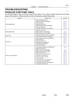
TROUBLESHOOTING
PROBLEM SYMPTOMS TABLE
Use the table below to help you find the cause of the problem. The numbers indicate the priority of the likely
cause of the problem. Check each part in order. If necessary, replace these parts.
Symptom Suspect Area See page
Wander/pulls
1. Tire (Worn or improperly inflated)
2. Wheel alignment (Incorrect)
3. Steering linkage (Loosen or worn)
4. Hub bearings (Worn)
5. Suspension parts (Worn)
6. Steering gear (Out of adjustment or broken)
SA–2
SA–4
SA–7
–
SA–10
–
–
Bottoming
1. Vehicle (Overloaded)
2. Spring (Weak)
3. Shock absorber (Worn)
–
SA–33
SA–56
SA–33
SA–56
Sways/pitches
1. Tire (Worn or improperly inflated)
2. Stabilizer bar (Bent or broken)
3. Shock absorber (Worn)
SA–2
SA–47
SA–69
SA–33
SA–56
Front wheel shimmy
1. Tire (Worn or improperly inflated)
2. Wheels (Out of balance)
3. Shock absorber (Worn)
4. Wheel alignment (Incorrect)
5. Ball joints (Worn)
6. Hub bearings (Worn)
7. Steering linkage (Loosen or worn)
8. Steering gear (Out of adjustment or broken)
SA–2
SA–2
SA–33
SA–56
SA–4
SA–7
SA–43
SA–10
–
–
Abnormal tire wear
1. Tire (Worn or improperly inflated)
2. Wheels (Out of balance)
3. Suspension parts (Worn)
4. Shock absorber (Worn)
SA–2
SA–2
–
SA–33
SA–56
R03031
SA078–01
R15157
Front
R07928
SA–2
–SUSPENSION AND AXLE TIRE AND WHEEL
1953AuthorĂ: DateĂ:
TIRE AND WHEEL
INSPECTION
1. INSPECT TIRE
(a) Check the tires for wear and proper inflation pressure.
Cold inflation pressure:
Normal driving
Tire size
Front, Rear
kPa (kgf/cm
2
or bar, psi)
P195/70R14 90S, 90H 210 (2.1, 30)
P205/65R15 92H
*
1
220 (2.2, 32)
*
2
200 (2.0, 29)
*
1
: For all loads including full rated loads
*
2
: For reduced loads (1 to 4 passengers)
Trailer towing
Tire size
Front, Rear
kPa (kgf/cm
2
or bar, psi)
P195/70R14 90S
*
1
210 (2.1, 30)
*
2
240 (2.4, 36)
P205/65R15 92H
*
1
220 (2.2, 32)
*
2
240 (2.4, 36)
*
1
: For driving under 160 km/h (100 mph)
*
2
: For driving at 160 km/h (100 mph) or over
(b) Check the tire runout.
Tire runout: 1.0 mm (0.039 in.) or less
2. ROTATING TIRES
HINT:
See the illustration for where to rotate each tire.
3. INSPECT WHEEL BALANCE
(a) Check and adjust the Off–the–car balance.
(b) If necessary, check and adjust the On–the–car balance.
Imbalance after adjustment:
8.0 g (0.018 lb) or less
W03084
–SUSPENSION AND AXLE TIRE AND WHEEL
SA–3
1954AuthorĂ: DateĂ:
4. CHECK WHEEL BEARING LOOSENESS
(a) Check the backlash in the bearing shaft direction.
Maximum: 0.05 mm (0.0020 in.)
(b) Check the axle hub deviation.
Maximum: 0.05 mm (0.0020 in.)
5. CHECK FRONT SUSPENSION FOR LOOSENESS
6. CHECK STEERING LINKAGE FOR LOOSENESS
7. CHECK BALL JOINT FOR LOOSENESS
8. CHECK SHOCK ABSORBER WORKS PROPERLY
z Check for oil leaks
z Check mounting bushings for wear
z Check front and rear of the vehicle for bounce
W03085
Front
R03030
Rear
SA079–01
Z03382
SA3213
AB
C
D
Front
SA–4
–SUSPENSION AND AXLE FRONT WHEEL ALIGNMENT
1955A uthorĂ: DateĂ:
FRONT WHEEL ALIGNMENT
INSPECTION
1. MEASURE VEHICLE HEIGHT
Tire size Front*
1
mm (in.) Rear*
2
mm (in.)
195/70R14 212 (8.35) 264 (10.39)
205/65R15 215 (8.46) 266 (10.49)
*
1
: Front measuring point
Measure from the ground to the center of the front side lower
suspension arm mounting bolt.
*
2
: Rear measuring point
Measure from the ground to the center of the strut rod mounting
bolt.
NOTICE:
Before inspecting the wheel alignment, adjust the vehicle
height to the specification.
If the vehicle height is not within the specification, try to adjust
it by pushing down on or lifting the body.
2. INSTALL CAMBER–CASTER–KINGPIN GAUGE
ONTO VEHICLE OR POSITION VEHICLE ON WHEEL
ALIGNMENT TESTER
Follow the specific instructions of the equipment manufacturer.
3. INSPECT CAMBER, CASTER AND STEERING AXIS
INCLINATION
5S–FE 1MZ–FE
Camber
Left–right error
–0°36’ ± 45’
(–0.6° ± 0.75°)
45’ (0.75°) or less
–0°37’ ± 45’
(–0.62° ± 0.75°)
45’ (0.75°) or less
Caster
Left–right error
2°10’ ± 45’
(2.17° ± 0.75°)
45’ (0.75°) or less
2°11’ ± 45’
(2.18° ± 0.75°)
45’ (0.75°) or less
Steering axis inclination
Left–right error
13°01’ ± 45’
(13.02° ± 0.75°)
45’ (0.75°) or less
13°04’ ± 45’
(13.07° ± 0.75°)
45’ (0.75°) or less
HINT:
If the caster and steering axis inclination are not within the spec-
ification, after the camber has correctly adjusted, recheck the
suspension parts for damaged and/or worn out parts.
4. INSPECT TOE–IN
Toe–in
(Total)
A + B: 0° ± 12’ (0° ± 0.2°)
C – D: 0 ± 2 mm (0 ± 0.08 in.)
If the toe–in is not within the specification, adjust it at the rack
ends.
W03086
F02267
1
2
F01195
Bolt
Adjusting
Value
Set Bolt
15’
30’
Adjusting Bolt
90105–15001 90105–15004 90105–15005 90105–15006
45’
1°00’
1°15’
1°30’
12121212
1 Dot 2 Dots 3 Dots
–SUSPENSION AND AXLE FRONT WHEEL ALIGNMENT
SA–5
1956A uthorĂ: DateĂ:
5. ADJUST CAMBER
NOTICE:
After the camber has been adjusted, inspect the toe–in.
(a) Remove the front wheels and speed sensor clamp.
(b) Remove the 2 nuts on the lower side of the shock absorb-
er.
(c) Coat the threads of the nuts with engine oil.
(d) Temporarily install the 2 nuts.
(e) Adjust the camber by pushing or pulling the lower side of
the shock absorber in the direction in which the camber
adjustment is required.
(f) Tighten the nuts.
Torque: 211 N·m (2,150 kgf·cm, 156 ft·lbf)
(g) Install the front wheels.
Torque: 103 N·m (1,050 kgf·cm, 76 ft·lbf)
(h) Check the camber.
HINT:
z Try to adjust the camber to the center value.
z Adjusting value for the set bolts is 6’ – 30’ (0.1° – 0.5°).
If the camber is not within the specification, using the table be-
low, estimate for how much additional camber adjustment will
be required, and select the camber adjusting bolt.
(i) Follow the above mentioned steps again. Between step
(b) and (c), exchange 1 or 2 selected bolts.
HINT:
When exchanging the 2 bolts, exchange 1 bolt for each time.
W03088
SA0028
A: Inside
B: Outside
AB
Front
BA
SA–6
–SUSPENSION AND AXLE FRONT WHEEL ALIGNMENT
1957A uthorĂ: DateĂ:
6. ADJUST TOE–IN
(a) Remove the boot clamps.
(b) Loosen the tie rod end lock nuts.
(c) Turn the left and right rack ends an equal amount to adjust
the toe–in.
HINT:
z Try to adjust the toe–in to the center value.
z Make sure that the length of the left and right rack ends
is the same.
Rack end length difference:
1.5 mm (0.059 in.) or less
(d) Torque the tie rod end lock nuts.
Torque: 74 N·m (750 kgf·cm, 54 ft·lbf)
(e) Place the boot on the seat and install the clip it.
HINT:
Make sure that the boots are not twisted.
7. INSPECT WHEEL ANGLE
Turn the steering wheel fully, and measure the turning angle.
Tire size Inside wheel
Outside wheel
<Reference>
195/70R14
37°12’ ± 2°
(37.2° ± 2°)
32°21’
(32.45°)
205/65R15
35°47’ ± 2°
(35.78° ± 2°)
31°25’
(31.42°)
If the wheel angles differ from the specification, check the left
and right rack end length.
SA07A–01
SA3213
A
B
C
D
Front
W03090
–SUSPENSION AND AXLE REAR WHEEL ALIGNMENT
SA–7
1958A uthorĂ: DateĂ:
REAR WHEEL ALIGNMENT
INSPECTION
1. MEASURE VEHICLE HEIGHT
Vehicle height: See page SA–4
NOTICE:
Before inspecting the wheel alignment, adjust the vehicle
height to specification.
2. INSTALL CAMBER – CASTER – KINGPIN GAUGE
ONTO VEHICLE OR POSITION VEHICLE ON WHEEL
ALIGNMENT TESTER
Follow the specific instructions on the equipment manufacturer.
3. INSPECT CAMBER
5S–FE 1MZ–FE
Camber
Left–right error
–0°42’ ± 45’
(–0.7° ± 0.75°)
45’ (0.75°) or less
–0°45’ ± 45’
(–0.75° ± 0.75°)
45’ (0.75°) or less
HINT:
Camber in not adjustable, it measurement is not within the
specifications, inspect the suspension parts for damaged and/
or worn–out parts and replace them as necessary.
4. INSPECT TOE–IN
Toe–in
(Total)
A + B: 0°24’ ± 12’ (0.4° ± 0.2°)
C – D: 4 ± 2 mm (0.16 ± 0.08 in.)
If the toe–in is not within the specification, adjust it at the No.2
lower suspension arm.
5. ADJUST TOE–IN
(a) Measure the length of the left and right No.2 lower sus-
pension arms.
No.2 lower suspension arm length difference:
1 mm (0.04 in.) or less
If the left–right difference is larger than the specification, adjust
the length.
W03091
SA–8
–SUSPENSION AND AXLE REAR WHEEL ALIGNMENT
1959A uthorĂ: DateĂ:
(b) Loosen the lock nuts.
(c) Turn the left and right lower suspension arms an equal
amount to adjust toe–in.
HINT:
z Try to adjust the toe–in to the center value.
z One turn of the each adjusting tube will adjust the toe–in
about 36’ (0.6°, 6.7 mm, 0.264 in.).
(d) Torque the lock nuts.
Torque: 56 N·m (570 kgf·cm, 41 ft·lbf)
SA07B–01
W03092
Front Shock Absorber
Tie Rod End
Front Drive Shaft
Brake Caliper
ABS Speed Sensor
Lower Suspension Arm
Lock Cap
z Snap Ring
z Dust Deflector
Steering Knuckle
Dust Cover
zBearing
Lower Ball Joint
Axle Hub
127 (1,300, 94)
294 (3,000, 217)
107 (1,090,79)
8.0 (82, 71 in.·lbf)
123 (1,250, 90)
z Cotter pin
z Cotter pin
z Cotter pin
Hub Bolt
Disc
N·m (kgf·cm, ft·lbf) : Specified torque
z Non–reusable part
211 (2,150, 156)
49 (500, 36)
8.3 (85, 74 in.·lbf)
–SUSPENSION AND AXLE FRONT AXLE HUB
SA–9
1960AuthorĂ: DateĂ:
FRONT AXLE HUB
COMPONENTS
SA07C–01
W03084W03084
W03093
W03139
W03094
SST
SA–10
–SUSPENSION AND AXLE FRONT AXLE HUB
1961AuthorĂ: DateĂ:
REMOVAL
1. REMOVE FRONT WHEEL
Torque: 103 N·m (1,050 kgf·cm, 76 ft·lbf)
2. CHECK BEARING BACKLASH AND AXLE HUB DEVI-
ATION
(a) Remove the 2 bolts, brake caliper and disc.
(b) Support the brake caliper securely.
(c) Using a dial indicator near the center of the axle hub and
check the backlash in the bearing shaft direction.
Maximum: 0.05 mm (0.0020 in.)
If the backlash exceeds the maximum, replace the bearing.
(d) Using a dial indicator, check the deviation at the surface
of the axle hub outside the hub bolt.
Maximum: 0.05 mm (0.0020 in.)
If the deviation exceeds the maximum, replace the bearing.
(e) Install the disc, 2 bolts and brake caliper.
Torque: 107 N·m (1,090 kgf·cm, 79 ft·lbf)
3. REMOVE DRIVE SHAFT LOCK NUT
(a) Remove the cotter pin and lock cap.
(b) With applying the brakes, remove the nut.
Torque: 294 N·m (3,000 kgf·cm, 217 ft·lbf)
(c) Remove the brake caliper and disc.
4. w/ ABS:
REMOVE ABS SPEED SENSOR AND WIRE HARNESS
CLAMP
Torque: 8.0 N·m (82 kgf·cm, 71 in.·lbf)
5. LOOSEN 2 NUTS ON LOWER SIDE OF SHOCK AB-
SORBER
Torque: 211 N·m (2,150 kgf·cm, 156 ft·lbf)
HINT:
z Do not remove the bolts.
z At the time of installation, coat the nut’s thread with en-
gine oil.
6. DISCONNECT TIE ROD END FROM STEERING
KNUCKLE
(a) Remove the cotter pin and nut.
Torque: 49 N·m (500 kgf·cm, 36 ft·lbf)
(b) Using SST, disconnect the tie rod end from the steering
knuckle.
SST 09610–20012
W03095
–SUSPENSION AND AXLE FRONT AXLE HUB
SA–11
1962AuthorĂ: DateĂ:
7. DISCONNECT LOWER BALL JOINT FROM LOWER
ARM
Remove the 2 nuts and bolt.
Torque: 127 N·m (1,300 kgf·cm, 94 ft·lbf)
8. REMOVE STEERING KNUCKLE WITH AXLE HUB
(a) Remove the 2 bolts on the lower side of the shock absorb-
er.
(b) Remove the steering knuckle with the axle hub.
NOTICE:
Be careful not to damage the oil seal with drive shaft.
SA07D–01
R08859
SST
R00789
SST
W02110
SST
R11486
SST
SST
SA–12
–SUSPENSION AND AXLE FRONT AXLE HUB
1963AuthorĂ: DateĂ:
DISASSEMBLY
1. REMOVE DUST DEFLECTOR
Using a screwdriver, remove the dust deflector.
2. REMOVE LOWER BALL JOINT
(a) Remove the cotter pin and nut.
(b) Using SST, remove the lower ball joint.
SST 09628–62011
3. REMOVE AXLE HUB
(a) Using SST, remove the axle hub.
SST 09520–00031
(b) Using SST and a press, remove the inner race (outside)
from the axle hub.
SST 09950–00020, 09950–60010 (09951–00400),
09950–70010 (09951–07100)
4. REMOVE DUST COVER
Using a torx wrench (T30), remove the 4 bolts and dust cover.
5. REMOVE BEARING FROM STEERING KNUCKLE
(a) Using snap ring pliers, remove the snap ring.
(b) Place the inner race on the outside of the bearing.
(c) Using SST and a press, remove the bearing.
SST 09310–35010, 09527–17011
SA07E–01
R00792
SST
R08860
SST
SST
Z19236
SST
SST
–SUSPENSION AND AXLE FRONT AXLE HUB
SA–13
1964AuthorĂ: DateĂ:
REASSEMBLY
1. INSTALL BEARING
(a) Using SST and a press, install a new bearing to the steer-
ing knuckle.
SST 09608–32010
(b) Using snap ring pliers, install a new snap ring.
2. INSTALL DUST COVER
Place the dust cover and using a torx wrench (T30), torque the
4 bolts.
Torque: 8.3 N·m (85 kgf·cm, 74 in.·lbf)
3. INSTALL FRONT AXLE HUB
Using SST and a press, install the axle hub.
SST 09310–35010, 09608–32010
4. INSTALL LOWER BALL JOINT
(a) Install the lower ball joint and torque the nut.
Torque: 123 N·m (1,250 kgf·cm, 90 ft·lbf)
(b) Install a new cotter pin.
5. INSTALL DUST DEFLECTOR
Using SST and a hammer, install a new dust deflector.
SST 09316–60011 (09316–00011, 09316–00041),
09608–32010
HINT:
Align the holes for the ABS speed sensor in the dust deflector
and steering knuckle.
SA07F–01
SA–14
–SUSPENSION AND AXLE FRONT AXLE HUB
1965AuthorĂ: DateĂ:
INSTALLATION
Installation is in the reverse order of removal (See page SA–10).
AFTER INSTALLATION, CHECK ABS SPEED SENSOR SIGNAL (See page DI–493 or DI–539) AND
FRONT WHEEL ALIGNMENT (See page SA–4)
W03096
SST
SA07G–01
W03097
–SUSPENSION AND AXLE FRONT WHEEL HUB BOLT
SA–15
1966AuthorĂ: DateĂ:
FRONT WHEEL HUB BOLT
REPLACEMENT
1. REMOVE FRONT WHEEL
2. REMOVE BRAKE CALIPER AND DISC
(a) Remove the 2 bolts, brake caliper and disc.
(b) Support the brake caliper securely.
3. REMOVE HUB BOLT
Using SST, remove the hub bolt.
SST 09628–10011
4. INSTALL HUB BOLT
Install a washer and nut to the hub bolt as shown in the illustra-
tion, and install the hub bolt by torquing the nut.
5. INSTALL BRAKE DISC AND CALIPER
Install the disc, 2 bolts and brake caliper.
6. INSTALL FRONT WHEEL
Torque: 103 N·m (1,050 kgf·cm, 76 ft·lbf)
SA08P–01
F03274
Fender Apron Seal
Drive Shaft(RH)
Fender Apron Seal
zLock Bolt
zSnap Ring
Tie Rod End
Lower
Suspension
Arm
z Boot Clamp
Outbord Joint Shaft
z No.2 Dust
Deflector
zSnap Ring
Drive Shaft(LH)
zSnap Ring
zSnap Ring
z Boot
z Boot
294 (3,000, 217)
z Cotter pin
Lock Cap
Tripod
z Dust Cover
z Center Bearing
Inboard Joint Shaft
Shaft
Inboard Joint
z Dust Cover
LH
N·m (kgf·cm, ft·lbf)
: Specified torque
z Non–reusable part
49 (500, 36)
127 (1,300, 94)
32 (330, 24)
SA–16
–SUSPENSION AND AXLE FRONT DRIVE SHAFT (5S–FE)
1967AuthorĂ: DateĂ:
FRONT DRIVE SHAFT (5S–FE)
COMPONENTS
SA08Q–01
FA1535
SST
W03093
W03142
–SUSPENSION AND AXLE FRONT DRIVE SHAFT (5S–FE)
SA–17
1968AuthorĂ: DateĂ:
REMOVAL
NOTICE:
The hub bearing could be damaged if it is subjected to the
vehicle weight, such as when moving the vehicle with the
drive shaft removed.
Therefore, if it is absolutely necessary to place the vehicle
weight on the hub bearing, first support it with SST.
SST 09608–16042 (09608–02021, 09608–02041)
1. REMOVE FRONT WHEEL AND FRONT FENDER
APRON SEAL
Torque: 103 N·m (1,050 kgf·cm, 76 ft·lbf)
2. REMOVE DRIVE SHAFT LOCK NUT
(a) Remove the cotter pin and lock cap.
(b) With applying the brakes, remove the nut.
Torque: 294 N·m (3,000 kgf·cm, 217 ft·lbf)
3. DRAIN GEAR OIL (M/T) or ATF (A/T)
4. DISCONNECT TIE ROD END FROM STEERING
KNUCKLE (See page SA–10)
5. DISCONNECT LOWER BALL JOINT FROM LOWER
SUSPENSION ARM (See page SA–10)
6. DISCONNECT DRIVE SHAFT FROM AXLE HUB
(a) Using a plastic hammer, disconnect the drive shaft from
the axle hub.
NOTICE:
Cover the drive shaft boot with cloth to protect it from dam-
age.
(b) Push the front axle hub toward the outside of the vehicle,
and separate the drive shaft from the axle hub.
W03143
LH
W03144
RH
SA–18
–SUSPENSION AND AXLE FRONT DRIVE SHAFT (5S–FE)
1969AuthorĂ: DateĂ:
7. REMOVE LH DRIVE SHAFT
(a) Using a brass bar and hammer, remove the drive shaft.
HINT:
At the time of installation, please refer to the following items.
z Coat gear oil to the inboard joint shaft and differen-
tial case sliding surface.
z Before installing the drive shaft, set the snap ring
with its opening side facing downward.
z Whether or not the inboard joint shaft is making con-
tact with the pinion shaft can be known by the sound
or feeling when driving it in.
z After installation, check that there is 2 – 3 mm (0.08
– 0.12 in.) of play in the axial direction.
z After installation, check that the drive shaft cannot
be removed by hand.
(b) Using a screwdriver, remove the snap ring from the in-
board joint shaft.
8. REMOVE RH DRIVE SHAFT
(a) Remove the bearing lock bolt.
Torque: 32 N·m (330 kgf·cm, 24 ft·lbf)
(b) Using pliers, remove the snap ring and drive shaft.
HINT:
At the time of installation, coat gear oil to the inboard joint shaft
and differential case sliding surface.
SA08R–01
N00191
FA1615
Matchmarks
SA1443
Matchmarks
–SUSPENSION AND AXLE FRONT DRIVE SHAFT (5S–FE)
SA–19
1970AuthorĂ: DateĂ:
DISASSEMBLY
1. CHECK DRIVE SHAFT
(a) Check to see that there is no play in the outboard joint
shaft.
(b) Check to see that the inboard joint shaft slides smoothly
in the thrust direction.
(c) Check to see that there is no remarkable play in the radial
direction of the inboard joint shaft.
(d) Check for damage to boots.
2. REMOVE INBOARD AND OUTBOARD JOINT BOOT
CLAMPS
(a) Using pliers, draw the hooks together and remove the
large inboard joint boot clamp.
(b) Using a side cutter, cut the small inboard and 2 outboard
joint boot clamps and remove them.
3. REMOVE INBOARD JOINT SHAFT
(a) Place matchmarks on the tripod, inboard and outboard-
joint shafts.
NOTICE:
Do not punch the marks.
(b) Remove the inboard joint shaft from the outboard joint
shaft.
4. REMOVE TRIPOD
(a) Using a snap ring expander, remove the snap ring.
(b) Using a snap ring expander, temporarily slide the snap
ring toward the outboard joint shaft side.
(c) Place matchmarks on the outboard joint shaft and tripod.
(d) Using a brass bar and hammer, remove the tripod from
the outboard joint shaft.
(e) Using a snap ring expander, remove the snap ring.
5. REMOVE INBOARD AND OUTBOARD JOINT BOOTS
Slide out the 2 boots.
NOTICE:
Do not disassemble the outboard joint.
R09716
SST
SA1446
R09717
SST
SA1451
SA–20
–SUSPENSION AND AXLE FRONT DRIVE SHAFT (5S–FE)
1971AuthorĂ: DateĂ:
6. REMOVE DUST COVER
z (LH drive shaft)
Using SST and a press, remove the dust cover from the
inboard joint shaft.
SST 09950–00020
z (RH drive shaft)
Using a press, remove the dust cover from the inboard
joint shaft.
7. RH DRIVE SHAFT:
DISASSEMBLE INBOARD JOINT SHAFT
(a) Using SST and a press, remove the dust cover.
SST 09950–00020
(b) Using a snap ring expander, remove the snap ring.
(c) Using a press, remove the bearing.
(d) Remove the snap ring.
8. REMOVE NO.2 DUST DEFLECTOR
(a) Mount outboard joint shaft in a soft jaw vise.
(b) Using a screwdriver and hammer, remove the No.2 dust
deflector.
NOTICE:
Be careful not to damage the ABS speed sensor rotor.
SA08S–01
R15532
SST
FA1888
FA1971
SST
1.0 mm
(0.039 in.)
→
→
SA1459
FA1889
86 – 87mm
(3.39 – 3.43 in.)
–SUSPENSION AND AXLE FRONT DRIVE SHAFT (5S–FE)
SA–21
1972AuthorĂ: DateĂ:
REASSEMBLY
1. INSTALL NO.2 DUST DEFLECTOR
Using SST and a press, install a new No.2 dust deflector.
SST 09309–36010, 09316–20011
2. RH DRIVE SHAFT:
ASSEMBLE INBOARD JOINT SHAFT
(a) Install a new snap ring to the inboard joint shaft.
(b) Using a press, install a new bearing.
(c) Using a snap ring expander, install a new snap ring.
(d) Using SST, an extension bar and press, install a new dust
cover.
SST 09506–35010
HINT:
The clearance between the dust cover and the bearing should
be kept in the range shown in the illustration.
3. INSTALL DUST COVER
z (LH drive shaft)
Using a press, install a new dust cover.
z (RH drive shaft)
Using a press, install a new dust cover until the distance
from the tip of the inboard joint shaft to the dust cover falls
within the specification, as shown in the illustration.
F01747
Inboard Joint Boot Outboard Joint Boot
Vinyl tape
R00764
SA–22
–SUSPENSION AND AXLE FRONT DRIVE SHAFT (5S–FE)
1973AuthorĂ: DateĂ:
4. TEMPORARILY INSTALL OUTBOARD AND INBOARD
JOINT BOOTS AND NEW BOOT CLAMPS
HINT:
z Before installing the boots, wrap the spline of the drive
shaft in vinyl tape to prevent the boots from being dam-
aged.
z Before installing the boots, place 3 new clamps to the
small boot ends and large end (wheel side) and then
install boots to drive shaft.
5. INSTALL TRIPOD
(a) Using a snap ring expander, install a new snap ring.
(b) Place the beveled side of the tripod axial spline toward the
outboard joint shaft.
(c) Align the matchmarks placed before removal.
(d) Using a brass bar and hammer, tap in the tripod to the out-
board joint shaft.
NOTICE:
Do not tap the roller.
(e) Using a snap ring expander, install a new snap ring.
6. INSTALL BOOT TO OUTBOARD JOINT SHAFT
Before assembling the boot, coat the outboard joint and boot
with grease in the boot kit.
Grease capacity: (Color = Black)
100 – 120 g (3.5 – 4.2 oz.)
7. INSTALL INBOARD JOINT SHAFT TO OUTBOARD
JOINT SHAFT
(a) Coat the inboard joint and boot with grease in the boot kit.
Grease capacity: (Color = Yellow ocher)
125 – 155 g (4.4 – 5.5 oz)
(b) Align the matchmarks placed before removal, and install
the inboard joint shaft to the outboard joint shaft.
(c) Install the boot to the inboard joint shaft.
8. ASSEMBLE BOOT CLAMPS TO BOTH BOOTS
(a) Make sure that the 2 boots are on the shaft groove.
(b) Make sure that the 2 boots are not stretched or contracted
when the drive shaft is at standard length.
Drive shaft standard length
LH 609.2 ± 2.0 mm (23.984 ± 0.079 in.)
RH 867.3 ± 2.0 mm (34.146 ± 0.079 in.)
F00615
R10353
SST
F00616
Clearance
SST
A B C
–SUSPENSION AND AXLE FRONT DRIVE SHAFT (5S–FE)
SA–23
1974AuthorĂ: DateĂ:
(c) Holding the clamp near the closing hooks, using pliers,
position the holes in the clamp’s free end over the closing
hooks.
(d) Secure clamp by drawing the closing hooks together.
(e) Secure the preplaced 3 clamps onto the boots.
(f) Place SST onto the clamp.
SST 09521–24010
(g) Tighten the SST so that the clamp is pinched.
NOTICE:
Do not overtighten the SST.
(h) Using SST, adjust the clearance of the clamp.
SST 09240–00020
Clearance:
A : 1.9 mm (0.075 in.) or less
B : 1.5 – 2.5 mm (0.059 – 0.098 in.)
C : 3.0 – 4.0 mm (0.118 – 0.157 in.)
9. CHECK DRIVE SHAFT (See page SA–19)
SA08T–01
SA–24
–SUSPENSION AND AXLE FRONT DRIVE SHAFT (5S–FE)
1975AuthorĂ: DateĂ:
INSTALLATION
Installation is in the reverse order of removal (See page SA–17).
AFTER INSTALLATION, CHECK ABS SPEED SENSOR SIGNAL (See page DI–493 or DI–539) AND
FRONT WHEEL ALIGNMENT(See page SA–4)
SA07H–01
W03141
Fender Apron Seal
Drive Shaft(RH)
Fender Apron Seal
zLock Bolt
zSnap Ring
Tie Rod End
Lower Suspension Arm
z Boot Clamp
Outbord Joint Shaft
z No.2 Dust
Deflector
Drive Shaft(LH)
zSnap Ring
z Boot
32 (330, 24)
49 (500, 36)
294 (3,000, 217)
127 (1,300, 94)
z Cotter pin
Lock Cap
z Dust Cover
z Center Bearing
Inboard Joint Shaft
Shaft
Inboard Joint
z Dust Cover
LH
N·m (kgf·cm, ft·lbf)
: Specified torque
z Non–reusable part
zSnap Ring
–SUSPENSION AND AXLE FRONT DRIVE SHAFT (1MZ–FE)
SA–25
1976AuthorĂ: DateĂ:
FRONT DRIVE SHAFT (1MZ–FE)
COMPONENTS