Camry Repair Manual Body
Bạn đang xem bản rút gọn của tài liệu. Xem và tải ngay bản đầy đủ của tài liệu tại đây (3.46 MB, 80 trang )
BODY
–BODY
BO–1
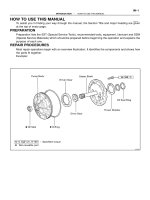
GENERAL INFORMATION
If there is a possiblity that the body and/or parts may be
damaged, first remove the danger before performing repair
operations.
Example:
1. Apply protection tape to the body adjacent to the body part
when removing and installing.
If anti–rust agents are damaged while repairing other parts,
be sure to repair the anti–rust agent.
Example:
1. If body sealer, paint film or undercoat are damaged by
peeling, cracks, etc., be sure to repair each with an antirust
agent.
2. When prying off the body parts with a screwdriver or scrap-
er, etc., be sure to apply protection tape to the tip or blade
to prevent damage to the paint film or body part.
2. If a hinge or exterior body panel is loosened or removed,
be sure to apply rust inhibitor after repairs.
–BODY General Information
BO–2
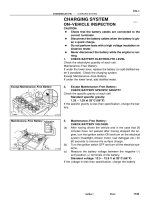
HOOD
ADJUSTMENT OF HOOD
1. ADJUST HOOD IN FORWARD/REARWARD AND
LEFT/RIGHT DIRECTIONS
Adjust the hood by loosening the hood side hinge bolts.
3. ADJUST REAR EDGE OF HOOD IN VERTICAL
DIRECTION
Adjust the hood by increasing or decreasing the number of
the shims.
2. ADJUST FRONT EDGE OF HOOD IN VERTI¿¿L
DIRECTION
Adjust the hood by turning the cushions.
4. ADJUST HOOD LOCK
Adjust the lock by loosening the bolts.
–BODY Hood
BO–3
FRONT DOOR
COMPONENTS
–BODY Front Door
BO–4
3. REMOVE REAR VIEW MIRROR
(a) (Manual type)
Remove the setting screw and knob.
(b) Using a screwdriver, pry loose the retainer and re-
move the cover.
HINT: Tape the screwdriver tip before use.
(c) (Electrical type)
Disconnect the connector.
(d) Remove the three screws–and mirror.
(c) Insert a screwdriver between the retainers and door
trim to pry it loose.
HINT: Tape the screwdriver tip before use.
(d) (w/ Power Window and Power Door Lock)
Disconnect the connectors.
5. REMOVE SERVICE HOLE COVER
6. REMOVE OPENING CONTROL LINK FROM DOOR
LOCK
DISASSEMBLY OF FRONT DOOR
1. REMOVE REGULATOR HANDLE
(w/o POWER WINDOW)
Pull oft the snap ring with a cloth and remove the regulator
handle and plate.
2. REMOVE DOOR INSIDE HANDLE
(a) Remove the screw, and slide the handle forward.
(b) Disconnect the handle from the control link and re-
move the handle.
4. REMOVE DOOR TRIM
(a) Remove the two screws from the armrest.
(b) Remove the two caps and two screws.
–BODY Front Door
BO–5
7. REMOVE DOOR GLASS
(a) Wind the glass down into the door cavity.
(b) Remove the two glass channel mounting nuts.
8. REMOVE WINDOW REGULATOR
(a) (w/ Power Window)
Disconnect the connector.
(b) Remove the regulator mounting bolts.
(e) Remove the equalizer arm bracket mounting bolts.
10. REMOVE REAR LOWER FRAME
11. REMOVE FRONT LOWER FRAME
Remove the two bolts from the panel.
(d) Remove the regulator through the service hole.
9. REMOVE DOOR GLASS RUN
(c) Remove the door glass by pulling it upward.
–BODY Front Door
BO–6
ASSEMBLY OF FRONT DOOR
(See page BO–3)
1. BEFORE INSTALLING PARTS, COAT THEM WITH MIP
GREASE
(a) Coat the sliding surface and gears of the window
regulator with MP grease.
NOTICE: Do not apply MP grease to the spring of the win-
dow regulator.
13. REMOVE DOOR LOCK
(a) Disconnect the links from the door outside handle
and door lock cylinder.
(b) Remove the three screws and the door lock.
(c) (w/ Power Door Lock)
Remove the screw and door lock solenoid.
12. REMOVE FRONT DOOR BELT MOULDING
(a) Remove the screw.
(b) Pry loose the clips from the edge of the panel and re-
move the front door belt moulding.
14. REMOVE DOOR OUTSIDE HANDLE AND DOOR
LOCK CYLINDER
(a) Remove the two bolts and door outside handle.
(b) Remove the clip and door lock cylinder.
(b) Coat the sliding surface of the door lock with IMP
grease.
–BODY Front Door
BO–7
3. INSTALL DOOR LOCK
(a) (w/ Power Door Lock)
Install the door lock solenoid to the door lock with the
screw.
(b) InstalI the door lock with the three screws.
(e) Install the links to the door outside handle and door
lock cylinder.
2. INSTALL DOOR OUTSIDE HANDLE AND DOOR LOCK
CYLINDER
(a) Install the door outside handle with the two bolts.
(b) Install the door lock cylinder with the clip.
4. INSTALL FRONT DOOR BELT MOULDING
(a) Insert the claw of the clips into the upper panel hole
and push the front door belt moulding onto the panel.
(b) Install the screw.
7. INSTALL WINDOW REGULATOR
Place the regulator through the service hole and install the
five mounting bolts.
5. INSTALL FRONT LOWER FRAME
Install the front lower frame with the two bolts.
6. INSTALL REAR LOWER FRAME
–BODY Front Door
BO–8
(b) With the door glass fully closed, .adjust the door glass
stopper so it lightly makes contact with the glass
plate.
11. INSTALL OPENING CONTROL LINK
12. INSTALL SERVICE HOLE COVER
13. INSTALL DOOR TRIM
8. INSTALL DOOR GLASS
(a) Place the glass in the door cavity.
(b) Install the glass to the regulator with the two mount-
ing nuts.
9. INSTALL DOOR GLASS RUN
14. INSTALL REAR VIEW MIRROR
(a) Install the mirror with the three screws.
(b) (Electrical type)
Connect the connector.
(c) Install the cover.
(d) (Manual type)
Install the knob with the setting screw.
15. INSTALL DOOR INSIDE HANDLE
(a) Connect the handle to the control link.
(b) Install the handle, slide it rearward, and install the
screw.
10. ADJUST DOOR GLASS
(a) Adjust the equalizer arm up or down and tighten it
where dimensions A and6, as shown, are equal.
–BODY Front Door
BO–9
3. ADJUST DOOR LOCK STRIKER
(a) Check that the door fit and door lock linkages are ad-
justed correctly.
(b) Adjust the striker position by slightly loosening the
striker mounting screws, and hitting the striker with a
hammer.
Tighten the striker mounting screws again.
ADJUSTMENT OF FRONT DOOR
1. ADJUST DOOR IN FORWARD/REARWARD AND
VERTICAL DIRECTIONS
Using SST, adjust the door by loosening the body side
hinge bolts.
SST 09812–00010
16. INSTALL REGULATOR HANDLE
With door window fully closed, install the plate and regula-
tor handle with a snap ring as shown.
2. ADJUST DOOR IN LEFT/RIGHT AND VERTICAL
DIRECTIONS
Loosen the door side hinge bolts to adjust.
–BODY
BO–10
REAR DOOR
COMPONENTS
–BODY Rear Door
BO–11
(b) Insert a screwdriver between the trim retainers and
the door panel to pry it loose.
HINT: Tape the screwdriver tip before use.
4. REMOVE SERVICE HOLE COVER
5. REMOVE DOOR GLASS RUN
DISASSEMBLY OF REAR DOOR
1. REMOVE REGULATOR HANDLE
(w/o POWER WINDOW)
Pull oft the snap ring with a cloth and remove the regulator
handle and plate.
6. REMOVE DIVISION BAR
(a) Remove the two screws under the weatherstrip.
(b) Remove the bolt.
(c) Pull out the division bar.
2. REMOVE DOOR INSIDE HANDLE
(a) Remove the screw, and slide the handle forward.
(b) Disconnect the control link and remove the handle.
3. REMOVE DOOR TRIM WITH INNER WEATHERSTRIP
(a) Remove the two screws from the armrest.
–BODY Rear Door
BO–12
8. REMOVE WINDOW REGULATOR
(a) (w/ Power Window)
Disconnect the connector.
(b) Remove the regulator –mounting bolts.
(c) Remove the equalizer arm bracket mounting bolts.
7. REMOVE DOOR GLASS
(a) Wind the glass down into the door cavity.
(b) Remove the two glass channel mounting nuts.
9. REMOVE REAR DOOR BELT MOULDING
Pry out the rear door belt moulding with the clip as shown.
(c) Remove the door glass by pulling it upward.
(d) Remove the regulator through the service hole.
–BODY Rear Door
BO–13
12. REMOVE DOOR LOCK
(a) Disconnect the link from the door outside handle.
(b) Remove the three screws and door lock.
(e) (w/ Power Door Lock)
Remove the screw and door lock solenoid.
10. REMOVE INSIDE LOCKING LINK AND KNOB
Remove the bolt and disconnect the link from the door
lock.
11. REMOVE OPENING CONTROL LINK
Disconnect the link from the door lock.
13. REMOVE DOOR OUTSIDE HANDLE
Remove the two bolts and door outside handle.
–BODY Rear Door
BO–14
ASSEMBLY OF REAR DOOR
(See page SO–11)
1. BEFORE INSTALLING PARTS, COAT THEM WITH MP
GREASE
(a) Coat the sliding surface and gears of the window reg-
ulator with MP grease.
NOTICE: Do not apply MP grease to the spring of the win-
dow regulator.
3. INSTALL DOOR LOCK
(a) (w/ Power Door Lock)
Install the door lock solenoid to the door lock with the
screw.
(b) Install the door lock with three screws.
(c) Connect the link to the outside handle.
4. INSTALL OPENING CONTROL LINK
Connect the link to the door lock.
5. INSTALL INSIDE LOCKING LINK AND KNOB
(a) Connect the link to the door lock.
(b) Install the link and knob with the bolt.
(b) Coat the sliding surface of the door lock with MP
grease.
2. INSTALL DOOR OUTSIDE HANDLE
Install the door outside handle with two bolts.
–BODY Rear Door
BO–15
7. INSTALL WINDOW REGULATOR
(a) Place the regulator through the service hole.
(b) Install the five mounting bolts.
(c) (w/ Power Window)
Connect the connector.
6. INSTALL REAR DOOR BELT MOULDING
Insert the claw of the clips into the upper panel hole and
push the rear door belt moulding onto the panel.
8. PLACE DOOR GLASS IN DOOR
(a) Insert the door glass in the door cavity.
(b) Install the regulator into the door glass rail.
(c) Install the two glass channel mounting nuts.
9. ADJUST DOOR GLASS
Adjust the equalizer arm up or down and tighten it where
dimension A and6, as shown, are equal.
(b) With the door glass fully closed, adjust the door
glass, stopper so it lightly makes contact with the
glass plate.
–BODY Rear Door
BO–16
10. INSTALL DIVISION BAR
(a) Place the division bar in the door.
(b) Install the two screws and bolt.
11. INSTALL DOOR GLASS RUN
12. INSTALL SERVICE HOLE COVER
13. INSTALL DOOR TRIM WITH INNER WEATHERSTRIP
14. INSTALL DOOR INSIDE HANDLE
(a) Connect the handle to the control link.
(b) Install the handle, slide it rearward, and install the
screw.
15. INSTALL REGULATOR HANDLE
With the door window fully closed, install the plate and
regulator handle with the snap ring as shown.
–BODY Rear Door
BO–17
3. ADJUST DOOR LOCK STRIKER
(a) Check that the door fit and lock linkages are adjusted
correctly.
(b) Adjust the striker position by slightly loosening the
striker mounting screws, and hitting the striker with a
hammer.
Tighten the striker mounting screws again.
ADJUSTMENT OF REAR DOOR
1. ADJUST DOOR IN FORWARD/ REARWARD AND
VERTICAL DIRECTIONS
Using a wrench, loosen the body side hinge bolts.
2. ADJUST DOOR IN LEFT/RIGHTAND VERTICAL
DIRECTIONS
Using a wrench, loosen the door side hinge bolts.
–BODY Rear Door
BO–18
LUGGAGE COMPARTMENT LID
REMOVAL OF TORSION BAR
REMOVE TORSION BAR FROM LUGGAGE
COMPARTMENT LID HINGE
(a) Install SST to the torsion bar on the hinge side.
SST 09804–24010
INSTALLATION OF TORSION BAR
INSTALL TORSION BAR TO LUGGAGE COMPARTMENT
LID HINGE
(a) Insert the torsion bar into the bracket as shown.
(b) Connect the torsion bar to the center bracket.
(c) Slowly lift SST, and remove the torsion bar from the
torsion bar bracket with SST.
(d) Remove the torsion bar from the center bracket.
(e) Do the same for the other side.
(c) Install SST to the torsion bar of the hinge side.
SST 09804–24010
(d) Slowly lift the torsion bar with SST and place on the tor-
sion bar bracket.
(b) Push down on SST, and pull the luggage compart-
ment lid hinge from the torsion bar.
–BODY Luggage Compartment Lid
BO–19
ADJUSTMENT OF LUGGAGE
COMPARTMENT LID
(a) Forward/rearward and left/right adjustments loos-
en the bolts.
(b) For vertical adjustment of front end of lid, increase
or decrease the number of washers.
ADJUSTMENT OF LOCK STRIKER
(a) Loosen the mounting bolts.
(b) Using a brass bar and hammer, tap the striker to ad-
just it.
(e) Slowly pushdown SST, and install the torsion bar to
the luggage compartment !id hinge.
(f) Slowly lift SST, and install the torsion bar.
Do the same for the other side.
–BODY Luggage Compartment Lid
BO–20
BACK DOOR
COMPONENTS
–BODY Back Door
BO–21
3. REMOVE DOOR LOCK CONTROL
(a) Remove the link protector.
(b) Disconnect the links from the door lock control and
door lock cylinder.
(c) Disconnect the connector from the solenoid.
(d) Remove the four bolts and door lock control with the
solenoid.
DISASSEMBLY OF BACK DOOR
1. REMOVE UPPER AND LOWER DOOR TRIMS
(a) Remove the six clips.
(b) Insert a screwdriver between the trim retainers and
door panel to pry it loose.
HINT: Tape the screwdriver tip before use.
2. REMOVE HIGH MOUNT STOP LIGHT
(a) Disconnect the connector from the high mount stop
light.
(b) Remove the two bolts and high mount stop light.
4. REMOVE DOOR LOCK CYLINDER
Remove the two screws and door lock cylinder.
5. REMOVE LOWER MOULDING
(See page 80–36)
6. REMOVE COMBINATION LIGHT
(a) Disconnect the connector from the combination light.
(b) Remove the eight nuts and combination light.
–BODY Back Door
BO–22
ASSEMBLY OF BACK DOOR
(See page 80–21)
INSTALL BACK DOOR PARTS BY FOLLOWING
DISASSEMBLY SEQUENCE IN REVERSE
7. REMOVE BACK DOOR GARNISH
Remove the five nuts, nine clips and back door garnish.
8. REMOVE OUTSIDE HANDLE
Remove the three screws and outside handle.
9. REMOVE DOOR LOCK
Remove the three bolts and door lock.
–BODY Back Door
BO–23
Back Door Damper Stay
NOTICE: Handling the damper. .
(a) Do not disassemble the damper because the cylinder
is filled with pressurized gas.
(b) If the damper is to be replaced, drill a 2.0 – 3.0ttm
(0.079 – 0.118 in.) hole in the bottom of the removed
damper cylinder to completely release the
high–pressure gas before disposing of it.
(c) When drilling, chips may fly out, so work carefully.
(d) The gas is colorless, odorless and non poisonous.
(e) When working, handle the damper carefully. Never
score or scratch the exposed part of the piston rod,
and never allow paint or oil to get on it.
(f) Do not turn the piston rod and cylinder with the damp-
er fully extended.
REMOVAL OF DAMPER STAY
1. REMOVE DAMPER STAY UPPER END FROM BACK
DOOR
2. REMOVE DAMPER STAY LOWER END FROM BODY
INSTALLATION OF DAMPER STAY
1. INSTALL DAMPER STAY UPPER END TO BACK DOOR
2. CONNECT DAMPER STAY LOWER END TO BODY
ADJUSTMENT OF BACK DOOR
1. ADJUST DOOR IN FORWARD/REARWARD AND
LEFT/RIGHT DIRECTIONS
Adjust the door by loosening the hinge bolts.
2. ADJUST DOOR LOCK STRIKER
(a) Loosen the mounting bolts.
(b) Using a plastic hammer, tap the striker to adjust it.
–BODY Back Door
BO–24
1. REMOVE SIDE MOULDING
(a) Insert the top of a scraper between the body and
moulding. .
(b) Pry up the scraper to loosen the moulding from the
claws of the clips and fasteners.
HINT: Apply tape to the scraper blade to prevent scratching
the vehicle body.
(c) Remove the moulding.
MOULDING
Windshield Outside Moulding
COMPONENTS
REMOVAL OF OUTSIDE MOULDING
Locations of clips and fasteners are as shown. Carefully
apply adhesive tape to protect the body.
–BODY Moulding
BO–25