Camry Repair Manual Body electrical
Bạn đang xem bản rút gọn của tài liệu. Xem và tải ngay bản đầy đủ của tài liệu tại đây (3.82 MB, 104 trang )
BODY ELECTRICAL SYSTEM
–BODY ELECTRICAL SYSTEM
BE–1
GENERAL INFORMATION
WIRING COLOR CODE
Wire colors are indicated by an alphabetical code.
B =Black L =Blue R =Red
BR=Brown LG=Light Green V =Violet
G =Green O =Orange W=White
GR=Gray P =Pink Y =Yellow
The first letter indicates the basic wire color and the sec–
ond letter indicates the color of the stripe.
CONNECTOR
1. PIN NUMBER OF FEMALE CONNECTOR
Numbered in order from upper left to lower right.
2. PIN NUMBER OF MALE CONNECTOR
Numbered in order from upper right to lower left.
3. DISTINCTION OF MALE AND FEMALE CONNECTORS
Male and female connectors are distinguished by shape
of their internal pins.
(a) All connectors are shown from the open end, and the
lock is on top.
(b) To pull apart the connectors, pull on the connector it-
self, not the wires.
HINT: Check the type of connector before disconnecting.
–BODY ELECTRICAL SYSTEM General information
BE–2
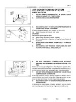
RESET CIRCUIT BREAKER
1. REMOVE CIRCUIT BREAKER
(a) Disconnect the negative (–) cable from the battery.
(b) Remove the circuit breaker.
2. RESET CIRCUIT BREAKER
(a) Insert the needle into the reset hole and push it.
3. INSTALL CIRCUIT BREAKER
(a) Install the circuit breaker.
(b) Connect the negative (–) cable to the battery.
HINT: If a circuit breaker continues to cut out, a short circuit
is indicated. Have the system checked by a qualified tec
nician.
REPLACEMENT OF FUSE AND
FUSIBLE LINK
HINT: If replacing the fuse or fusible link, be sure to
replace it with a fuse or fusible link with an equal amperage
rating.
(b) Using an ohmmeter, check that there is continuity be-
tween both terminals of the circuit breaker.
If continuity is not as specified, replace the circuit breaker.
HINT: If replacing the circuit breaker, be sure to replace
it with a breaker with an equal amperage, rating.
–BODY ELECTRICAL SYSTEM General Information
BE–3
NOTICE:
1. Turn off all electrical components and the ignition
switch before replacing a fuse or fusible link. Do not
exceed the fuse or fusible link amperage rating.
2. Always use a fuse puller for removing and inserting
a fuse. Remove and insert straight in and out without
twisting. Twisting could force open the terminals too
much, resulting in a bad connection.
If a fuse or fusible link continues to blow, a short circuit is
indicated. The system must be checked by a qualified tech-
nician.
–BODY ELECTRICAL SYSTEM General information
BE–4
If the circuit has diodes, reverse the two leads and check
again.
When contacting the negative (–) lead to the diode positive
(+)
side and the positive (+) lead to the negative (–) side, there
should be continuity.
When contacting the two leads in reverse, there should be
no continuity.
HINT: Specifications may vary depending on the type of
tester, so refer to the tester’s instruction manual before per-
forming the inspection.
Check LED (Light Emitting Diode) in the same manner as
that for diodes.
HINT:
• Use a tester with a power source of 3 V or greater to over-
come the circuit resistance.
• If a suitable tester is not available, apply voltage and check
that the LED lights up.
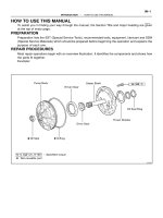
CHECK FOR VOLTAGE
(a) Establish conditions in which voltage is present at
the check point.
Example:
(A) – Ignition SW on
(B) – Ignition SW and SW 1 on
(C) – Ignition SW, SW 1, and Relay on (SW 2 off)
(b) Using a voltmeter, connect the negative (–) lead to
a good ground point or negative (–) battery terminal
and the positive (+) lead to the connector or compo-
nent terminal. This check can be done with a test
bulb instead of a voltmeter.
CHECK FOR CONTINUITY AND
RESISTANCE
(a) Disconnect the battery terminal or wire so there is
no voltage between the check points.
(b) Contact the two leads of an ohmmeter to each of
the check points.
–BODY ELECTRICAL SYSTEM General Information
BE–5
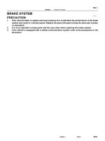
CHECK FOR SHORT CIRCUIT
(a) Remove the blown fuse and eliminate all toads from
the fuse.
(b) Connect a test bulb in place of the fuse.
(e) Establish conditions in which the test bulb comes on.
Example:
(A) – Ignition SW on
(B) – Ignition SW and SW 1 on
(C) – Ignition SW, SW 1 and Relay on (Connect the
Relay) and SW 2 oft (or Disconnect SW 2)
(d) Disconnect and reconnect the connectors while
watching the test bulb.
The short lies between the connector where the test
bulb stays lit and the connector where the bulb goes
out.
(e) Find the exact location of the short by lightly shaking
the problem wire along the body.
(c) Use a volt/ohmmeter with high impedance (10 k
W/V
minimum) for troubleshooting of the electrical circuit.
–BODY ELECTRICAL SYSTEM General Information
BE–6
LOCATION OF SWITCHES AND
RELAYS
–BODY ELECTRICAL SYSTEM Location of Switches and Relays
BE–7
LOCATION OF SWITCHES AND
RELAYS (Cont’d)
–BODY ELECTRICAL SYSTEM Location of Switches and Relays
BE–8
LOCATION OF SWITCHES AND
RELAYS (Cont’d)
–BODY ELECTRICAL SYSTEM Location of Switches and Relays
BE–9
LOCATION OF SWITCHES AND
RELAYS (Cont’d)
–BODY ELECTRICAL SYSTEM Location of Switches and Relays
BE–10
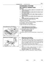
Fuses
1. GAUGE
2. –
3. STOP
4. TAIL
5. CIG
6. RADIO
7. TURN
8. DEF–I/UP
9. –
10. ENGINE
11. WIPER
12. ECU–IG
13. –
14. IGN
15. ECU–B
FUSE AND RELAY BLOCK No–1 (LOCATION: Driver’s Side Kick Panel)
7.5A
20A
15A
15A
7.5A
7.5A
10A
10A
20A
15A
7.5A
1 0A
FUSE AND RELAY BLOCKS
–BODY ELECTRICAL SYSTEM Location of Switches and Relays
BE–11
Fuses
1. HEAD–HI (RH) 15A (CANADA)
2. HEAD–HI (LH) 15A (CANADA)
3. DOME 20A
4. – –
5. HEAD (RH) 15A (USA)
HEAD–LO (RH) 15A (CANADA)
6. CHARGE 7.5A
7. ER 15A
8. HAZ.HORN 15A
9. HEAD (LH) 15A (USA)
HEAD–LO (H) 15A (CANADA)
Relays
A. A/C FAN No.3 Relay
B. A/C MAGNET CLUTCH Relay
(USA)
DIMMER Relay (CANADA)
C. A/C FAN No.2 Relay
D. FAN No. 1 Relay
E. HEADLIGHT Relay
F. EFI MAIN Relay
G. ENGINE MAIN Relay
FUSE AND RELAY BLOCK No–2 (LOCATION: Engine Compartment)
FUSE AND RELAY BLOCKS (Cont’d)
–BODY ELECTRICAL SYSTEM Location of Switches and Relays
BE–12
IGNITION SWITCH AND UNLOCK
WARNING SWITCH
INSPECTION OF SWITCHES
INSPECT SWITCHES CONTINUITY
Inspect the switch continuity between terminals.
Ignition switch
If continuity is not as specified, replace the
switch.
Released (Remove ignition key)
Pushed in (Set ignition key)
Unlock warning switch
Switch pin position
Switch position
Terminal
Terminal
START
LOCK
ACC
–BODY ELECTRICAL SYSTEM Ignition Switch and Unlock Warning Switch
BE–13
Fusible link blown
Headlight control relay faulty
Light control/dimmer switch faulty
Daytime running light relay faulty
(CANADA)
Headlight dimmer relay faulty
(CANADA)
Wiring or ground faulty
Replace fuse and check for short
Replace fusible fink
Check relay
Check switch
Check relay
Repair as necessary
TAIL fuse blown
Fusible link blown
Taillight control relay faulty
Light control switch faulty
Daytime running light relay faulty
(CANADA)
Wiring or ground faulty
Light control/dimmer switch faulty
Daytime running light relay faulty
(CANADA)
Headlight dimmer relay faulty
(CANADA)
Wiring or ground faulty
Replace fusible link
Check relay
Check switch
Check relay
Check relay
Repair as necessary
Replace fuse and check for short
Check flasher
Check switch
Repair as necessary
Replace fuse and check short
Check flasher
Check switch
Repair as necessary
HAZ–HORN fuse blown
Turn signal flasher faulty
Hazard warning switch faulty
Wiring or ground faulty
Check switch
Check relay
Check relay
Repair as necessary
Replace fuse and check for short
Adjust or replace switch
Repair as necessary
TURN fuse blown
Turn signal flasher faulty
Turn signal switch faulty
Wiring or ground faulty
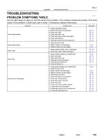
LIGHTING
Troubleshooting
STOP fuse blown
Stop light swtich faulty
Wiring or ground faulty
Light bulb burned out
Socket, wire or ground faulty
High beam headlights or
headlight flashers do not
operate
Light control rheostat faulty
Wiring or ground faulty
Instrument lights do not
light (taillights light)
Tail, parking and
license light do not
light
Turn signal switch faulty
Wiring or ground faulty
Hazard warning lights do
not operate
Replace bulb
Repair as necessary
Headlights do not light
Check switch
Repair as necessary
Check rheostat
Repair as necessary
Only one light comes
ON
Turn signal does not
flash on one side
Turn signals do not
operate
BE–3
BE–3
BE–18
BE–15
BE–25
Adjust or replace switch
Stop light switch faulty
BE–3
BE–18
BE–15
BE–25
Stop lights do not light
Stop lights stay on
BE–3
BE–19
BE–19
BE–3
BE–19
BE–15
Possible cause
BE–15
BE–25
BE–3
BE–89
Remedy
Problem
BE–15
BE–23
BE–89
BE–25
BE–25
Page
–BODY ELECTRICAL SYSTEM Lighting
BE–14
Light Control Switch, Headlight
Dimmer Switch and Turn Signal
Switch
INSPECTION OF SWITCHES
INSPECT SWITCHES CONTINUITY
Inspect the switch continuity between terminals.
Light control switch
If continuity is not as specified, replace the
switch.
Headlight dimmer switch
Turn signal switch
Switch position
Switch position
Switch position
High Beam
Right Turn
Low Beam
Terminal
Terminal
Terminal
Left Turn
Neutral
HEAD
Flash
TAIL
OFF
–BODY ELECTRICAL SYSTEM Lighting
BE–15
2. REMOVE CONTROL LEVER
(a) Remove the bail set plate and the ball.
(b) Remove the control lever with the spring.
3. REMOVE SWITCHES
Remove the switches with the four screws.
4. INSTALL SWITCHES
(b) From the open end, insert a miniature screwdriver
between the locking lug and the terminal.
(c) Pry down the locking lug with the screwdriver and
pull the terminal out from the rear.
5. INSTALL CONTROL LEVER
(a) Insert the spring into the control lever and install the
control lever.
1. REMOVE TERMINALS FROM CONNECTOR
(a) Release the four tabs and open the terminal cover.
REPLACEMENT OF SWITCHES
–BODY ELECTRICAL SYSTEM Lighting
BE–16
7. INSTALL TERMINALS TO CONNECTOR
(a) Push in the terminal until it is securely locked in the
connector lug.
(b) Close the terminal cover.
(b) Place the ball on the spring, position the control lever
at HIGH and install the ball set plate with the two
screws.
6. INSPECT SWITCH OPERATION
Insure that the switch operates smoothly.
–BODY ELECTRICAL SYSTEM Lighting
BE–17
Taillight Control Relay
INSPECTION OF RELAY
1. INSPECT RELAY CONTINUITY
(a) Check that there is continuity between terminals 1
and 3.
(b) Check that there is no continuity between terminals
2 and 4.
(e) Check that there is no continuity between terminals
3 and 4.
If continuity is not as specified, replace the relay.
Headlight Control Relay
INSPECTION OF RELAY
1. INSPECT RELAY CONTINUITY
(a) Check that there is continuity between terminals 1
and 2.
(b) Check that there is no continuity between terminals
3 and 4.
(e) Check that there is no continuity between terminals
1 and 4.
If continuity is not as specified, replace the relay.
2. INSPECT RELAY OPERATION
(a) Apply battery voltage to terminals 1 and 2.
(b) Check that there is continuity between terminals 3
and 4.
(c) Check that there is no continuity between terminals
1 and 4.
If operation is not as specified, replace the relay.
–BODY ELECTRICAL SYSTEM Lighting
BE–18
Turn Signal Flasher
INSPECTION OF FLASHER
INSPECT FLASHER OPERATION
(a) Connect the positive (+) lead from the battery to
terminal 3 and the negative (–) lead to terminal 2.
(b) Connect the two turn signal light bulbs parallel to each
other to terminals 1 and 2, check that the bulbs turn
on and off.
HINT: The turn signal lights should flash 60 to 120 times per
minute.
If one of the front or rear turn signal lights has an open cir–
cuit, the number of flashes will be more than 140 per mi
ute.
If operation is not as specified, replace the flashes.
2. INSPECT RELAY OPERATION
(a) Apply battery voltage to terminals 1 and 3.
(b) Check that there is continuity between terminals 2
and 4.
(c) Check that there is no continuity between terminals
3 and 4.
If operation is not as specified, replace the relay.
Hazard Warning Switch
INSPECTION OF SWITCH
INSPECT SWITCH CONTINUITY
Inspect the switch continuity between terminals.
If continuity is not as specified, replace the switch or
bulb.
Switch position
OFF (Free)
ON (Lock)
Terminal
0)
c
o
N
t
o
(71
–BODY ELECTRICAL SYSTEM Lighting
BE–19
Taillight Failure Sensor
INSPECTION OF SENSOR
1. INSPECT WARNING LIGHT OPERATION
(a) Disconnect the connector from the failure sensor and
ground the terminal 3 on the wire harness side.
(b) Remove the CHARGE fuse and turn the ignition
switch ON, check that the bulb lights.
If bulb does not light, inspect the bulb.
2. INSPECT SENSOR CIRCUIT
Disconnect the failure sensor connector and inspect the
connector on the wire harness side as shown in the chart.
If circuit is as specified, replace the relay.
Stop light switch ON (Brake pedal depressed)
Stop light switch OFF (Brake pedal released)
Turn light control switch TAIL or HEAD
Turn ignition switch to OFF or ACC
Turn ignition switch to OFF or ACC
Turn light control switch OFF
Turn ignition switch ON
Remove CHARGE fuse
Turn ignition
switch ON
Install CHARGE fuse
Tester
connection
Specified value
Battery voltage
Battery voltage
Battery voltage
Battery voltage
No voltage
Continuity
No voltage
Continuity
No vottage
No voltage
Continuity
Continuity
No voltage
Continuity
Continuity
Condition
Check for
Voltage
Voltage
Voltage
Always
Always
Always
–BODY ELECTRICAL SYSTEM Lighting
BE–20
Integration Relay
INSPECTION OF RELAY
INSPECT RELAY CIRCUIT
Disconnect the relay connector and inspect the connector
on the wire harness side as shown in the chart.
Passenger’s side and rear door courtesy switches OFF
(Door closed)
Passenger’s side or rear door courtesy switch ON
(Door opened)
Turn headlight dimmer switch to low beam or high beam
Driver’s side door courtesy switch ON (Door opened)
Driver’s side door courtesy switch OFF (Door closed)
Turn light control switch to OFF or TAIL
Turn light control switch TAIL or HEAD
Turn headlight dimmer switch to Flash
Turn ignition switch to OFF or ACC
Turn light control switch to HEAD
Turn light control switch OFF
(w/o Fade Out System)
Turn ignition switch ON
Tester
connection
Specified value
Battery voltage
Battery voltage
Battery voltage
Battery voltage
Battery voltage
No continuity
No continuity
No continuity
Condition
No voltage
Continuity
No voltage
No voltage
Continuity
Continuity
Continuity
Continuity
Continuity
Check for
Voltage
Voltage
Voltage
Always
Always
–BODY ELECTRICAL SYSTEM Lighting
BE–21
Room Light Retainer Switch
INSPECTION OF SWITCH
INSPECT SWITCH CONTINUITY
(a) Check that there is no continuity between terminals
with the switch OFF (Door outside handle released).
(b) Check that there is continuity between terminals with
the switch ON (Door outside handle pulled).
If continuity is not as specified, replace the switch.
Passenger’s side and rear door courtesy switches OFF
(Door closed)
Passenger’s side or rear door courtesy switch ON
(Door opened)
Door room light retainer switch ON
(Door outside handle pulled up on driver’s side)
Door room light retainer switch OFF
(Door outside handle released on driver’s side)
Turn headlight dimmer switch to low beam or high beam
Driver’s side door courtesy switch ON (Door opened)
Driver’s side door courtesy switch OFF (Door closed)
If circuit is as specified, replace the relay.
Turn light control switch to OFF or TAIL
Turn light control switch TAIL or HEAD
Turn headlight dimmer switch to Flash
Turn ignition switch to OFF or ACC
Turn light control switch to HEAD
Turn light control switch OFF
(w/ Fade Out System)
Condition
Turn ignition switch ON
Tester
connection
Specified value
Battery voltage
Battery voltage
Battery voltage
Battery voltage
Battery voltage
Battery voltage
No continuity
No continuity
No continuity
No continuity
No voltage
No voltage
No voltage
Continuity
Continuity
Continuity
Continuity
Continuity
Continuity
Continuity
Continuity
Continuity
Always .
Check for
Voltage
Voltage
Voltage
Voltage
Always
Always
Always
–BODY ELECTRICAL SYSTEM Lighting
BE–22
Current is led from the battery to terminal 12 of the running light relay.
Operation examples of the switch are shown below.
1. IGNITION SWITCH ”ON” AND LIGHT CONTROL SWITCH ”OFF”
When the switches are set, current is led from the battery to terminal 1 of the running light relay. Also,
because continuity is made between terminal 3 and the body ground, and 5 and the body ground of
the running light relay, the taillight control relay and headlight control relay are turned on.
Then the taillights and headlights light up.
HINT: Because terminal 14 of the running light relay is not grounded at all times, the headlight dimmer
relay is off, so that the headlights light up at the low beam.
2. LIGHT CONTROL SWITCH IN ”HEAD”
When the switch is set, continuity is made between terminal 4 and the body ground, and 2 and the body
ground of the running light relay. Also, because the continuity is made between terminal 5 and the body
ground, and 3 and the body ground of the running light relay at all times, the taillights and headlights
light up.
HINT: When the headlight dimmer switch is set to ”HIGH”, continuity is made between terminal 13 of
the running light relay and the body ground. Also, because continuity is made between terminal 14 of
the running light relay and the body ground, the headlight dimmer relay is turned on. Then the head-
lights go on at the high beam.
3. HEADLIGHT DIMMER SWITCH IN ”FLASH”
When the switch is set, continuity is made between terminal 6 and the body ground, and 13 and the
body ground of the running light relay. Also, because the continuity is made between terminal 5 and
the body ground, and 14 and the body ground of the running light relay, the headlights flash.
4. ENGINE STOPS (IGNITION SWITCH ”ON”)
When the engine is stopped, because the continuity between terminal 5 and terminal 10 of the running
light relay remains, so the running lights also remain.
HINT: If ignition switch is turned to ”OFF”, running lights will go off because the continuity between termi-
nal 5 and terminal 10 of the running light relay is cut off.
Light Control Rheostat
INSPECTION OF RHEOSTAT
INSPECT RHEOSTAT OPERATION
(a) Connect the positive (+) lead from the battery to
terminal 1 and the negative (–) lead to terminal 2.
(b) Connect the terminals 1 and 3 through a 3.4 W test bulb.
(c) Gradually turn the rheostat knob from the bright side to
dark side, check that the test bulb brightness changes
from bright to dark.
If operation is not as specified, replace the rheostat.
Daytime Running Light System
(CANADA)
DESCRIPTION
–BODY ELECTRICAL SYSTEM Lighting
BE–23
WIRING AND CONNECTOR DIAGRAMS
• Dimmer Switch
• Light Control
Switch
• Turn Signal Switch
Daytime Running Light Relay
Taillight Control Relay
Headlight
Control Rela
Integration Relay
Ignition Switch
Dimmer Relay
–BODY ELECTRICAL SYSTEM Lighting
BE–24
(Relay Operation)
(a) Connect the positive (+) lead from the voltmeter to ter-
minal 7 and negative (–) lead to terminal 10.
(b) Check that there is battery voltage with light control
switch is turned on.
If operation is not as specified, replace the relay.
If continuity is not as specified, replace the relay.
2. INSPECT DAYTIME RUNNING LIGHT RELAY
(Relay Circuit)
Disconnect the connector from the relay and inspect the
connector on the wire harness side as shown in the chart.
INSPECTION OF RELAY
1. INSPECT DIMMER RELAY (Continuity)
If circuit is as specified, inspect relay operation.
Apply battery voltage to
terminals 2 and 4.
Light control switch
position
Light control switch
position
Headlight dimmer
switch position
Headlight dimmer
switch position
Low beam or High beam
Ignition switch
position
7 – Ground
10 – Ground
High beam or Flash
13 – Ground
3 – Ground
5 – Ground
Tester connection
Ground terminal 5
Specified value
Battery voltage
Battery voltage
Battery voltage
Battery voltage
Battery voltage
No continuity
No continuity
TAIL or HEAD
No continuity
No continuity
14 – Ground
12 – Ground
ON or START
LOCK or ACC
1 – Ground
OFF or TAIL
8 – Ground
2 – Ground
6 – Ground
4 – Ground
No voltage
No voltage
No voltage
Continuity
Continuity
Continuity
Continuity
Continuity
Continuity
Condition
Check for
Low beam
Condition
Running
Terminal
Constant
Constant
Constant
Constant
Constant
Voltage
Engine
HEAD
Flash
Stop
OFF
–BODY ELECTRICAL SYSTEM Lighting
BE–25