Camry Repair Manual Maintenance
Bạn đang xem bản rút gọn của tài liệu. Xem và tải ngay bản đầy đủ của tài liệu tại đây (595.27 KB, 17 trang )
MAINTENANCE
–MAINTENANCE
MA–1
Maintenance services indicated by a star (*) or asterisk (*) are required under the terms of the Emission Control Systems Warranty. See Owner’s Guide or Warranty Booklet
for complete warranty information.
* For vehicles sold in California
* For vehicles sold outside California
(1) Applicable to vehicles operated under conditions of extensive idling and /or low speed driving for long distances such as police, taxi or door–to–door delivery use.
(2) Applicable when operating mainly on dusty roads. If not, follow SCHEDULE B.
(3) Includes inspection of fuel tank band and vapor vent system.
(4) Also applicable to lining drum for parking brake.
(5) Check for leakage.
(6) Check for oil leaks from steering gear housing.
(7) Applicable only when operating mainly on rough, muddy roads. The applicable parts are listed below. For other usage conditions, refer to SCHEDULE B.
• Front and rear suspension member to body
• 0 Strut bar bracket to body bolts
• Bolts for sheet installation
MAINTENANCE SCHEDULE
SCHEDULE A
CONDITIONS:
• Towing a trailer, using a camper or car top carrier.
• Repeated short trips less than 5 miles (8 km) and outside temperatures remain below freezing.
• Extensive idling and/or low speed driving for a long distance such as police, taxi or door–to–door delivery use.
• Operating on dusty, rough, muddy or salt spread roads.
Maintenance operations: A = Check and adjust if necessary;
R = Replace, change or lubricate;
I = Inspect and correct or replace if necessary
Maintenance services beyond 60,000 miles (96,000 km) should continue to be performed at the same intervals shown for each
maintenance schedule.
Service interval
(Odometer reading or
months, whichever
comes first)
Maintenance items
Manual transaxle, automatic transaxle
and differential
Brake pads and discs (Front and rear)
Bolts and nuts on chassis and body
Exhaust pipes and mountings
Steering gear housing oily
Brake line pipes and hoses
Fuel lines and connections
Ball joints and dust covers
Engine oil and oil filter
Spark plugs (platinum tipped)
MA–4 (item 2)
MA–6 (item 6)
Brake linings and drums
Fuel tank cap gasket
Drive shaft boots
MA–14 item 221
MA–10 (item 20)
MA–5 (item 3,4)
Steering linkage
MA–7 (item 12)
MA–8 (item 14)
Valve clearance
MA–8 (item 16)
MA–9 (item 19)
MA–7 (item 13)
MA–7 (item 11
MA–7 (item 10)
MA–9 (item 18)
Charcoal canister
MA–9 (item 17)
MA–8 (item 151
See page
(item No.)
Engine coolant
MA–6 (item 9)
MA–4 (item 1)
MA–4 (item 2)
MA–5 (item 5)
MA–8 (item 8)
AAA–6 (item 7)
Air filter¿21*
Spark plugs
Timing belt
Drive belts
IGNITION
CHASSIS
BRAKES
ENGINE
System
EVAP
FUEL
–MAINTENANCE Maintenance Schedule
MA–2
Maintenance services indicated by a star (*) or asterisk (*) are required under the terms of the Emission Control Systems Warranty.
See Owner’s Guide or Warranty
Booklet for complete warranty information.
E For vehicles sold in California
* For vehicles sold outside California
(1) Includes inspection of fuel tank band and vapor vent system.
(2) Also applicable to drum lining for parking brake.
(3) Check for leakage.
(4) Check for oil leaks from steering gear housing.
(5) The applicable part are listed below
• Front and rear suspension member to body
• Strut bar bracket to body bolts
• Bolts for sheet installation
Maintenance service beyond 60,000 miles (96,000 km) should continue to be performed at the same intervals shown
for each maintenance schedule.
SCHEDULE B
CONDITIONS: Conditions other than those listed for SCHEDULE A.
Service interval
(Odometer reading or
months, whichever
comes first)
Maintenance items
Manual transaxle, automatic
transaxle and differential (3)
Brake pads and discs (Front and rear
Bolts and nuts on chassis and body 17)
Exhaust pipes and mountings
Steering gear housing oil 1s)
Brake linings and drums (4)
Brake line pipes and hoses
Fuel lines and connections (31
Ball joints and dust covers
Engine oil and oil filter
Spark plugs (platinum tipped
Fuel tank cap gasket
MA–14 (item 22)
MA–10 (item 20)
Charcoal canister
Steering linkage
Drive shaft boots
MA–7 (item 11)
MA–9 (item 19)
MA–9 (item 18)
MA–7 (item 13)
MA–7 (item 10)
MA–8 (item 14)
MA–7 (item 12)
MA–8 (item 16)
MA–8 (item 15)
See page
(item No.)
Engine coolant
MA–9 (item 17)
Valve clearance
MA–6 (item 8)
MA–4 (item 2)
MA–6 (item 9)
MA–6 (item 7)
MA–6 (item 7)
MA–5 (item 5)
MA–5 (item 4)
Drive belts
Air filter
Spark plugs
IGNITION
CHASSIS
BRAKES
ENGINE
System
EVAP
FUEL
–MAINTENANCE Maintenance Schedule
MA–3
GENERAL MAINTENANCE
These are the maintenance and inspection items
which are considered to be the owner’s responsibility,
They can be performed by the owner or he
can have then done at a service shop. These items
include those which should be checked on a daily ba-
sis, those which, in most cases, do not require
(special) tools and those which are considered to be
reasonable for the owner to perform.
Items and procedures for general maintenance are as
follows:
OUTSIDE VEHICLE
1. TIRES
(a) Check the pressure with a gauge. Adjust
if necessary.
(b) Check for cuts, damage or excessive wear.
2. WHEEL NUTS
When checking the tires, check the nuts for looseness
or for missing nuts. If necessary,
tighten them.
3. TIRE ROTATION
It is recommended that tires be rotated every
7,500 miles (12,000 km).
4. WINDSHIELD WIPER BLADES
Check for wear or cracks whenever they do not wipe
clean. Replace if necessary.
5. FLUID LEAKS
(a) Check underneath for leaking fuel, oil, water or
other fluid.
(b) If you smell gasoline fumes or notice any leak,
have the cause found and corrected.
6. DOORS AND ENGINE HOOD
(a) Check that all doors including the trunk lid and
back door operate smoothly, and that all
latches lock securely.
(b) Check that the engine hood secondary latch se-
cures the hood from opening when the prima-
ry latch is released.
INSIDE VEHICLE
7. LIGHTS
(a) Check that the headlights, stop lights, taillights,
turn signal lights, and other
lights are all working.
(b) Check the headlight aiming.
8. WARNING LIGHTS AND BUZZERS
Check that all warning lights and buzzers func-
tion properly.
9. HORN
Check that it is working.
10. WINDSHIELD GLASS
Check for scratches, pits or abrasions.
11. WINDSHIELD WIPER AND WASHER
(a) Check operation of the wipers and washer.
(b) Check that the wipers do not streak.
12. WINDSHIELD DEFROSTER
Check that air comes out from the defroster out-
let when operating the heater or air conditioner
at defroster mode.
13. REAR VIEW MIRROR
Check that it is mounted securely.
14. SUN VISORS
Check that they move freely and are mounted
securely.
15. STEERING WHEEL
Check that it has the specified freeplay. Be alert
for changes in steering condition, such as hard
steering, excessive freeplay or strange noise.
16. SEATS
(a) Check that all front seat controls such as
seat adjusters, seatback recliner, etc.
operate smoothly.
(b) Check that a11 latches lock securely in
any position.
(c) Check that the locks hold securely in any
latched position.
(d) Check that the head restraints move up
and down smoothly and that the locks
hold securely in any latched position.
(e) For folding–down rear seat backs, check
that the latches lock securely.
17. SEAT BELTS
(a) Check that the seat belt system such as
buckles, retractors and anchors operate
properly and smoothly.
(b) Check that the belt webbing is not cut,
frayed, worn or damaged.
–MAINTENANCE General Maintenance
MA–16
18. ACCELERATOR PEDAL
Check the pedal for smooth operation and uneven
pedal effort or catching.
19. CLUTCH PEDAL (See page CL–3)
Check the pedal for smooth operation.
Check that the pedal has the proper freeplay.
20. BRAKE PEDAL (See page BR–6)
(a) Check the pedal for smooth operation.
(b) Check that the pedal has the proper reserve
distance and freeplay.
(c) Check the brake booster function.
21. BRAKES
At a safe place, check that the brakes do not pull
to one side when applied.
22. PARKING BRAKE (See page BR–8)
(a) Check that the lever has the proper travel.
(b) On a safe incline, check that the vehicle is
held securely with only the parking brake
applied.
23. AUTOMATIC TRANSMISSION PARK
MECHANISM
(a) Check the lock release button of the selector
lever for proper and smooth operation.
(b) On a safe incline, check that vehicle is held
securely with the selector lever in the ”P”
position and all brakes released.
UNDER HOOD
24. WINDSHIELD WASHER FLUID
Check that there is sufficient fluid in the tank.
25. ENGINE COOLANT LEVEL
Check that the coolant level is between the
”FULL” and ”LOW” lines on the see–through reser-
voir.
26. RADIATOR AND HOSES
(a) Check that the front of the radiator is clean
and not blocked with leaves, dirt or bugs.
(b) Check the hoses for cracks, kinks, rot or
loose connections.
27. BATTERY ELECTROLYTE LEVEL
Check that the electrolyte level of all battery cells
is between the upper and lower level lines on the
case. If level is low, add distilled water only.
28. BRAKE AND CLUTCH FLUID LEVELS
(a) Check that the brake fluid level is near the
upper level line on the see–through reser-
voir.
(b) Check that the clutch fluid level is within
± 5 mm (0.20 in.) of the reservoir hem.
29. ENGINE DRIVE BELTS
Check all drive belts for fraying, cracks, wear or
oiliness.
30. ENGINE OIL LEVEL
Check the level on the dipstick with the engine
turned off.
31. POWER STEERING FLUID LEVEL
Check the level.
The level should be in the ”HOT” or ”COLD”
range depending on the fluid temperature.
32. AUTOMATIC TRANSMISSION FLUID
LEVEL
(a) Park the vehicle on a level surface.
(b) With the engine idling and the parking
brake applied, shift the selector into all
positions from ”P” to ”L”, and then shift
into ”P”.
(c) Pull out the dipstick and wipe off the fluid
with a clean rag. Re–insert the dipstick
and check that the fluid level is in the HOT
range.
(d) Perform this check with the fluid at normal
driving temperature (70 – 80
°C or
158 – 176°F).
NOTE: Wait about 30 minutes before check-
ing the fluid level after extended driving at high
speeds i n hot weather, driving i n heavy traffic
or with a trailer.
33. EXHAUST SYSTEM
Visually inspect for cracks, holes or loose sup-
ports.
If any change in the sound of the exhaust oK
smell of the exhaust fumes is noticed, have the
cause located and corrected.
–MAINTENANCE General Maintenance
MA–17
(b) Using a belt tension gauge, measure the drive
belt tension.
Belt tension gauge:
Nippondenso BTG–20 (95506–00020)
Borroughs NO.BT–33–73F
Drive belt tension:
Alternator (3S–FE)
w/ A/C New belt 175 ± 5lb
Used belt 130 ± 10 lb
w/o A/C New belt 125 ± 25 Ib
Used belt 95 ± 20 Ib
Alternator (2vZ–FE) New belt 175 ± 5 Ib
Used belt 115 ± 20 Ib
PS pump New belt 125 ± 25 Ib
Used belt 80 ± 20 lb
If necessary, adjust the drive belt tension.
HINT:
• ”New belt” refers to a belt which has been used 5
minutes or less on a running engine.
• ”Used belt” refers to a belt which has been used on a
running engine for 5 minutes or more.
• After installing the belt, check that it fits properly i n the
ribbed grooves.
• Check by hand to confirm that the belt has not slipped
out of the groove on the bottom of the pulley. .
• After installing a new belt, run the engine for about 5
minutes and recheck the belt tension.
MAINTENANCE OPERATIONS
ENGINE
Cold Engine Operations
1. REPLACE TIMING BELT
(a) Remove the timing belt.
3S–FE (See pages EM–23 to 26)
2VZ–FE (See pages EM–34 to 39)
(b) Install the timing belt.
3S–FE (See pages EM–29 to 33)
2VZ–FE (See pages EM–42 to 47)
2. INSPECT DRIVE BELTS
(a) Visually check the belt for excessive wear, frayed
cords etc.
If necessary, replace the drive belt.
HINT: Cracks on the rib side of a belt are considered accept-
able. If the belt has chunks missing from the ribs, it
should be replaced.
–MAINTENANCE Maintenance Operations
MA–4
3. INSPECT AIR FILTER
(a) Visually check that the air cleaner element is not ex-
cessively, damaged or oily.
If necessary, replace the air cleaner element.
(b) Clean the element with compressed air.
First blow from the inside thoroughly, then blow off
the outside of the element.
4. REPLACE AIR FILTER
Replace the air cleaner element with a new one.
5. REPLACE SPARK PLUGS
(a) Disconnect the spark plug cords at the rubber boot. DO
NOT pull on the cords.
(d) 2VZ–FE)
Check the electrode gap of new spark plugs.
Correct electrode gap: 1.1 mm (0.043 in.)
Recommended spark plugs: ND PQ20R
NGK BCPR6EP11
HINT: If adjusting the gap of a new plug, bend only the
base of the ground electrode. DO NOT touch the tip.
Never attempt to adjust the gap on a used plug.
(c) PS–FE)
Adjust the electrode gap of new spark plugs.
Correct electrode gap: 1.1 mm (0.043 in.)
Recommended spark plugs: ND Q1 6R–U1 1
NGK BCPR5EY11
(b) Using a 16 mm plug wrench, remove the spark plugs.
–MAINTENANCE Maintenance Operations
MA–5
6. REPLACE ENGINE OIL AND OIL FILTER
(See page LU–7)
Oil grade: API grade SG, multigrade, fuel–efficient and
recommended viscosity oil
Drain and refill with oil filter change capacity:
3.9 liters (4.1 US qts, 3.4 Imp. qts)
7. REPLACE ENGINE COOLANT
(See page CO–4)
Use a good brand of ethylene–glycol base coolant, mixed
according to the manufacturer’s instructions.
Coolant capacity (w/ Heater):
3S–FE M/T 6.4 liters (6.8 US qts, 5.6 Imp. qts)
A/T (2WD)
6.3 liters (6.7 US qts, 5.5 Imp. qts)
A/T (4WD)
6.8 liters (7.2 US qts. 6.0 Imp. qts)
2VZ–FE M/T 9.5 liters (10.0 US qts, 8.4 Imp. qts)
A/T 9.4 liters (9.9 US qts, 8.3 Imp. qts)
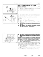
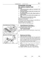
8. INSPECT CHARCOAL CANISTER
(a) Remove the canister dust cover.
M Disconnect the hoses from the charcoal canister.
Label hoses for correct installation.
(c) Plug pipe C with your finger, and blow compressed air
(3kg/cm
2
, 43 psi or 294 kPa) through pipe B (fuel tank
side).
• Check that air comes out of the bottom pipe A
without resistance.
• Check that no activated charcoal comes out.
If necessary, replace the charcoal canister.
NOTICE: Do not attempt to wash the charcoal.
(d) Reconnect the hoses to the charcoal canister.
(e) Reinstall the canister dust cover.
9. REPLACE GASKET IN FUEL TANK CAP
(a) Remove the old gasket (O–ring) from the tank cap. Do
not damage the cap.
(b) Install a new gasket by hand.
(c) Check the cap for damage or cracks.
(d) Install the cap and check the torque limiter.
–MAINTENANCE Maintenance Operations
MA–6
BRAKES
13. INSPECT BRAKE LINE PIPES AND HOSES
HINT: Check in a well lighted area. Check the entire circum-
ference and length of the brake hoses using a mirror
as required. Turn the front wheels fully right or left before
checking the front brake.
(a) Check all brake lines and hoses for:
• Damage
• Wear
• Deformation
• Cracks
• Corrosion
• Leaks
• Bends
• Twists
(b) Check all clamps for tightness and connections for
leakage.
(c) Check that the hoses and lines are clear of sharp
edges, moving parts and the exhaust system.
(d) Check that the lines installed in grommets pass through
the center of the grommets.
10. INSPECT FUEL LINES AND CONNECTIONS
Visually check the fuel lines for cracks, leakage, loose con-
nections, deformation or tank band looseness.
11. INSPECT EXHAUST PIPES AND MOUNTINGS
Visually check the pipes, hangers and connections for se-
vere corrosion, leaks or damage.
12. ADJUST VALVE CLEARANCE
3S–FE (See page EM–11)
2VZ–FE (See page EM–15)
Valve clearance (Cold):
3S–FE Intake 0.19 – 0.29 mm
(0.007 – 0.011 in.)
Exhaust 0.28 0.38 mm
(0.011 0.015 in.)
2VZ–FE Intake 0.13 – 0.23 mm
(0.005 – 0.009 in.)
Exhaust 0.27 – 0.37 mm
(0.011 – 0.015 in.)
–MAINTENANCE Maintenance Operations
MA–7
(d) Settle the parking brake shoes and drum. When per-
forming the road test in item 23, do the following:
• Drive the vehicle at approx. 50 km/h (30 mph) on a safe, lev-
el and dry road.
• With the parking brake release button pushed in, pull on the
lever with 9 kg (20 Ib, 88 N) of force.
• Drive the vehicle for approx. m (1 /4 mile) in this condition.
• Repeat this procedure 2 or 3 times.
• Check parking lever travel.
If necessary, adjust the parking brake.
15. INSPECT BRAKE PADS AND DISCS
Front (See page BR–26)
Rear (See page BR–42)
(a) Check the thickness of the disc brake pads and check
for irregular wear.
Minimum pad thickness: 1.0 mm (0.039 in.)
HINT: If a squealing or scraping noise comes from the brake
during driving, check the pad wear indicator to see if it is
contacting the disc rotor. If so, the disc pad should be re-
placed.
Minimum disc thickness:
Front 24.0 mm (0.945 in.)
Rear 9.0 mm (0.354 in.)
Maximum disc runout:
Front 0.07 mm (0.0028 in.)
Rear 0.15 mm (0.0059 in.)
CHASSIS
16. INSPECT STEERING LINKAGE
(a) Check the steering wheel freeplay.
Maximum steering wheel freeplay: 30 mm (1.18 in.)
With the vehicle stopped and pointed straight ahead, rock
the steering wheel gently back and forth with light fin-
ger pressure.
14. INSPECT BRAKE LININGS AND DRUMS
Drum brake (See page BR–31)
Disc brake (See page BR–47)
(a) Check the lining–to–drums contact condition and lin-
ing wear.
Minimum lining thickness: 1.0 mm (0.0039 in.)
(b) Check the brake drums for scoring or wear.
Maximum drum inside diameter:
Drum brake 230.6 mm (9.079 in.)
Disc brake 171.0 mm (6.732 in.)
(c) Clean the brake parts with a damp cloth.
HINT: Do not use compressed air to clean the brake parts.
–MAINTENANCE Maintenance Operations
MA–8
19. INSPECT BALL JOINTS AND DUST COVERS
(a) Inspect the ball joints for excessive looseness.
• Jack up the front of the vehicle and place wooden blocks
with a height of 180 – 200 m m (7.09–7.87 in.) under the
front tires.
• Lower the jack until there is about half a load on the front
coil springs. Place stands under the vehicle for safety.
• Check that the front wheels are in a straight forward posi-
tion, and block them with chocks.
• Using a lever, pry up the end of the lower arm, and check
the amount of play.
Maximum ball joint vertical play: 0mm (0 in.)
If there is play, replace the ball joint.
(b) Check the dust cover for damage.
(b) Check the steering linkage for looseness or damage.
Check that:
• Tie rod ends so not have excessive play.
• Dust seals and boots are not damage.
• Boot clamps are not loose.
17. INSPECT STEERING GEAR HOUSING OIL
Check the steering gear box for oil leakage.
18. INSPECT FRONT AND REAR DRIVE SHAFT BOOTS
Check the drive shaft boots for clamp looseness,
leakage or damage.
–MAINTENANCE Maintenance Operations
MA–9
B. (A/T)
Check automatic transaxle fluid
(a) Visually check the transaxle for fluid leakage.
If leakage is found, check for cause and repair.
(b) (Transmission (2WD))
Check the fluid level
If the level is low, add fluid.
Transmission fluid: See step 21 (D)
(c) (Transaxle (4WD))
Check the fluid level
If the level is low, add fluid.
Transaxle fluid: See step 21 (E)
(d) (Front Differential (2WD))
Remove the filler plug and feel inside the hole with
your finger. Check that the fluid comes to within 5 mm
(0.20 in.) of the bottom edge of the filler hole.
If the level is low, add fluid until it begins to run out the
filler hole.
Differential fluid: See step 21 (D)
20. CHECK TRANSAXLE, TRANSFER AND DIFFERENTIAL
OIL (FLUID)
A. (M/T)
Check manual transaxle oil (fluid)
(a)Visually check the transaxle for oil (fluid) leakage.
If leakage is found, check for cause and repair.
(b) Remove the filler plug and feel inside the hole with your
finger. Check that the oil (fluid) comes to within 5
mm (0.20 in.) of the bottom edge of the filler hole.
If the level is low, add oil (fluid) until it begins to run out
the fiIler hole.
Transaxle fluid:
2WD (3S–FE) See step 21 (A)
Transaxle oil:
2WD (2VZ–FE) See step 21 (B)
Transaxle oil (Incl. transfer):
4WD (3S–FE) See step 21 (C)
C. (4WD A/T) .
Check transfer oil
(a) Visually check the transaxle for oil leakage.
If leakage is found, check for cause and re-
pair.
(b) Check the oil level
If the level is low, add oil.
Transfer oil: See step 21 (F)
–MAINTENANCE Maintenance Operations
MA–10
D. (4WD)
Check Rear differential oil
(a) Visually check the differential for oil leakage.
If leakage is found, check for cause and repair.
(b) Remove the filler plug and feel inside the hole with your
finger. Check that the oil comes to within 5 mm
(0.20 in.) of the bottom edge of the filler hole.
If the level is low, add oil until it begins to run out the
filler hole.
Differential oil: See step 21 (G)
21. REPLACE TRANSAXLE, TRANSFER AND
DIFFERENTIAL OIL (FLUID)
A. (2WD M/T (3S–FE))
Replace transaxle fluid
(a) Remove the engine under cover.
(b) Remove the filler and drain plugs, and drain the fluid.
(c) Reinstall the drain plug securely.
(d) Add new fluid until it beings to run out of the filler hole.
Transaxle fluid: ATF DEXRONEII
Capacity: 2.6 liters (2.7 US qts, 2.3 Imp. qts)
(e) Reinstall the filler plug securely.
(f) Reinstall the engine under cover.
6. (2WD M/T (2vZ–FE))
Replace transaxle oil
(a) Remove the engine under cover.
(b) Remove the filler and drain plugs, and drain the oil.
(c) Reinstall the drain plug securely.
(d) Add new oil until it begins to run out of the filler hole.
Transaxle oil:
Oil grade API GL–4 or GL–5
Viscosity SAE 75W–9O or 80W–90
Capacity: 4.2 liters (4.4 US qts, 3.7 Imp. qts)
(e) Reinstall the filler plug securely.
(f) Reinstall the engine under cover.
–MAINTENANCE Maintenance operations
MA–11
C. (4WD M/T (3S–FE))
Replace transaxle (incl. transfer) oil
(a) Remove the engine under cover.
(b) Remove the filler and drain plugs, and drain the oil.
(c) Reinstall the drain plug securely.
(d) Add new oil until it begins to run out of the filler hole.
Transaxle oil: Transaxle oil E50 (08885–80206) or equiv-
alent
Recommended transaxle oil:
Oil grade API GL–5
Viscosity SAE 75w–90 or 80W–90
Above –18
°C (0°F) SAE 90
Below –18°C (0°F) SAE 80W
Capacity: 5.0 liters (5.3 US qts, 4.4 Imp. qts)
(e) Reinstall the filler plug securely.
(f) Reinstall the engine under cover.
(d) with the engine OFF, add new fluid through the
dipstick tube.
Transmission fluid: ATF DEXRONEII
Drain and refill capacity: 2.5 liters
(2.6 us qts, 2.2 Imp. qts)
(e) Start the engine and shift the selector into all posi-
tions from ”f’” through ”L”, and then shift into ”P”.
(f) With the engine idling, check the fluid level. Add
fluid up to the ”COOL” level on the dipstick.
NOTICE: Do not overfill. The transmission and differ-
ential are separate units.
(g) Recheck the fluid level with the normal tempera-
ture (70 – 80
°C (158 – 176°F)) and add as neces-
sary.
(h) Reinstall the engine under cover.
D. (2WD A/T)
Replace transaxle fluid
(Transmission)
(a) Remove the engine under cover.
(b) Using a 10 mm hexagon wrench, remove the drain
plug and drain the fluid.
(e) Reinstall the drain plug securely.
–MAINTENANCE Maintenance Operations
MA–12
(Front Differential)
(a) Remove the engine under cover.
(b) Using a 10 mm hexagon wrench, remove the
drain plug and drain the fluid.
(c) Reinstall the drain plug securely.
(d) Add new fluid until it beings to run out of the filler
hole.
Transaxle fluid: ATF DEXRONEII
Capacity: 3S–FE 1.6 liters
(1.7 US qts, 1.4 Imp. qts)
2VZ–FE 1.0 liters
(1.1 US qts, 0.9 Imp. qts)
(e) Reinstall the filler plug securely.
(f) Reinstall the engine under cover.
(d) With the engine OFF, add new fluid through the dip-
stick tube.
Transaxle fluid: ATF Type T (O8886–08405) or equiva
lent
Drain and refill capacity:
3.5 liters (3.7 US dts, 3.0 Imp. qts)
(e) Start the engine and shift the selector into all
positions from ”P” through ”L”, and then shift
into ”P”.
(f) With the engine idling, check the fluid level. Add
fluid up to the ”COOL” level on the dipstick.
NOTICE: Do not overfill.
(g) Recheck the fluid level with the normal tempera-
ture (70 80°C (158 176°F)) and add as neces-
sary.
(h) Reinstall the engine under cover.
E. (4WD A/T (3S–FE))
Replace transaxle fluid
(a) Remove the engine under cover.
(b) Using a 1 0 mm hexagon wrench, remove the drain
plugs and drain the fluid.
(c) Reinstall the drain plug securely.
–MAINTENANCE Maintenance Operations
MA–13
G. (4WD)
Replace rear differential oil
(a) Remove the filler and drain plugs, and drain the oil.
(b) Reinstall the drain plug securely.
(c) Add new oil until it beings to run out of the filler hole.
Rear differential oil:
Oil grade API GL–5 hypoid gear oil
Viscosity Above –18°C (0°F) SAE 90
Below –18°C (0°F) SAE 80W–90
Capacity: 1.1 liters (1.2 U S qts, 1.0 Imp. qts)
(d) Reinstall the filler plug securely.
22. TIGHTEN BOLTS AND NUTS ON CHASSIS AND BODY
Tighten the following parts:
• Front seats mount bolts
Torque: 375 kg–cm (27 ft–Ib, 37 N–m)
(d) Add new oil through the dipstick tube.
Transaxle oil: Transaxle oil E50 (08885–80206) or
equivalent
Recommended transaxle oil:
Oil grade API GL–5
Viscosity SAE 75W–90 or 80w–90
Above –18°C (0°F) SAE 90
Below –18°C (0°F) SAE 80W
Capacity: 0.7 liters (0.74 US qts, 0.62 Imp. qts)
F. (4WD A/T)
Replace transfer oil
(a) Remove the engine under cover.
(b) Using a 10 mm hexagon wrench, remove the drain plug
and drain the oil.
(c) Reinstall the drain plug securely.
(e) Check the oil level and add as neces-
sary.
M Reinstall the engine under cover.
–MAINTENANCE Maintenance Operations
MA–14
23. FINAL INSPECTION
(a) Check the operation of the body parts:
• Hood
Auxiliary catch operation properly
Hood locks securely when closed
• Front and rear doors
Door locks operate properly
Doors close properly
• Luggage compartment door and back door
Door sock operates properly
• Seats
Seat adjusts easily and locks securely in any position
Front seat back locks securely in any position
Folding–down rear seat backs lock securely
(b) Road test
• Check the engine and chassis for abnormal noises.
• Check that the vehicle does not wander or pull to one side.
• Check that the brakes work properly and do not drag.
• Perform bedding down of the parking brake shoes and drum.
(See page MA–8)
(c) Be sure to deliver a clean car especially check:
• Steering wheel
• Shift lever knob
• All switch knobs
• Door handles
• Seats
• Strut/stabilizer bar bracket–to–body mount bolts
(LH and RH)
Torque: 620 kg–cm (45 ft–lb, 61 N–m)
• Engine mounting center member–to–body mount bolts
Torque: 400 kg–cm 129 ft–lb, 39 N–m)
• Front suspension lower cross member–to–body mount
bolts
Torque: 2,110 kg–cm (153 ft–Ib, 206 N–m)
• Rear suspension lower crossmember–to–body mount
bolts
Torque: 2WD 710 kg–cm (51 ft–lb, 70 N–m)
4WD 1,620 kg–cm (117 ft–Ib, 159 N–m)
–MAINTENANCE Maintenance Operations
MA–15