Toyota land cruiser 1998 2007 SFI hệ thống điều khiển chân ga điện tử trên xe land cruiser đời 1998 2007
Bạn đang xem bản rút gọn của tài liệu. Xem và tải ngay bản đầy đủ của tài liệu tại đây (1.59 MB, 60 trang )
SF1UM-03
B16380
B16465
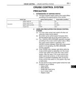
Accelerator Pedal
Assembly
N·m (kgf·cm, ft·lbf) : Specified torque
Accelerator Pedal
Position Sensor
Accelerator Pedal Position
Sensor Connector
5.0 (51, 44 in.·lbf)
SF-58
-SFI ACCELERATOR PEDAL POSITION SENSOR
1757Author: Date:
2004 LAND CRUISER (RM1071U)
ACCELERATOR PEDAL POSITION SENSOR
COMPONENTS
SF1UN-03
-SFI ACCELERATOR PEDAL POSITION SENSOR
SF-59
1758Author: Date:
2004 LAND CRUISER (RM1071U)
INSPECTION
INSPECT ACCELERATOR PEDAL POSITION SENSOR (See page DI-318 )
If necessary, replace the accelerator pedal assembly.
NOTICE:
z Be careful not to give a shock to the accelerator pedal assembly.
z Be careful not to disassemble the accelerator pedal assembly.
B16460
Circuit
Opening
Relay
SF136-06
S04947
Continuity
2
1
No Continuity
Ohmmeter
Ohmmeter
3
5
S04946
Continuity
Ohmmeter
Battery
2
1
3
5
-SFI CIRCUIT OPENING RELAY
SF-39
1738Author: Date:
2004 LAND CRUISER (RM1071U)
CIRCUIT OPENING RELAY
INSPECTION
1. REMOVE RELAY BOX COVER
2. REMOVE CIRCUIT OPENING RELAY
(Marking: C/OPN)
3. INSPECT CIRCUIT OPENING RELAY CONTINUITY
(a) Using an ohmmeter, check that there is a continuity be-
tween terminal 1 and 2.
If there is no continuity, replace the relay.
(b) Check that there is no continuity between terminal 3 and
5.
If there is a continuity, replace the relay.
4. INSPECT CIRCUIT OPENING RELAY OPERATION
(a) Apply the battery positive voltage across terminal 1 and
2.
(b) Using an ohmmeter, check that there is a continuity be-
tween terminal 3 and 5.
If there is no continuity, replace the relay.
5. REINSTALL CIRCUIT OPENING RELAY
6. REINSTALL RELAY BOX COVER
SF0Q0-12
B16466
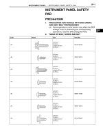
ECM Connector
ECM and Bracket Assembly
Glove Compartment Door
Lower No.2
Finish Panel
ECM
Bracket
ECM Bracket
ECM
Glove Compartment Door Damper
SF-60
-SFI ENGINE CONTROL MODULE (ECM)
1759Author: Date:
2004 LAND CRUISER (RM1071U)
ENGINE CONTROL MODULE (ECM)
COMPONENTS
SF0Q1-02
-SFI ENGINE CONTROL MODULE (ECM)
SF-61
1760Author: Date:
2004 LAND CRUISER (RM1071U)
INSPECTION
1. REMOVE ECM
2. INSPECT ECM (See page DI-46 )
3. REINSTALL ECM
SF0PN-11
B16453
V-Bank Cover
PS Air Hose
Air Inlet Hose for EVAP
PCV Hose
Intake Air Connector
z Gasket
ECT Sensor
Connector
ECT Sensor
N·m (kgf·cm, ft·lbf) : Specified torque
18 (185, 13)
z Gasket
z Non-reusable part
Vacuum Sensing Hose
Fuel Return Hose
Water Bypass Hose
Throttle Control Connector
Throttle Body
Water Bypass Hose
PCV Hose
-SFI ENGINE COOLANT TEMPERATURE (ECT) SENSOR
SF-49
1748Author: Date:
2004 LAND CRUISER (RM1071U)
ENGINE COOLANT TEMPERATURE (ECT) SENSOR
COMPONENTS
SF0PO-17
B02308
S01196
S01699 Z17274
Ohmmeter
Resistance kΩ
Temperature °C (°F)
Acceptable
30
20
10
5
3
2
1
0.5
0.3
0.2
0.1
40-20 0 20 60 80 100
(212)(176)(140)(104)(68)(32)(-4)
SF-50
-SFI ENGINE COOLANT TEMPERATURE (ECT) SENSOR
1749Author: Date:
2004 LAND CRUISER (RM1071U)
INSPECTION
1. DRAIN ENGINE COOLANT
2. REMOVE V-BANK COVER
3. REMOVE INTAKE AIR CONNECTOR
4. DISCONNECT THROTTLE BODY FROM INTAKE MAN-
IFOLDS (See page SF-36 )
5. REMOVE ECT SENSOR
(a) Disconnect the ECT sensor connector.
(b) Remove the ECT sensor and the gasket.
6. INSPECT ECT SENSOR
Using an ohmmeter, measure the resistance between the ter-
minals.
Resistance: Refer to the graph
If the resistance is not as specified, replace the ECT sensor.
7. REINSTALL ECT SENSOR
(a) Install a new gasket and the ECT sensor.
Torque: 20.4 N·m (208 kgf·cm, 15 ft·lbf)
(b) Connect the ECT sensor connector.
8. REINSTALL THROTTLE BODY TO INTAKE MAN-
IFOLDS
Install a new gasket and the throttle body with the 2 bolts and
2 nuts.
Torque: 18 N·m (185 kgf·cm, 13 ft·lbf)
9. REINSTALL INTAKE AIR CONNECTOR
10. REFILL WITH ENGINE COOLANT (See page CO-2 )
11. REINSTALL V-BANK COVER
B16461
EFI Main Relay
SF06G-18
B04910
Continuity
Ohmmeter
Ohmmeter
No
Continuity
1
2
34
B04911
Battery
Ohmmeter
Continuity
1
2
34
SF-38
-SFI EFI MAIN RELAY
1737Author: Date:
2004 LAND CRUISER (RM1071U)
EFI MAIN RELAY
INSPECTION
1. REMOVE RELAY BOX COVER
2. REMOVE EFI MAIN RELAY (Marking: EFI)
3. INSPECT EFI MAIN RELAY
(a) Inspect the relay continuity.
(1) Using an ohmmeter, check that there is a continuity
between terminal 1 and 3.
If there is no continuity, replace the relay.
(2) Check that there is no continuity between terminals
2 and 4.
If there is a continuity, replace the relay.
(b) Inspect the relay operation.
(1) Apply battery positive voltage across terminals 1
and 3.
(2) Using an ohmmeter, check that there is a continuity
between terminal 2 and 4.
If there is no continuity, replace the relay.
4. REINSTALL EFI MAIN RELAY
5. REINSTALL RELAY BOX COVER
SF0Q2-14
A07061
TOYOTA
Hand-Held
Tester
DLC3
B04432
Sound Scope
SF-62
-SFI FUEL CUT RPM
1761A uthor: Date:
2004 LAND CRUISER (RM1071U)
FUEL CUT RPM
INSPECTION
1. WARM UP ENGINE
Allow the engine to warm up to normal operating temperature.
2. CONNECT TOYOTA HAND-HELD TESTER OR OBDII
SCAN TOOL
(a) Connect the TOYOTA hand-held tester or OBDII scan
tool to the DLC3.
(b) Please refer to the TOYOTA hand-held tester or OBDII
scan tool operator’s manual for further details.
3. INSPECT FUEL CUTOFF RPM OPERATION
(a) Increase the engine speed to at least 2,500 rpm.
(b) Check the injector for operating noise.
(c) Check that when the throttle lever is released, injector op-
eration noise stops momentarily and then resumes.
HINT:
z The vehicle should be at at rest during the inspection.
z Inspection with the A/C OFF.
Fuel return speed: 1,000 rpm
4. DISCONNECT TOYOTA HAND- HELD TESTER OR
OBDII SCAN TOOL
SF0XZ-11
B04926
V-Bank Cover
Vacuum Sensing Hose
Fuel Return Hose
Fuel Pressure Regulator
N·m (kgf·cm, ft·lbf)
z Non-reusable part
: Specified torque
7.5 (80, 66 in.·lbf)
z O-Ring
Fuel Return Hose
Delivery Pipe
SF-16
-SFI FUEL PRESSURE REGULATOR
1715Author: Date:
2004 LAND CRUISER (RM1071U)
FUEL PRESSURE REGULATOR
COMPONENTS
B04906
Install
Turn
SF0Y1-11
B04905
SF-18
-SFI FUEL PRESSURE REGULATOR
1717Author: Date:
2004 LAND CRUISER (RM1071U)
INSTALLATION
1. INSTALL FUEL PRESSURE REGULATOR
(a) Apply a light coat of gasoline to a new O-ring, and install
it to the fuel pressure regulator.
(b) While turning the fuel pressure regulator left and right,
install it to the delivery pipe.
(c) Install the fuel pressure regulator with the 2 bolts.
Torque: 7.5 N·m (80 kgf·cm, 66 in.·lbf)
(d) Connect the vacuum sensing hose to the fuel pressure
regulator.
(e) Connect the fuel return hose to the pressure regulator.
2. CHECK FOR FUEL LEAKS (See page SF-1 )
3. INSTALL V-BANK COVER
B04905
SF0Y0-08
B04993
-SFI FUEL PRESSURE REGULATOR
SF-17
1716Author: Date:
2004 LAND CRUISER (RM1071U)
REMOVAL
1. REMOVE V-BANK COVER
2. REMOVE FUEL PRESSURE REGULATOR
(a) Disconnect the vacuum sensing hose from the fuel pres-
sure regulator.
(b) Disconnect the fuel return hose from the fuel pressure
regulator.
CAUTION:
Put a shop rag under the fuel pressure regulator.
(c) Remove the 2 bolts, and pull out the pressure regulator.
(d) Remove the O-ring from the fuel pressure regulator.
I25156
Fuel Pump
Relay
SF137-06
B07643
Continuity
2
1
Ohmmeter
Ohmmeter
3
No Continuity
5
B07644
2
1
Ohmmeter
3
5
Battery
Continuity
SF-40
-SFI FUEL PUMP RELAY
1739A uthor: Date:
2004 LAND CRUISER (RM1071U)
FUEL PUMP RELAY
INSPECTION
1. REMOVE RELAY BOX COVER
2. REMOVE FUEL PUMP RELAY (Marking: F/PUMP)
3. INSPECT FUEL PUMP RELAY CONTINUITY
(a) Using an ohmmeter, check that there is a continuity be-
tween terminal 1 and 2.
If there is no continuity, replace the relay.
(b) Check that there is no continuity between terminals 3 and
5.
If there is a continuity, replace the relay.
4. INSPECT FUEL PUMP RELAY OPERATION
(a) Apply the battery positive voltage across terminal 1 and
2.
(b) Using an ohmmeter, check that there is a continuity be-
tween terminal 3 and 5.
If there is no continuity, replace the relay.
5. REINSTALL FUEL PUMP RELAY
6. REINSTALL RELAY BOX COVER
SF138-04
B16448
Fuel Pump Resistor
N⋅m (kgf⋅cm, ft⋅lbf) : Specified torque
12 (122, 8.8)
-SFI FUEL PUMP RESISTOR
SF-41
1740A uthor: Date:
2004 LAND CRUISER (RM1071U)
FUEL PUMP RESISTOR
COMPONENTS
SF139-04
B16449
Ohmmeter
SF-42
-SFI FUEL PUMP RESISTOR
1741A uthor: Date:
2004 LAND CRUISER (RM1071U)
INSPECTION
1. REMOVE FUEL PUMP RESISTOR
2. INSPECT FUEL PUMP RESISTOR
Using an ohmmeter, measure the resistance between the ter-
minals.
Resistance: 0.70 - 0.76 Ω at 20°C (68°F)
If the resistance is not as specified, replace the resistor.
3. REINSTALL FUEL PUMP RESISTOR
Torque: 12 N·m (122 kgf·cm, 8.8 ft·lbf)
SF0OZ-15
B16457
Location of Fuel Tank Cushion
Fuel Return Hose
Fuel Inlet Pipe
Fuel Tank Cap
Cutoff
Valve
Ring
1.5 (15, 13 in.·lbf)
Fuel Inlet Pipe Protector
Fuel Inlet Pipe Shield
Gasket
3.5 (35, 31 in.·lbf)
Gasket
Fuel Tank Wire
Fuel Inlet Hose
Fuel Tank
Protector
Fuel Tank Band
N·m (kgf·cm, ft·lbf) : Specified torque
Non-reusable part
40 (408, 30)
40 (408, 30)
Ring
Fuel Tank Filler Pipe
x 8
3.5 (35, 31 in.·lbf)
Fuel Tank Vent
Tube Set Plate
Fuel pump and
Sender Gauge
Assembly
Fuel Tank
Parking Brake Cable
Cutoff
Valve
Cover
EVAP Tube
Fuel Main Tube
Fuel Return Tube
Bracket
Gasket
20 (204, 15)
-SFI FUEL TANK AND LINE
SF-29
1728A uthor: Date:
2004 LAND CRUISER (RM1071U)
FUEL TANK AND LINE
COMPONENTS
CAUTION:
z Always use new gaskets when replacing the fuel tank or component parts.
z Apply the proper torque to all tightening parts.
SF0P0-12
BO0919
Crack Leakage
Deformation
FU0041
Pipe
Clip
2 - 7 mm (0.08 - 0.28 in.)
0 - 3 mm (0 - 0.12 in.)
Hose
B05015
Clamp
0 - 3 mm
(0 - 0.12 in.)
Area
Fuel Inlet Hose
SF-30
-SFI FUEL TANK AND LINE
1729A uthor: Date:
2004 LAND CRUISER (RM1071U)
INSPECTION
INSPECT FUEL TANK AND LINE
(a) Check the fuel lines from cracks or leakage, and all con-
nections for deformation.
(b) Check the fuel tank vapor vent system hoses and all con-
nections for looseness, sharp bends or damage.
(c) Check the fuel tank for deformation, cracks, fuel leakage
or tank band looseness.
(d) Check the filler neck for damage or fuel leakage.
(e) Hose and pipe connections are as shown in the illustra-
tion.
If a problem is found, repair or replace the parts as necessary.
SF0XW-05
B06489
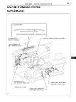
No.1 Rear Seat
Rear Seat Lock Cover
Front Floor Carpet
Leg Cover
Rear Floor Carpet
Rear Floor Service
Hole Cover
Rear Door Scuff Plate
Step Plate
N·m (kgf·cm, ft·lbf) : Specified torque
41 (420, 30)
SF-10
-SFI FUEL PUMP
1709A uthor: Date:
2004 LAND CRUISER (RM1071U)
COMPONENTS
B16438
Fuel Main Tube
Tube Joint Clip
Fuel Pump & Sender Gauge
Connector
Fuel Tank Vent Tube Set Plate
Fuel Pump and Sender
Gauge Assembly
z Gasket
Tube Joint Clip
N·m (kgf·cm, ft·lbf) : Specified torque
z Non-reusable part
3.5 (35, 31 in.·lbf)
Vapor Pressure Sensor & Connector
Fuel Return Tube
x 8
Tube Joint Clip
Tube Joint Clip
-SFI FUEL PUMP
SF-1 1
1710A uthor: Date:
2004 LAND CRUISER (RM1071U)
B16439
Fuel Pump Filter
z Clip
Rubber Cushion
Fuel Suction Plate
with Sender Gauge
Lead Wire
Fuel Hose
Fuel Pump
z Non-reusable part
SF-12
-SFI FUEL PUMP
1711A uthor: Date:
2004 LAND CRUISER (RM1071U)
B04997
Push
SF0XY-04
B16442
B16443
Insert
Insert Insert
B16444
Clip
Clip
-SFI FUEL PUMP
SF-15
1714A uthor: Date:
2004 LAND CRUISER (RM1071U)
INSTALLATION
1. INSTALL FUEL PUMP FILTER TO FUEL PUMP
Install the pump filter with a new clip.
2. INSTALL FUEL PUMP TO FUEL PUMP BRACKET
(a) Install the rubber cushion to the fuel pump.
(b) Connect the fuel hose to the outlet port of the fuel pump.
(c) Install the fuel pump by pushing the lower side of the fuel
pump.
3. INSTALL LEAD WIRE TO FUEL PUMP
4. INSTALL FUEL PUMP AND SENDER GAUGE AS-
SEMBLY TO FUEL TANK
(a) Install a new gasket to the fuel suction plate.
(b) Insert the fuel pump and the sender gauge assembly into
the fuel tank.
(c) Install the fuel tank vent tube set plate with the 8 bolts.
Torque: 3.5 N·m (35 kgf·cm, 31 in.·lbf)
5. CONNECT FUEL MAIN TUBE AND RETURN TUBE
(FUEL TUBE CONNECTORS) TO FUEL SUCTION
PLATE
(a) Before installing the tube connectors, check foreign mat-
ters on the connection between the nylon tube and the
suction plate.
(b) Attach the fuel tube connectors to the ports of the fuel suc-
tion plate and insert the clips until you hear a click.
(c) After the connection, pull out the clips to check to see that
they are installed securely.
6. CONNECT FUEL PUMP & SENDER GAUGE CONNEC-
TOR
7. CHECK FOR FUEL LEAKS (See page SF-1 )
8. INSTALL REAR FLOOR SERVICE HOLE COVER
(a) Install the rear service hole cover with the 2 screws.
(b) Cover the rear and front floor carpets.
9. INSTALL REAR DOOR SCUFF PLATES, STEP
PLATES AND REAR SEAT LOCK COVERS
10. INSTALL NO.1 REAR SEATS
A07061
TOYOTA
Hand-Held
Tester
DLC3
SF10V-02
B04440
Up
Pulsation
Damper
Screw
B04441
SST
(Gauge)
SST
(Adaptor)
SST
(Union)
Front Fuel Pipe
Gasket
-SFI FUEL PUMP
SF-7
1706A uthor: Date:
2004 LAND CRUISER (RM1071U)
FUEL PUMP
ON-VEHICLE INSPECTION
1. CHECK FUEL PUMP OPERATION
(a) Connect a TOYOTA hand-held tester or OBD II scan tool
to the DLC3.
(b) Turn the ignition switch ON, and press the TOYOTA
hand-held tester or OBD II scan tool main switch ON.
NOTICE:
Do not start the engine.
(c) Select the ACTIVE TEST mode on the TOYOTA hand-
held tester or OBD II scan tool.
(d) Please refer to the TOYOTA hand-held tester or OBD II
scan tool operator’s manual for further details.
(e) If you have no TOYOTA hand-held tester or OBD II scan
tool, connect the positive (+) and negative (-) leads from
the battery to the fuel pump connector. (See step 3)
(f) Disconnect the fuel return hose from the clamp on the V-
bank cover.
(g) Remove the 2 bolts, nuts and V-bank cover.
(h) Check that the pulsation damper screw pop up when the
fuel pump operates.
If operation is not as specified, check following parts:
z Fusible link
z Fuses
z EFI main relay
z Fuel pump
z ECM
z Wiring connections
(i) Turn the ignition switch OFF.
(j) Disconnect the TOYOTA hand-held tester or OBD II scan
tool from the DLC3.
2. CHECK FUEL PRESSURE
(a) Check the battery positive voltage is above 12 V.
(b) Disconnect the negative (-) terminal cable from the bat-
tery.
(c) Remove the front fuel pipe from the LH delivery pipe (See
page SF-22 ).
(d) Install the front fuel pipe and SST (pressure gauge) to the
delivery pipe with the 3 lower gaskets and SST (adaptor).
SST 09268-45014 (09268-41190, 90405-06167)
Torque: 39 N·m (400 kgf·cm, 29 ft·lbf)
(e) Wipe off any splattered gasoline.
(f) Reconnect the negative (-) terminal cable to the battery.
(g) Connect a TOYOTA hand-held tester or OBD II scan tool
to the DLC3 (See (a) to (e) in step 1 on the check fuel
pump operation).
(h) Measure the fuel pressure.
B16435
Ohmmeter
5
4
SF-8
-SFI FUEL PUMP
1707A uthor: Date:
2004 LAND CRUISER (RM1071U)
Fuel pressure:
265 - 304 kPa (2.7 - 3.1 kgf/cm
2
, 38 - 44 psi)
If pressure is higher than the specification, replace the fuel
pressure regulator.
If pressure is lower than the specification, check these parts:
z Fuel hoses and connections
z Fuel pump
z Fuel filter
z Fuel pressure regulator
(i) Disconnect the TOYOTA hand- held tester from the
DLC3.
(j) Start the engine.
(k) Measure the fuel pressure at idle.
Fuel pressure:
265 - 304 kPa (2.7 - 3.1 kgf/cm
2
, 38 - 44 psi)
(l) Stop the engine.
(m) Check that the fuel pressure remains in the specification
below for 5 minutes after the engine stop.
Fuel pressure:
147 kPa (1.5 kgf/cm
2
, 21 psi) or more
If the pressure is not as specified, check the fuel pump, pres-
sure regulator and/or the injectors.
(n) After checking the fuel pressure, disconnect the negative
(-) terminal cable from the battery and carefully remove
the SST to prevent gasoline from splashing.
SST 09268-45014
(o) Reinstall the front fuel pipe to the LH delivery pipe (See
page SF-27 ).
(p) Reconnect the negative (-) terminal cable to the battery.
(q) Check for fuel leaks (See page SF-1 ).
(r) Reinstall the V-bank cover with the 2 bolts and nuts.
(s) Reconnect the fuel return hose to the clamp on the V-
bank cover.
3. INSPECT FUEL PUMP
(a) Remove the No.1 rear seats.
(b) Remove the 2 rear door scuff plates, the step plates and
the rear seat lock covers.
(c) Pull off the front and rear floor carpets.
(d) Remove the 2 screws and the rear floor service hole cov-
er.
(e) Disconnect the fuel pump & sender gauge connector.
(f) Using an ohmmeter, measure the resistance between ter-
minal 4 and 5.
B16436
Battery
4
5
-SFI FUEL PUMP
SF-9
1708A uthor: Date:
2004 LAND CRUISER (RM1071U)
Resistance: 0.2 - 3.0 Ω at 20°C (68°F)
If the resistance is not as specified, replace the fuel pump and/
or the lead wire.
(g) Inspect the fuel pump operation.
Connect the battery positive (+) lead to terminal 4 of the
connector, and the battery negative (-) lead to terminal 5.
Check that the fuel pump operates.
NOTICE:
z These tests must be done quickly (within 10 seconds)
to prevent the coil burning out.
z Keep the fuel pump as far away from the battery as
possible.
z Always change the connection on the battery side.
If operation is not as specified, replace the fuel pump and/or
lead wire.
(h) Reconnect the fuel pump & sender gauge connector.
(i) Reinstall the rear floor service hole cover with the 2
screws.
(j) Reinstall the front and rear floor carpets.
(k) Remove the 2 rear door scuff plates, the step plates and
the rear sear lock covers.
(l) Reinstall the No.1 rear seats.
SF0XX-04
B16440
Pull
Enlarge
Tube Joint
Clip
B16441
Plug
Turn
Turn
-SFI FUEL PUMP
SF-13
1712A uthor: Date:
2004 LAND CRUISER (RM1071U)
REMOVAL
CAUTION:
Do not smoke or work near an open frame when working
the fuel pump.
1. REMOVE NO.1 REAR SEATS
2. REMOVE REAR DOOR SCUFF PLATES, STEP
PLATES AND REAR SEAT LOCK COVERS
3. REMOVE REAR FLOOR SERVICE HOLE COVER
(a) Take off the front and rear floor carpets.
(b) Remove the 2 screws and rear floor service hole cover.
4. DISCONNECT FUEL PUMP & SENDER GAUGE CON-
NECTOR
5. DISCONNECT FUEL MAIN TUBE AND RETURN TUBE
(FUEL TUBE CONNECTORS) FROM FUEL SUCTION
PLATE
CAUTION:
z Perform disconnecting operation of the fuel tube con-
nector (quick type) after reading the precautions.
(See page SF-1 )
z Prevent the retained pressure in the fuel line from
splashing inside the vehicle compartment.
z Be careful not to damage the contact surface or let the
foreign matters on there when sealing the tube and
the suction plates with the quick connectors through
O-ring.
z Be sure to perform the disconnection by hand. Do not
use tools.
z Do not bend or turn the nylon tube by force.
(a) Before the operation, remove foreign matters or dirt stick-
ing to the tube joint clips.
(b) Enlarge the tip of the clips with fingers and pull them out
for disconnection.
(c) Pull out the fuel main tube and the return tube.
If the nylon tube and the suction plate stick together, ease the
connection by turning the nylon tube with fingers and pull it out
for disconnection.
NOTICE:
Plug the port of the fuel suction plate with a clean rubber
cap.
(d) After the disconnection, protect the connector with a plas-
tic bag.