Human Musculoskeletal Biomechanics Part 5 pptx
Bạn đang xem bản rút gọn của tài liệu. Xem và tải ngay bản đầy đủ của tài liệu tại đây (3.05 MB, 20 trang )
Biomechanical Characteristics of the Bone
71
We can also cite as compressive strength on the temporomandibular joint (TMJ) the role of
sternocleidomastoid muscles when accommodated and shortened to a particular situation.
They exert this kind of strength on the mandibular condyles, thus changing the whole
mastication and mandibular morphology and may cause damage to joints and headache.
This happens due to the insertion of the sternocleidomastoid be in the mastoid process of
the temporal bone, exactly in the bone where the jaw is articulated, and because these are
anti-gravity muscles in relation to its origins and insertions. (Halpbern et al., 1987; Matheson
et al., 1987).
Tensive Strengths — A tensive strength is usually applied on the bone surface and it pulls or
elongates the bone, tending it to extend and narrow the bone (FIGURE 1.9 A and B). The
maximum stress, as in compression is perpendicular to the applied load. The source of tensive
strength is usually the muscle. When the muscle applies a tensive strength to the system by the
tendon, the collagen in the bone tissue is aligned with the tensive strength of the tendon. (See
FIGURE 1.13 — an example of alignment of collagen in the tibial tuberosity). This figure also
illustrates the influence of tensive strengths in development of apophyses, showing how the
tibial tuberosity is formed by tensive strengths. The failure of the bone usually occurs at the
site of muscle insertion. Tensive strengths can also create ligament avulsions that occur more
frequently in children. In addition, the ligament avulsions are common in lateral ankle because
of ankle sprain. (Choi & Goldstein, 1992; Cook et al., 1987).
Besides the bone tissue, here are other examples of biomechanical properties of connective
tissue, represented by tendons and ligaments. Biomechanical properties of tendons and
ligaments are often characterized as a relation load versus deformation in response to a
tensive load (FIGURE 1.10 ). In these experiments, a sample (e.g., ligament, tendon, and
ligament-bone) is obtained from a corpse, and is assembled on a device that elongates the
tissue to a prescribed speed (distension speed) until the tissue is broken, and measures the
displacement (elongation) and strength. The clinical observations on the disruption of the
connective tissue suggest that tissular breakdown is more common than avulsion of the
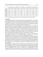
bone. (FIGURE 1.10) shows the variation in peak strength and elongation in different
samples. For example, a sample medial patellar tendon-bone was elongated by 10 mm and a
tensive strength exerted peak (
rupture
) of about 3 kN before starting to fail, while a sample
of anterior cruciate ligament-bone was elongated by 15 mm and exerted a tensive strength
of peak (
rupture
) of approximately 1.5 kN before failing. The data shown in Figure 1.10 were
taken from a study comparing the mechanical properties from several collagen tissues for
use in the reconstruction of the articular cartilage of the knee joint. The gracilis tendon is the
tissue between the muscle and the tibial insertion. (Lakes et al., 1990).
A sample of the fascia lata had 70 to 10 cm wide and was taken from the middle of the thigh
near the lateral femoral condyle. The data indicate that the patellar tendon-bone sample was
stronger than the sample anterior cruciate ligament-bone, but both were stronger than the
samples of the gracilis tendon and fascia lata (FIGURE 1.10) When the load and deformation
are normalized so that the load is expressed per unit of cross-sectional area and deformation
is described as a percentage of the initial length, the biomechanical properties of tissues can
be compared to overload versus distension relations. FIGURE 1.11 represents an overload
relation versus distension idealized for collagen tissues, like tendons and ligaments. The
overload relation versus distension comprises three regions: tip, linear and rupture. The
region of the tip corresponds to the initial part of the relationship, in which the collagen
fibers are elongated and rectified from the standard of rest in a zigzag. The linear region
represents the ability of elastic tissue; the inclination of the relation in this region is called
Human Musculoskeletal Biomechanics
72
the elastic modulus and is more pronounced in tissues that are more rigid. Outside of linear
region, the inclination decreases, since some fibers are broken in the region of rupture.
Fig. 1.10. The load versus deformation relationships for the sample of connective tissue
elongated up to rupture. Bankoff (2007, p. 127).
When the connective tissue experiences a distension of this magnitude, the tissue undergoes
plastic changes and there is a change in its resting length. From of overload relation versus
distension, the tissue can be characterized by measures of final overload ( final) of final
distension ( final) of the elastic modulus and the energy absorbed (area under curve;
overload versus distension). These properties tend to decline in the face of conditions such
as reduced use (e.g., immobilization, bed rest), aging and steroid use, but increases with
long-term exercise. Moreover, the properties of tendon may vary with the muscle function.
(Lakes et al., 1990; Matheson et al., 1987).
Tendo
n
fascia lata muscle
Tendo
n
g
racile muscle
Power (KN)
Medial
p
atellar tendo
n
Anterior Cruciate Li
g
ament
Len
g
th
(
mm
)
Biomechanical Characteristics of the Bone
73
Fig. 1.11. Relation of overload versus distension idealized for collagen tissue. The tissue may
experience only a small change in length before being damaged. Bankoff (2007, p. 128).
The avulsion fractures occur when the tensive strength of the bone is not sufficient to
prevent fracture. This is typical in some injuries that occur in movements of high-speed
pitch, as in the arm of throw, sore of basketball of junior players. The avulsion fracture in
this case is usually in the medial epicondyle due to the tension generated in the wrist
flexors. (Lakes et al., 1990).
Two other fractures produced by common tension, are in the fifth metatarsal due to tensive
strengths, generated by fibular muscle group, and in the calcaneus where the triceps surae
muscle generates the strengths. The tensive strength on the calcaneus can also be produced
in the support phase of walking to the extent that the arc is depressed and the plantar fascia
that covers the plantar surface of the foot is tensioned, exerting a tensive strength on the
calcaneus. Some sites of avulsion fractures in the pelvic region, shown in Figure 1.14,
include the upper and lower spines, the lesser trochanter, the ischial tuberosity and the
pubic bone. (Lakes et al., 1990; Mundy et al., 1995).
Tensive strengths are mostly responsible for distensions and sprains. For example, a typical
ankle sprain in inversion occurs when the foot, rolls to the side, elongating the ligaments.
Tensive strengths are also identified with canelite when the anterior tibial pulls its insertion
site and the interosseous membrane. (Bechtol, 1954). Another body part exposed to high
tensive strength is the tibial tuberosity that transmits very high tensive strength when the
quadriceps femoris muscle group is active. This tensive strength, under sufficient
magnitude and duration, may create a condition of tendinitis in senior participant. In the
youngest participant, however, the damage usually occurs at the insertion site of tendon-
bone and may result in inflammation, bony deposits or avulsion fracture of tibial tuberosity.
Ru
p
ture
Linear
Ti
p
Overload (MPa)
Distension %
Human Musculoskeletal Biomechanics
74
Osgood Schlatter disease is the name of a condition characterized by inflammation and
formation of bony deposits in the tendon-bone junction. (Boume, 1976).
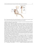
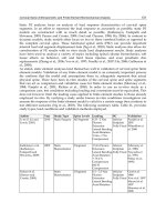
Fig. 1.12. When standing or in the stance phase of walking or running, there is a bending
strength applied on the femoral neck. This strength creates an intense compressive strength
on the lower femoral neck and a tensive strength on the upper femoral neck (see A above).
When the medial gluteus constricts, the compressive strength is increased; and the tensile
strength is decreased (B above). That reduces the potential for injury, since there is greater
probability of injury with tension. Bankoff (2007, p. 128).
Tensio
n
Com
p
ressio
n
Tensio
n
Com
p
ressio
n
A
B
Biomechanical Characteristics of the Bone
75
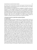
Fig. 1.13. Fig. (A) When tensive strengths are applied on the skeletal system, the bone is
strengthened in the direction of traction while the collagen fibers align with the traction of
the tendon or ligament. (B) Tensive strengths are also responsible for the development of
apophyses, which are bony growths such as processes, tubers or tuberosities. Bankoff (2007,
p. 128).
The bone responds to the demands placed on it as described by Wolff's Law already
mentioned. Thus, different bones and different sections in a bone will respond differently to
compressive and tensive strengths. For example, tibia and femur participates in support
weight in lower limb and are strongest when the load is coming from a compressive
strength. The fibula does not participate significantly in supporting weight, but it is a
muscle insertion site, is stronger when tensive strengths are applied. (Hamil & Knutzen,
1999; Bankoff, 2007).
An assessment of the differences that can be found in the femur showed higher tensive
strength capacity of the middle slope of the body that is loaded by a bending strength in the
supporting weight. In the femur neck, the bone may withstand large compressive strengths,
and in the insertion sites of muscles, there is great tensive strength. (Hamil & Knutzen, 1999;
Bankoff, 2007).
Shear strengths — A shear strength is applied parallel to the surface of an object, creating
internal deformation in an angular direction (FIGURE 1.9 A and B). Maximum shear stresses
act on the surface parallel to the plane of applied strength. The shear stresses are created
when a bone is subjected to compressive strengths, tensive strength or both. FIGURE 1.16
shows how a shear stress is developed by applying a compressive or tensile strength.
Observe and change the shape of the diamond. As the diamond undergoes distortion by
B A
Patellar Li
g
ament
Tensile
Strength
Tibial
Tuberosity
Human Musculoskeletal Biomechanics
76
compression or tension, a shear strength applied to the surface occurs. (Riegger, 1985;
Bankoff, 2007).
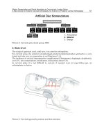
Fig. 1.14. Fractures with avulsion may occur because of tension applied by a tendon or
ligament. The sites of injury in which the fracture with avulsion occur in the pelvic region,
are shown above and include: (A) anterosuperior spine, (B) anteroinferior spine, (C) ischial
tuberosity, (D) pubic bone, and (E) lesser trochanter. Bankoff (2007, p. 129).
A-Avulsion of the lumbar
quadrate muscle
B-Avulsion of the
Sartorius muscle
D-Avulsion of the
adductor muscle
C-Avulsion of the
hamstring muscle
E-Avulsion of the iliopsoas
muscle
Biomechanical Characteristics of the Bone
77
Fig. 1.15. Relation of overload versus distension idealized of a cortical bone subjected to
tension loads (a) and compression (b). Bankoff (2007, p. 129).
Fig. 1.16. Shear stress and distension accompanies both, tensive and compressive loads.
Bankoff (2007, p. 130).
Distension (ε)
ε end
Plastic
Module
Elastic
Module
σ end
σ failed
ε failed
σ end
A
B
Unload
Com
p
ressio
n
Tension
Overload (σ)
Human Musculoskeletal Biomechanics
78
The bone fails more quickly when exposed to a shear strength rather than a compressive or
tensive strength. This is because the bone is anisotropic and responds differently when it
receives loads of different directions. (Riegger, 1985; Bankoff, 2007).
The shear strengths are responsible for problems in the vertebral discs. A shear strength
may produce spondylolisthesis, in which one vertebra slips over another previously. In the
lumbar spine, shear strength by vertebrae, increases with increasing lordosis and with
hyperlordosis. The pull of muscle on the lumbar vertebrae also creates an increasing shear
strength on the vertebrae. (Bankoff, 2007).
Examples of fractures due to shear strengths are frequently found in the femoral condyles or
tibial plateau. The injury mechanism of both is usually a hyperextension of the knee with
some fixing of the foot and a valgus strength or medial on the thigh or shin. In adults, this
shear strength may create a fracture or injury in the collateral or crossed ligaments. In the
developing child, this shear strength may create epiphyseal fractures, such as the distal
femoral epiphysis. The mechanism of injury and resultant epiphyses injury.
Fig. 1.17. An epiphyseal fracture of the distal epiphysis is usually created by a shearing
strength. A strength applied in valgus on the thigh or shin with the foot fixed and
hyperextended knee is commonly produced. Bankoff (2007, p. 130).
are shown in FIGURE 1.17. The effects of such a fracture can be quite significant since that
epiphysis is the fastest growing in the body and is responsible for approximately 37% of
bone growth in the leg. (McConkey & Meeuwisse, 1988; Holich, 1998; Bankoff, 2007).
It is usual the bone is loaded with different types of strength at the same time. FIGURES 1.18
and 1.19 contain an examination of multiple loads absorbed by the tibia during walking and
Fractured growth plate
Valgum Strength
Biomechanical Characteristics of the Bone
79
running, respectively. In the walking, there is a compressive stress on the heel contact,
created by the weight-bearing, ground contact and muscle contraction. Tensive stress
dominates in the middle phase of support because of muscle contraction. It develops a
compressive stress in preparation for propulsion, as it increases the strength on the ground
and muscle contractions. A shear strength is also present in the propulsive phase of support,
and is believed to be related to torsion created by external rotation of the tibia. (Holich, 1998)
In the running, stress increases substantially, and stress patterns are different from those
seen in the walking. There are similarities in support phase of foot, since it creates a
compressive strength due to contact with the ground, body weight and muscle contraction.
This is followed by a great tensive continuous stress throughout the withdrawal phase of
the toes and balancing phase. (Holich, 1998)
Fig. 1.18. Tensive stress, compressive stress and with shear on the tibia of the adult during
the walking - HC = heel contact; FR = foot rectification; HO = heel output; TO = toes output;
B = balancing. Bankoff (2007, p. 131).
The pattern of shear stress is also different, and is representative of the twist created in
response to internal and external rotation of the tibia. Compressive strengths, tensive and
shear applied simultaneously on the bone are important in the development of the bones
strength. FIGURE 1.20 illustrates both the compressive stress lines as tensive in the tibia and
femur during the running. The bone strength is developed along these lines of stress.
(Holich, 1998).
Human Musculoskeletal Biomechanics
80
Bending Strengths — A bending strength is the strength applied to an area that has no
support offered by the framework. When a bone is subjected to a bending strength and
deformation occurs, one side of the bone will form a convexity in which will have tensive
strengths, and the other side of the bone, will form a concavity in which compressive
strengths are present (FIGURE 1.9 A and B). Typically, the bone will fail and break on the
convex side in response to high tensive strengths since the bone may withstand greater
compressive strengths than tensive. The magnitude of tensive and compressive strengths
produced by bending becomes larger the farther away one is the axis of the bone, so they are
larger in the outer portions of the bone. (Holich, 1998; Bankoff, 2007).
Fig. 1.19. Tensive stress, compressive stress and with shear on the tibia of the adult during
the running - TC = toes contact; TO = toes output. Bankoff (2007, p. 131).
Biomechanical Characteristics of the Bone
81
During the regular support, there is bending produced both in the femur and in the tibia.
The femur is tilted both anteriorly and laterally due to the format and mode of transmission
of strength by the supporting weight. The support weight produces an anterior bending in
the tibia. Although these bending strengths are not producers of injury, when one examines
the strength of the tibia and femur, the bone is stronger in those regions in which the
bending strength is greater. (Keller & Spengler, 1989; Jackson, 1990).
Fig. 1.20. Lines of compressive stress (solid line) and Tensive stress (dashed line) are
represented for the distal femur and proximal tibia during the support phase of the running.
Bankoff (2007, p. 131).
Bending loads, generators of injury are produced by application of strength in three or four
points. The application of strength at three points usually involves strengths applied
perpendicularly to the bone at the ends of the bone, with a strength applied in the opposite
direction in the middle of the bone. The bone will break in half as occurs in the fracture in
ski boot shown in FIGURE 1.21. That fracture is produced when the skier falls on top of the
boot with the ski, and the boot pulling the other direction. The bone will break generally in
the back because that is where the convexity is given and where are applied the tensive
strengths. (Keller & Spengler, 1989; Jackson, 1990).
The bending strength in three points is also liable for injuries to the finger, which is
squeezed and forced in hyperextension and knee injuries or lower limb, when the foot is
fixed on the ground and lower body bends. Just eliminating the long supports in footwear of
American football players, and playing in fields in good condition, this type of injury may
be reduced by half. (Keller & Spengler, 1989; Jackson, 1990).
The application of bending strengths at three points can also be used in orthoses. FIGURE
1.22 shows two applications of orthoses using the application of strength at three points for
Human Musculoskeletal Biomechanics
82
a correct postural deviation or stabilize a region. A bending load is applied at four points
with the application of two equal and opposite pairs of strength in each end of the bone. In
the case of four-point bending, the bone will break at the weakest point. This is illustrated in
Figure 1.23 with the application of a bending strength of four points on the femur. The
femur breaks at its weakest point. ( Jackson, 1990).
Fig. 1.21. A bending load at three points creates fracture in ski boots and occurs when the ski
is detained abruptly. A compressive strength is created in the anterior tibia and a tensile
strength is created in the posterior tibia. The tibia fracture is usually on the back. Bankoff
(2007, p. 132).
Torsion Strengths — A torsion strength applied to the bone is a rotational strength, creating a
stress with shear on the material (FIGURE 1.9 A and B). The magnitude of stress increases with
distance from the axis of rotation, and the maximum shear stress acts both perpendicular as
parallel to the axis of the bone. A torsion load also produces tensive and compressive strengths
at the angle through the structure. (Cook et al., 1987; Choi & Goldstein, 1992).
Gregerson, 1971, described that fractures that result from torsion strength occur at the
humerus when imperfect launching techniques create a twist of the arm and lower limb
when the foot is planted and the body changes direction. A spiral fracture is produced
because of applying a torsion strength. An example of the mechanism of a spiral fracture at
the humerus is what happens to a pitcher as shown in FIGURE 1.24. The fracture usually
starts on the outside of the bone and parallel to the middle of the bone. The torsion load on
the lower limb is also responsible for injuries at the cartilage and ligaments in the knee joint.
Injury vs. Load — If a bone will or not suffers an injury because of an applied strength, it
depends on the limits of critical strength of the material and the history of loads received by
the bone. These limits are influenced primarily by the load of the bone can be increased or
decreased by physical activity and conditioning by immobilization and skeletal maturity of
the individual. The speed with which the load is placed is also important because the
response and tolerance are sensitive to it. Loads placed very quickly, when the bone tissue is
unable to deform at the same speed, can cause injury. (Pirnay, 1987).
Tensive
strength
Fracture area
Tensive
strength
Strength
Point of no stress
Strength
Biomechanical Characteristics of the Bone
83
A - Collect Milwaukee B - Collect Jewett
Fig. 1.22. Bending load is used at three points in many types of orthoses. (A) The Milwaukee
brace was used for correction of lateral curvature of the spine and was applied a bending
strength at three points in the column. (B) The Jewett orthosis applies a bending strength at
three points in the thoracic spine to create extension of column in the region. Bankoff (2007,
p. 132).
Fig. 1.23. A bending load in four points applied in a structure will create a break or failure at
the weakest point. Above, it is a hypothetical example using the femur. Bankoff (2007, p.
132).
Strength
Stren
g
th
Stren
g
th
Fracture
Human Musculoskeletal Biomechanics
84
Fig. 1.24. A torsion strength applied to the bone creates a shear stress to the surface. An
example of torsion applied to the humerus is shown above. Bankoff (2007, p. 133).
Muscular activity vs. Load — Muscle activity can also influence in loads that can be
managed by the bones. The muscles change the strengths applied at the bone creating
tensive and compressive strengths. These muscle strengths can reduce tensive strengths or
redistribute the strengths on the bone. Since most bones can withstand large amounts of
compressive strengths, the total amount of load may increase due to the contribution of
muscles. However, if the muscle fatigues during a series of exercises, this decreases its
ability to lighten the load on the bone. The altered distribution of stress or increase in tensile
strengths makes the athlete or player, prone to injury. (Pirnay, 1987).
Stress Fracture — The typical stress fracture occurs during load application, which
produces a shear distension or tension, resulting in lacerations, fractures, ruptures or
avulsions. The bone tissue can also develop a stress fracture in response to compressive or
tensive loads that overwhelm the system, either by a magnitude of excessive strength
applied to one or a few times, or by applying strength in a low or moderate level, but with
an excessive frequency. The relation between the magnitude and frequency of load
applications on the bone . Tolerance of the bone for the injury is a function of load and
cycles of load placement. (McCue, 1970; Matheson, 1987).
Stress fracture occurs when the bone resorption weakens the bone too much and bone
deposit does not occur quickly enough to strengthen the area. The cause of stress fractures at
the lower limb can be attributed to muscle fatigue, which reduces the shock absorption and
allows the redeployment of strengths to specific focal points in the bone. In the upper limb,
the stress fractures are created by repetitive muscular strengths that exert traction on the
Torsion of the
humerus
Shear stress on
bone
Spiral Fracture
Biomechanical Characteristics of the Bone
85
bones. This type of fracture responds for 10% of all injuries in athletes. (McCue, 1970;
Matheson, 1987).
4. Conclusion
The research in bone biomechanics mentioned in this section contributed to show the
importance of this area of study and brought brief discussions on the bone tissue and its
incorporation in the biomechanical aspect of human skeletal and locomotor system. The
information contained in this study by the authors was a cited research and placed the bone
tissue (histology, anatomy, biomechanics and kinesiology) as a material adaptive level of
loads.
5. Acknowledgments
To the researchers cited in this section for scientific contributions on bone biomechanical
considerations:
To the Espaço da Escrita from the University of Campinas for their contribution in the process
of translating the text.
To the Graduate School of Physical Education in particular to Prof. Antonio Carlos de
Moraes.
Prof. Dr. Carlos Aparecido Zamai aid in the development and technical preparation of the
text.
6. References
Alberts, B. et al. (1994). Molecular biology of the cell. Garland Press, 3
rd
ed.
Bankoff, A.D.P. (2007). Morfologia e Cinesiologia Aplicada ao Movimento Humano. Editora
Guanabara Koogan, Rio de Janeiro- Brasil.
Bechtol, C.O. (1954). Grip test. J. Bone Joint Surg., 36-A, 820-824.
Boume, G.H. (editor). (1976). The biochemistry and physiology of bone. 2
nd
ed. 4 vols.
Academic Press.
Choi, K. & Goldstein, S.A. (1992). A comparison of the fatigue behavior of human trabeculae
and cortical bone tissue. Journal Biomechanics, 25: 1371.
Cook, S.D. et al. (1987). Trabeculae bone density and menstrual function in women runners.
The American Journal of Sports Medicine.15: 503.
Egan, J.M. (1987). A constitutive model for the mechanical behavior of soft connective
tissues. Journal of Biomechanics. 20: 681-692.
Fine, K.M.; Vegso, J.J.; Sennett, B., & Torg, J.S. (1991). Prevention of cervical spine injuries in
football. The Physician and Sports Medicine.Vol 19 (10): 54-64.
Gregerson, H.N. (1971). Fractures of the Humerus from Muscular Violence. Acta Orthop.
Scand., 42, 506-512.
Halpbern, B.C., & Smith, A. D. (1991). Catching the cause of low back pain. The Physician
and Sports Medicine. Vol. 19(6): 71079.
Halpbern, B., et al. (1987). High school football injuries: Identifying the risk factors. The
American Journal of Sports Medicine. 15: 316.
Human Musculoskeletal Biomechanics
86
Hamill, J.; & Knutzen, K.M. (1999). Bases biomecânicas do movimento humano. São Paulo:
Manole
Hay, E.D. (editor). (1982). Cell biology of extracellular matrix. Plenum.
Hoffman, A.H.; & Grigg, P. (1989). Measurement of joint capsule tissue loading in the cat
knee using calibrated mechano-receptors. Journal of Biomechanics. 22: 787-791.
Holtrop, M.E. (1975). The ultra structure of bone. Ann Clin Lab Sci, 5:264.
Holick, M.F. (1998). Perspective on the impact of weightlessness on calcium and bone
metabolism. Bone, New York. v.22, n.5, p.105-111.
Jackson, D.L. (1990). Stress fracture of the femur. The Physician and Sports Medicine. v. 9,
(7), pp. 39-44
Junqueira, L.C.; & Carneiro, J. (1999). Histologia básica. 9 ed, Rio de Janeiro: Guanabara
Koogan.
Junqueira, L.C.; & Carneiro, J. (1997). Biologia celular e molecular. 6 ed. Rio de Janeiro:
Guanabara Koogan.
Keller, T.S.; Spengler, D.M. (1989). Regulation of bone stress and strain in the immature and
mature rat femur. Journal of Biomechanics. 22:1115-1127.
Lakes, R.S.; Nakamura, S.; Behiri, J.C. E.; & Bonfield, W. (1990). Fracture mechanics of bone
with short cracks. Journal of Biomechanics. 23:967-975.
Marks Jr, S.C.; & Popoff, S.N. (1988). Bone cell biology the regulation of development
structure, and function in the skeleton. Amer J Anat 183:1.
McConkey, J.P., & Meeuwisse, W. (1988). Tibial plateau fractures in alpine skiing. The
American Journal of Sports Medicine. 16: 159-164.
Matheson, G.O. et al. (1987). Stress fractures in athletes. The American Journal of Sports
Medicine. 15:46-58.
McCue, F.C. (1970). Athletic Injuries of the Proximal Interphalangeal Joint Requiring
Surgical Treatment. J. Bone Joint Surg., 52-A, 937-956.
Mundy, G.R. et al. (1995). The effects of cytokines and growth factors on osteoblastic cells.
Bone. 17:71.
Pirnay, F.M. et al. (1987). Bone mineral contend and physical activity. International Journal
Sport Medicine, 8: 331.
Riegger, C.L. (1985). Mechanical properties of bone. Ln: Orthopaedic and Sports Physical
Therapy. Edited by J.A. Gouldand G.J. Davies. St. Louis, C.V. Mosby Co, 3-49.
Schaffler, M.B.; & Burr, D.B. (1988). Stiffness of compact bone: Effects of porosity and
density. Journal of Biomechanics. 21:13-16.
Shipman, P., Walker, A.; & Bichell, D. (1985). The Human Skeleton. Cambridge, Harvard
University Press.
5
Biomechanical Studies on Hand
Function in Rehabilitation
Sofia Brorsson
Halmstad University, School of Business and Engineering,
Sweden
1. Introduction
Hand function requires interaction of muscles, tendons, bones, joints and nerves. The
unique construction of the hand provides a wide range of important functions such as
manipulation, sense of touch, communication and grip strength (Schieber and Santello
2004). The hand is used in many ways, and in many different situations in our daily lives; so
injuries, diseases or deformities of the hand can affect our quality of life. Several of our most
common injuries and diseases affect hand function. Therefore, it is very important to
understand how healthy and diseased hands work in order to be able to design optimal
rehabilitation strategies pursuant to hand injury or disease.
There are many different methods used today for evaluating hand and finger functions. One
widely accepted method that provides an objective index of the hand and finger functions is
hand force measurement (Balogun, Akomolafe et al. 1991; Innes 1999; Incel, Ceceli et al.
2002). There is also a potential for using modern non-invasive methods such as ultrasound
and finger extension force measurements, but these have not been completely explored so
far.
An important factor in developing grip force is the synergy between the flexor and extensor
muscles. The extensor muscles are active when opening the hand, which is necessary for
managing daily activities (Fransson and Winkel 1991). Even though the extensor muscles are
important for optimal hand function, surprisingly little attention has been focused on these
muscles. It has, however, been difficult to evaluate hand extension force, since there is no
commercially available measurement instrument for finger extension force. In addition,
because of the lack of a device to assess extension force, there is limited basic knowledge
concerning different injuries and how diseases affect the static and dynamic forearm muscle
architecture or/and muscle interaction.
Impaired grip ability in certain diseases such as Rheumatoid Arthritis (RA) could be caused
by dysfunctional extensor muscles leading to inability to open the hand (Neurath and Stofft
1993; Vliet Vlieland, van der Wijk et al. 1996; Bielefeld and Neumann 2005; Fischer,
Stubblefield et al. 2007). Deformities of the MCP-joints are common, and may lead to flexion
contractures and ulnar drift of the fingers. Weak extensor muscles may play a role in the
development of these hand deformities. Furthermore, knowledge concerning how the
muscles are influenced by RA and the mechanism of muscle force impairments is not fully
understood for RA patients. This group of patients would benefit from further hand/finger
Human Musculoskeletal Biomechanics
88
evaluation methods for evaluation of rehabilitation and interventions. There is also a need
for further knowledge of the dynamic action of skeletal muscle and the relation between
muscle morphology and muscle force. The force that can be generated is dependent on the
muscle architecture; these architectural parameters can be studied non-invasively with US.
By using US it is possible to obtain detailed, dynamic information on the muscle
architecture. In order to assess how disease influences muscle morphology and function, it is
necessary to establish baseline knowledge concerning normal forearm muscles. The general
aim of this book chapter was to further our knowledge about biomechanics of the hand, RA
patient, non-invasive evaluation methods used for evaluation of rehabilitation interventions
and muscle biomechanics will be further presented.
2. Biomechanics of the hand
It is important to understand the biomechanics of the hands and fingers as well as the
muscle architecture and structure in order to develop new evaluation methods for finger
extension force. The construction of the hand is quite complicated, including 29 joints, 27
bones and more than 30 muscles and tendons working together for range of motion (ROM),
performing perception and force production.
2.1 The construction of the hand
The metacarpophalangeal (MCP) joints II-V are condyloid joints that allow for movement in
two planes, flexion/extension or adduction/abduction. The ROM in the joints is
approximately 30–40 degrees extension, 70–95 degrees flexion and 20 degrees
adduction/abduction. Ligaments connect the bones and provide stability of the joints; in the
hand there are numerous ligaments that stabilize the joints. To provide stability to the
metacarpal bones, there are ligaments working in conjunction with a thick tissue located in
the palm (the palmar aponeurosis). Muscles that control the hand and have their origin
located near the elbow are called the extrinsic muscles. The tendons of these muscles cross
the wrist and are attached to the bones of the hand. The large muscles that bend (flex) the
fingers originate from the medial aspect of the elbow. The large muscles that straighten
(extend) the fingers originate from the lateral aspect of the elbow. The extrinsic muscles are
responsible for powerful grip ability. In addition to these large muscles, there are smaller
muscles in the hand, intrinsic muscles, that flex, extend, abduct (move outwards) and
adduct (move inwards). The agonist for extension in fingers II–V is the muscle extensor
digitorum communis (EDC). This muscle originates at the lateral epicondyle of humerus;
the muscle is connected to phalanges II–V by four tendons, which glide over the MCP-joints
articulations. The tendons divide into three parts. The main part is attached to the extensor
hood and two collateral ligaments are attached at the lateral and medial parts of the fingers.
The extensor hood covers the whole phalange and is formed from the extensor digitorum
tendon and fibrous tissue. The extension ability in the MCP-, proximal interphalangeal-, and
distal interphalangeal joints are produced by EDC, interossei and lumbricales muscles
(Smith 1996; Marieb 1997). Finger extension force is dependent on the wrist position.
However, at the present time there is no consensus for the optimal wrist angle for finger
extension force measurement. Researchers believe that a wrist position between 10-30
degrees is suitable for finger extension measurements (Li 2002).
Biomechanical Studies on Hand Function in Rehabilitation
89
2.2 Muscle force
The forces a muscle can produce depend on many factors such as the muscles’ structure,
muscle architecture, muscle-nerve interaction and physiological aspects. This thesis focuses
mainly on how the muscle structure, at macro level, affects the forces produced. A brief
overview of the micro architecture level and muscle control is described in this chapter.
The skeletal muscles have four behavioral properties, extensibility, elasticity, irritability and
the ability to develop tension. Extensibility and elasticity provide muscles the ability to
stretch or to increase in length and to return to normal length after stretching and these
properties provide a smooth transmission of tension from muscle to the bones. The muscle’s
ability to respond to stimuli, irritability, provides the capability to develop tension. The
tension that muscles provide has also been referred to as contraction, or the contractile
component of muscle function. The tension that a muscle can develop affects the magnitude
of the force generated, the speed, and length of time that the force is maintained; all these
parameters are influenced by the muscle architecture and function of the particular muscle.
The manner in which the muscles are constructed and controlled contributes to muscle force
production. The force that a muscle generates is also related to the velocity of muscle
shortening, such as the force-velocity relationship, length-tension relationship, stretch-
shortening cycle and electromechanical delay (Wickiewicz, Roy et al. 1984; Brand 1993; Fitts
and Widrick 1996; Kanehisa, Ikegawa et al. 1997; Debicki, Gribble et al. 2004; Hopkins,
Feland et al. 2007).
2.2.1 Macro-architecture
Muscle architecture has been studied by muscle-imaging techniques such as magnetic
resonance imaging and ultrasound (US), and research has shown that there are numerous
variations in the muscle architecture (i.e. fibre length, pennation angle, cross-sectional area
(CSA), muscle volume etc.) within and between species. The architecture of a skeletal
muscle is the macroscopic arrangement of the muscle fibres. These are considered relative to
the axis of force generated (Otten 1988; Blazevich and Sharp 2005). The arrangements of
muscle fibres affect the strength of muscular contraction and the ROM which a muscle
group can move a body segment. It is important to understand the impact of muscle
architecture parameters in order to design effective interventions for disease, injury
rehabilitation, as well as for athletic training and exercise, especially considering the results
of adaptation to physical training. The pennation angle is the angle between the muscle fibre
and the force generating axis (Figure 1). Early researchers have reported greater pennation
angles in subjects that practice weight training compared to untrained subjects. It has been
claimed that increase in pennation angle is biomechanically important since more tissue can
attach to a given area of tendon, and slower rotation of the muscle fibre during contraction
is possible through a greater displacement of the tendon, thus generating more force
(Aagaard, Andersen et al. 2001; Kawakami, Akima et al. 2001).
Fascicle length (muscle fibre) can be of importance for the biomechanics of the muscles, the
change in fascicle length has been reported to have impact on high-speed force generation
(Fukunaga, Ichinose et al. 1997). The fascicles containing a greater number of sarcomeres in
series and generate force over longer ranges of motion and longer fibres also possess greater
shortening speeds. From experimental studies, it has been claimed that the physiological
cross-sectional area (PCSA) of a muscle is the only architectural parameter that is directly
proportional to the maximum tetanic tension generated by the muscle. Theoretically, the
Human Musculoskeletal Biomechanics
90
PCSA represents the sum of all CSA of the muscle fibres inside the muscle. The design of the
muscles in terms of pennation angle, fibre length and PCSA reflects the muscles’ capacity to
develop force. Although each muscle is unique in architectural design, a number of
generalizations have been made on the lower extremity muscles. For example quadriceps
muscles are designed with high pennation angles, large PCSA and short muscle fibres, and
this design is suitable for large force production. The same design pattern can be observed
in the upper extremity, and the flexor muscles structure predicts that they generate almost
twice the force as the extensor muscles (Lieber and Friden 2000). To summarize: the research
about muscle architecture and adaptation to speed and strength exercises shows that muscle
architecture is plastic and can respond to exercise, although more research is required to
fully understand the impact of varying methods of strength and speed training. To fully
understand the adaptation of muscle architecture to all forms of interventions would require
a formidable research effort. Surprisingly little research has described changes of muscle
architecture when aging, despite that aging is associated with significant sarcopenia.
Fig. 1. (A) The black rectangle shows the position of the US probe during pennation angle
measurements of the m.EDC. (B) The longitudinal US image showing the superficial
aponeurosis (black arrows), the deep aponeurosis (white arrows) and the pennation angle
(α). ©Sofia Brorsson
Previous research has claimed that pennation angle and fascicle length were significantly
smaller in older than younger individuals in some muscles such as m. soleus, m.
gastrocnemius medialis and lateralis (Kubo, Kanehisa et al. 2003; Narici, Maganaris et al.
2003; Morse, Thom et al. 2005), but there were no age related changes in m. triceps brachii
and m. gastrocnemius medialis concerning pennation angles for women (Kubo, Kanehisa et
al. 2003).Furthermore, little research has been done concerning how muscle architecture
adapts to disuse or diseased muscles, which is very important from a rehabilitation
perspective. Kawakami et al. (2000) investigated changes in the muscle parameters fascicle