Advances in Mechatronics Part 1 doc
Bạn đang xem bản rút gọn của tài liệu. Xem và tải ngay bản đầy đủ của tài liệu tại đây (673.95 KB, 20 trang )
ADVANCESIN
MECHATRONICS
EditedbyHoracioMartínez‐Alfaro
Advances in Mechatronics
Edited by Horacio Martínez-Alfaro
Published by InTech
Janeza Trdine 9, 51000 Rijeka, Croatia
Copyright © 2011 InTech
All chapters are Open Access articles distributed under the Creative Commons
Non Commercial Share Alike Attribution 3.0 license, which permits to copy,
distribute, transmit, and adapt the work in any medium, so long as the original
work is properly cited. After this work has been published by InTech, authors
have the right to republish it, in whole or part, in any publication of which they
are the author, and to make other personal use of the work. Any republication,
referencing or personal use of the work must explicitly identify the original source.
Statements and opinions expressed in the chapters are these of the individual contributors
and not necessarily those of the editors or publisher. No responsibility is accepted
for the accuracy of information contained in the published articles. The publisher
assumes no responsibility for any damage or injury to persons or property arising out
of the use of any materials, instructions, methods or ideas contained in the book.
Publishing Process Manager Mia Devic
Technical Editor Teodora Smiljanic
Cover Designer Jan Hyrat
Image Copyright Tonis Pan, 2010. Used under license from Shutterstock.com
First published August, 2011
Printed in Croatia
A free online edition of this book is available at www.intechopen.com
Additional hard copies can be obtained from
Advances in Mechatronics, Edited by Horacio Martínez-Alfaro
p. cm.
ISBN 978-953-307-373-6
free online editions of InTech
Books and Journals can be found at
www.intechopen.com
Contents
Preface IX
Part 1 Automatic Control and Artificial Intelligence 1
Chapter 1 Integrated Control of
Vehicle System Dynamics: Theory and Experiment 3
Wuwei Chen, Hansong Xiao, Liqiang Liu,
Jean W. Zu and HuiHui Zhou
Chapter 2 Integrating Neural Signal
and Embedded System for Controlling Small Motor 31
Wahidah Mansor, Mohd Shaifulrizal Abd Rani
and Nurfatehah Wahy
Chapter 3 Artificial Intelligent Based Friction Modelling
and Compensation in Motion Control System 43
Tijani Ismaila B., Rini Akmeliawati and Momoh Jimoh E. Salami
Chapter 4 Mechatronic Systems for Kinetic Energy
Recovery at the Braking of Motor Vehicles 69
Corneliu Cristescu, Petrin Drumea, Dragos Ion Guta,
Catalin Dumitrescu and Constantin Chirita
Chapter 5 Integrated Mechatronic Design
for Servo Mechanical Systems 109
Chin-Yin Chen, I-Ming Chen and Chi-Cheng Cheng
Part 2 Robotics and Vision 129
Chapter 6 On the Design of Underactuated
Finger Mechanisms for Robotic Hands 131
Pierluigi Rea
Chapter 7 Robotic Grasping and Fine
Manipulation Using Soft Fingertip 155
Akhtar Khurshid, Abdul Ghafoor and M. Afzaal Malik
VI Contents
Chapter 8 Recognition of Finger Motions for
Myoelectric Prosthetic Hand via Surface EMG 175
Chiharu Ishii
Chapter 9 Self-Landmarking for Robotics Applications 191
Yanfei Liu and Carlos Pomalaza-Ráez
Chapter 10 Robotic Waveguide by Free Space Optics 207
Koichi Yoshida, Kuniaki Tanaka and Takeshi Tsujimura
Chapter 11 Surface Reconstruction of Defective
Point Clouds Based on Dual Off-Set Gradient Functions 223
Kun Mo and Zhoupin Yin
Part 3 Other Applications and Theory 245
Chapter 12 Advanced NO
x
Sensors for Mechatronic Applications 247
Angela Elia, Cinzia Di Franco, Adeel Afzal,
Nicola Cioffi and Luisa Torsi
Chapter 13 Transdisciplinary Approach of the
Mechatronics in the Knowledge Based Society 271
Ioan G.Pop and Vistrian Mătieş
Preface
The community of researchers claiming the relevance of their work to the field of
mechatronicsisgrowingfasterandfaster,despitethefactthatthetermitselfhasbeen
inthescientificcommunityformorethan40years.Numerousbookshavebeenpub‐
lishedspecializingin anyoneofthewellkn
own areas that comprised it:mechanical
engineering,electroniccontrolandsystems,butattemptstobringthemtogetherasa
synergisticintegratedareasarescarce.Yetsomecommonapplicationareasclearlyap‐
pearsincethen.
Thegoalofthisbookistocollectstate‐of‐the‐artcontributionsthatdiscussrecentde‐
velopmentsthatshowmoremoresy
nergisticintegrationamongtheareas.Thebookis
dividedinthreesectionswithoutandspecificspecialorder.Thefirstsectionisabout
AutomaticControlandArtificialIntelligencewithfivechapters,thesecondsectionis
RoboticsandVisionwithsixchapters,andthethirdsectionisOtherA
pplicationsand
Theorywithtwochapters.
The first chapter on Automatic Control and Artificial Intelligence by Wuwei Chen,
HansongXiao,LiqiangLiu,JeanW.Zu,andHuiHuiZhouissometheoryandexperi‐
ments of integrated control vehicle dynamics. The second chapter by Wahidah
Mansor,SaifulrizalAbRani,andNu
rfatehahWahiis about integratingneuralsignal
and embedded system for controlling a small motor. Ismaila B. Tijani, Akmeliawati
Rini, and Jimoh E. Salami Momoh inthe third chapter shows anartificial intelligent
based friction modelling and compensation for motion control system. The fourth
chapter by Corneliu Cristescu, Petrin Drumea, Dragos Ion Guta, and Catalin Dumi‐
trescuisaboutamechatronicsy
stemsforkineticenergyrecoveryatthebrakingofmo‐
torvehicles.ThefifthchapterandlastofthissectionbyChin‐YinChen,I‐MingChen,
and Chi‐Cheng Cheng is about integrated mechatronic design for servo‐mechanical
sy
stems.
FortheRoboticsandVisionsection,thefirstchapteris onthedesi gnofunderactuat‐
edfingermechanismsforrobotichandsbyPierluigiRe a. Thefollowingchapterby
AkhtarKhurshiddealswithroboticgraspingandfinemanipulationusingsoftfinger‐
tip.Inthenextchapter,ChiharuIshiitalksaboutrecognitionoffingermotionsformy‐
oelectric prosthetic hand via surface EMG. Yanfei Liu and Carlos Pomalaza‐Ráez in
thefollowingchaptertalksaboutself‐landmarkingforroboticsapplications.Thenext
X Preface
chapter is about robotic waveguide by free space optics by Koichi Yoshida, Kuniaki
Tanaka,andTakeshiTsujimura.AndthelastchapterforthissectionbyKunMoand
Zhoupin Yin is aboutsurface reconstruction of defective point clouds based ondual
off‐setgradientfunctions.
FortheOtherApplicationsandTheorysec
tion,thefirstchapterbyAngelaElia,Cinzia
DiFranco,AdeelAfzal,NicolaCioffiandLuisaTorsiisaboutadvancedNOxsensors
formechatronicapplications.ThelastchapterbutnottheleastbyIoanG.PopandVis‐
trian Mătieş is about a transdisciplinary approach of the mechatronics in the
knowledgebasedsoc
iety.
Idohopeyouwillfindthebookinterestingandthoughtprovoking.Enjoy!
HoracioMartínez‐Alfaro
MechatronicsandAutomationDepartment,
TecnológicodeMonterrey,Monterrey,
México
July2011
Part 1
Automatic Control and Artificial Intelligence
1
Integrated Control of Vehicle System Dynamics:
Theory and Experiment
Wuwei Chen
1
, Hansong Xiao
2
, Liqiang Liu
1
,
Jean W. Zu
2
and HuiHui Zhou
1
1
Hefei University of Technology,
2
University of Toronto,
P. R. China
Canada
1. Introduction
Modern motor vehicles are increasingly using active chassis control systems to replace
traditional mechanical systems in order to improve vehicle handling, stability, and comfort.
These chassis control systems can be classified into the three categories, according to their
motion control of vehicle dynamics in the three directions, i.e. vertical, lateral, and
longitudinal directions: 1) suspension, e.g. active suspension system (ASS) and active body
control (ABC); 2) steering, e.g. electric power steering system (EPS) and active front steering
(AFS), and active four-wheel steering control (4WS); 3) traction/braking, e.g. anti-lock brake
system (ABS), electronic stability program (ESP), and traction control (TRC). These control
systems are generally designed by different suppliers with different technologies and
components to accomplish certain control objectives or functionalities. Especially when
equipped into vehicles, the control systems often operate independently and thus result in a
parallel vehicle control architecture. Two major problems arise in such a parallel vehicle
control architecture. First, system complexity in physical meaning comes out to be a
prominent challenge to overcome since the amount of both hardware and software increases
dramatically. Second, interactions and performance conflicts among the control systems
occur inevitably because the vehicle motions in vertical, lateral, and longitudinal directions
are coupled in nature. To overcome the problems, an approach called integrated vehicle
dynamics control was proposed around the 1990s (Fruechte et al., 1989). Integrated vehicle
dynamics control system is an advanced system that coordinates all the chassis control
systems and components to improve the overall vehicle performance including safety,
comfort, and economy.
Integrated vehicle dynamics control has been an important research topic in the area of
vehicle dynamics and control over the past two decades. Comprehensive reviews on this
research area may refer to (Gordon et al., 2003; Yu et al., 2008). The aim of integrated vehicle
control is to improve the overall vehicle performance through creating synergies in the use
of sensor information, hardware, and control strategies. A number of control techniques
have been designed to achieve the goal of functional integration of the chassis control
systems. These control techniques can be classified into two categories, as suggested by
(Gordon et al., 2003): 1) multivariable control; and 2) hierarchical control. Most control
Advances in Mechatronics
4
techniques used in the previous studies fall into the first category. Examples include
nonlinear predictive control (Falcone et al., 2007), random sub-optimal control (Chen et al.,
2006), robust
H
(Hirano et al., 1993), sliding mode (Li et al., 2008), and artificial neural
networks (Nwagboso et al., 2002), etc. In contrast, hierarchical control has not yet been
applied extensively to integrated vehicle control system. It is indicated by the relatively
small volume of research publications (Gordon et al., 2003; Gordon, 1996; Rodic and
Vukobratovie, 2000; Karbalaei et al., 2007; He et al., 2006; Chang and Gordon, 2007;
Trächtler, 2004). In the studies, there are two types of hierarchical control architecture: two-
layer architecture (Gordon et al., 2003; Gordon, 1996; Rodic and Vukobratovie, 2000;
Karbalaei et al., 2007; He et al., 2006) and three-layer architecture (Chang and Gordon, 2007;
Trächtler, 2004). For instance in (Chang and Gordon, 2007), a three-layer model-based
hierarchical control structure was proposed to achieve modular design of the control
systems: an upper layer for reference vehicle motions, an intermediate layer for actuator
apportionment, and a lower layer for stand-alone actuator control.
In the review of the past studies on integrated vehicle dynamics control, we address the
following two aspects in this study. First, hierarchical control has been identified as the
more effective control technique compared to multivariable control. In addition to
improving the overall vehicle performance including safety, comfort, and economy,
application of hierarchical control brings a number of benefits, among which: 1) facilitating
the modular design of chassis control systems; 2) mastering complexity by masking the
details of the individual chassis control system at the lower layer; 3) favoring scalability; and
4) speeding up development processes and reducing costs by sharing hardware (e.g.
sensors). Second, most of the research activities on this area were focused solely on
simulation investigations. There have been very few attempts to conduct experimental
study to verify the effectiveness of those proposed integrated vehicle control systems.
However, the experimental verification is an essential stage in developing those integrated
vehicle control systems in order to transfer them from R&D activities to series production.
In this chapter, a comprehensive and intensive study on integrated vehicle dynamics control
is performed. The study consists of three investigations: First, a multivariable control
technique called stochastic sub-optimal control is applied to integrated control of electric
power steering system (EPS) and active suspension system (ASS). A simulation
investigation is performed and comparisons are made to demonstrate the advantages of the
proposed integrated control system over the parallel control system. Second, a two-layer
hierarchical control architecture is proposed for integrated control of active suspension
system (ASS) and electronic stability program (ESP). The upper layer controller is designed
to coordinate the interactions between the ASS and the ESP. A simulation investigation is
conducted to demonstrate the effectiveness of the proposed hierarchical control system in
improving vehicle overall performance over the non-integrated control system. Finally, a
hardware-in-the-loop (HIL) experimental investigation is performed to verify the simulation
results.
2. System model
In this study, two types of vehicle dynamic model are established: a non-linear vehicle
dynamic model developed for simulating the vehicle dynamics, and a linear 2-DOF
reference model used for designing controllers and calculating the desired responses to
driver’s steering input.
Integrated Control of Vehicle System Dynamics: Theory and Experiment
5
2.1 Vehicle dynamic model
A vehicle dynamic model is established and the three typical vehicle rotational motions,
including yaw motion, pitch motion, and roll motion, are considered. They are illustrated in
Fig. 1(a), Fig. 1(b), and Fig. 1(c), respectively. In the figures, we denote the front-right wheel,
front-left wheel, rear-right wheel, and rear-left wheel as wheel 1, 2, 3, and 4, respectively.
The equations of motion can be derived as:
For yaw motion of sprung mass shown in Fig. 1(a)
12 34
()()
zz xz y y y y
IIaFFbFF
(1)
And the equations of motion in the longitudinal direction and the lateral direction can be
written as
1234
()
xyz sz x x x x r
mv v mh F F F F
f
m
g
(2)
1234
()
y
xz s
yyyy
mv v mh F F F F
(3)
For pitch motion of sprung mass shown in Fig. 1(b)
34 12
()()
y
zz zz
IbFFaFF
(4)
And for roll motion of sprung mass shown in Fig. 1(c)
2314
() ( )
xsyxzxzzs zzzz
ImvvhI m
g
hFFFFd
(5)
1y
F
4y
F
1x
F
4x
F
f
3x
F
3y
F
2x
F
2y
F
v
y
x
v
a
b
GC
(a) (b) (c)
Fig. 1. Three typical vehicle rotational motions: (a) yaw motion; (b) pitch motion; (c) roll
motion.
We also have the equations for the vertical motions of sprung mass and unsprung mass
1234ss z z z z
mz F F F F
(6)
()
ui ui ti
g
iui zi
mz k z z F
(i=1,2,3,4) (7)
where
21
1 111111 1
()
()()[ ]
22
af
uu
z sus us
k
zz
Fkzz czz
f
dd
(8)
Advances in Mechatronics
6
21
2222222 2
()
()()[ ]
22
af
uu
z sus us
k
zz
Fkzz czz
f
dd
(9)
34
3333333 3
()
()()[ ]
22
ar u u
z sus us
kzz
Fkzz czz f
dd
(10)
34
4444444 4
()
()()[ ]
22
ar u u
z sus us
kzz
Fkzz czz
f
dd
(11)
When the pitch angle of sprung mass
and the roll angle of sprung mass
are small, the
following approximation can be reached
dazz
ss
1
(12)
dazz
ss
2
(13)
dbzz
ss
3
(14)
dbzz
ss
4
(15)
Considering the rotational dynamics of the wheel of the vehicle shown in Fig. 2, the
equation of motion is derived as
(1,4)
wi xwiw i
IFRTi
(16)
i
i
T
w
R
x
wi
F
zwi
F
Fig. 2 Wheel dynamic model.
It is noted that the longitudinal and lateral forces acting on the i-th wheel,
xi
F and
y
i
F , have
the following relationships with the tyre forces along the wheel axes,
xwi
F and
y
wi
F , because
of the steering angle of the i-th wheel
i
,
cos sin
(1,,4)
sin cos
xi xwi
ii
yi ywi
ii
FF
i
FF
(17)
Integrated Control of Vehicle System Dynamics: Theory and Experiment
7
For simplicity, the steering angles are assumed as:
12
f
, and
34r
.
It is worthy to mention that: 1) for the above-mentioned first investigation, both the ASS
controller and EPS controller are designed respectively. Eq. 4 through Eq. 15 are used to
develop the ASS controller, while the other equations are employed to design the EPS
controller; 2) for the second investigation, the same set of equations, i.e. Eq. 4 through Eq. 15,
is used to design the ASS controller. While for the ESP controller, the yaw motion of sprung
mass described in Eq. 1 is replaced by the following equations of motion.
For yaw motion of sprung mass
12 34
()()
zz xz
yy yy
zc
IIaFFbFFM
(18)
where
zc
M
is the corrective yaw moment generated by the ESP controller, which is given as
1324
()
zc xxxx
M
dF F F F
(19)
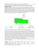
2.2 EPS model
The major components of a rack-pinion EPS as shown in Fig. 3 consist of a torque sensor, a
control unit (ECU), a motor, and a gear assist mechanism. The torque sensor measures the
torque from the steering wheel and sends a signal to the ECU. The ECU also receives
steering position signal from a position sensor and the vehicle speed signal. These signals
are processed in the ECU and an assist command is generated. The command is in turn
given to the motor, which provides the torque to the gear assist mechanism. The torque is
amplified by the gear mechanism and the amplified torque is applied to the steering
column, which is connected to the rack-pinion mechanism.
Fig. 3. EPS system.
The following governing equations for the pinion can be obtained by applying force analysis
to the pinion
11pmcre
ITTTc
(20)
where T
c
is the torque applied on the steering wheel, which can be calculated by
Advances in Mechatronics
8
1
()
csh
Tk
(21)
Let the speed reduction ratio of the rack-pinion mechanism be N
2
, we have
12
f
N
(22)
2.3 Tyre model
The Pacejka nonlinear tyre model (Bakker et al., 1987; Pacejka, 2002) is used to determine the
dynamic forces of each tyre i. The inputs of the tyre model include the vertical tyre force,
tyre sideslip angle and tyre slip ratio; and the outputs include the longitudinal tyre force
xwi
F , lateral tyre force
y
wi
F
and self-aligning torque
zwi
T . The Pacejka’s magic formula is
presented as
0
(/)
xwi x x
FF
(23)
0
(/)
y
wi
yy
FF
(24)
1
sin tan ( )
zwi z z z z
TD C B
(25)
where
zwi
T is the aligning torque acting on the tyre; and
1
0
sin tan ( )
xx x xx
FD C B
(26)
1
0
sin tan ( )
yy y yy
FD C B
(27)
22
x
y
, /(1 )
x
, tan /(1 )
y
(28)
where the coefficients depend on the tyre characteristics and road conditions, the physical
definitions of these coefficients can be found in the references (Bakker et al., 1987; Pacejka,
2002).
2.4 Road excitation model
A filtered white noise signal (Yu and Crolla, 1998) is selected as the road excitation to the
vehicle, which can be expressed as
g0g 0
22 (1,,4)
iii
zfzwGvi
(29)
2.5 2-DOF vehicle rreference model
A 2-DOF linear bicycle model is used as the vehicle reference model to generate the desired
vehicle states in this study since the 2-DOF model reflects the desired relationship between
the driver’s steer input and the vehicle yaw rate. This model is employed for both the upper
layer controller design and the ESP controller design later in the paper. The equations of
motion are expressed as follows by assuming a small sideslip angle and a constant forward
speed.