Advances in Mechatronics Part 8 doc
Bạn đang xem bản rút gọn của tài liệu. Xem và tải ngay bản đầy đủ của tài liệu tại đây (1.22 MB, 20 trang )
Part 2
Robotics and Vision
6
On the Design of Underactuated Finger
Mechanisms for Robotic Hands
Pierluigi Rea
DiMSAT, University of Cassino
Italy
1. Introduction
The mechatronic design of robotic hands is a very complex task, which involves different
aspects of mechanics, actuation, and control. In most of cases inspiration is taken by the
human hand, which is able to grasp and manipulate objects with different sizes and shapes,
but its functionality and versatility are very difficult to mimic. Human hand strength and
dexterity involve a complex geometry of cantilevered joints, ligaments, and
musculotendinous elements that must be analyzed as a coordinated entity. Furthermore,
actuation redundancy of muscles generates forces across joints and tissues, perception
ability and intricate mechanics complicate its dynamic and functional analyses.
By considering these factors it is evident that the design of highly adaptable, sensor-based
robotic hands is still a quite challenge objective giving in a number of cases devices that are
still confined to the research laboratory.
There have been a number of robotic hand implementations that can be found in literature.
A selection of leading hand designs reported here is limited in scope, addressing mechanical
architecture, not control or sensing schemes. Moreover, because this work is concentrated to
finger synthesis and design, the thumb description is excluded, as well as two-fingered
constructions, because most of them were designed to work as grippers and would not
integrate in the frame of multi-finger configuration.
Significant tendon operated hands are the Stanford/JPL hand and the Utah/MIT hand. In
particular, the first one has three 3-DOF fingers, each of them has a double-jointed head
knuckle providing 90° of pitch and jaw and another distal knuckle with a range of ±135°.
The Utah/MIT dextrous hand has three fingers with 4-DOFs, each digit of this hand has a
non anthropomorphic design of the head knuckle excluding circumduction. The inclusion of
three fingers minimizes reliance on friction and adds redundant support to manipulations
tasks. Each N-DOF finger is controlled by 2-N independent actuators and tension cables.
Although these two prototypes exhibit a good overall behaviour, they suffer of limited
power transmission capability.
The prototype of the DLR hand possesses special designed actuators and sensors integrated
in the hand’s palm and fingers. This prototype has four fingers with 3-DOFs each, a 2-DOFs
base joint gives ± 45° of flexion and ±30° of abduction/adduction, and 1-DOF knuckle with
135° of flexion. The distal joint, which is passively driven, is capable of flexing 110°.
A prototype of an anthropomorphic mechanical hand with pneumatic actuation has been
developed at Polytechnic of Turin having 4 fingers with 1-DOF each and it is controlled
through PWM modulated digital valves.
Advances in Mechatronics
132
Following this latter basic idea, several articulated finger mechanisms with only 1-DOF
were designed and built at the University of Cassino and some prototypes allowing to carry
out suitable grasping tests of different objects were developed.
More recently, the concept of the underactuation was introduced and used for the design of
articulated finger mechanisms at the Laval University of Québec.
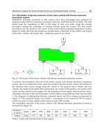
Underactuation concept deals with the possibility of a mechanical system to be designed
having less control inputs than DOFs. Thus, underactuated robotic hands can be considered
as a good compromise between manipulation flexibility and reduced complexity for the
control and they can be attractive for a large number of application, both industrial and non
conventional ones.
2. The underactuation concept
Since the last decades an increasing interest has been focused on the design and control of
underactuated mechanical systems, which can be defined as systems whose number of
control inputs (i.e. active joints) is smaller than their DOFs. This class of mechanical systems
can be found in real life; examples of such systems include, but not limited to, surface
vessels, spacecraft, underwater vehicles, helicopters, road vehicles, and robots.
The underactuation property may arise from one of the following reasons:
the dynamics of the system (e.g. aircrafts, spacecrafts, helicopters, underwater vehicles);
needs for cost reduction or practical purposes (e.g. satellites);
actuator failure (e.g. in surface vessel or aircraft).
Furthermore, underactuation can be also imposed artificially to get a complex low-order
nonlinear systems for gaining an insight in the control theory and developing new
strategies. However, the benefits of underactuation can be extended beyond a simple
reduction of mechanical complexity, in particular for devices in which the distribution of
wrenches is of fundamental importance. An example is the automobile differential, in which
an underactuated mechanism is commonly used to distribute the engine power to two
wheels. The differential incorporates an additional DOF to balance the torque delivered to
each wheel. The differential fundamentally operates on wheel torques instead of rotations;
aided by passive mechanisms, the wheels can rotate along complex relative trajectories,
maintaining traction on the ground without closed loop active control.
Some examples found in Robotics can be considered as underactuated systems such as:
legged robots, underwater and flying robots, and grasping and manipulation robots.
In particular, underactuated robotic hands are the intermediate solution between robotic
hands for manipulation, which have the advantages of being versatile, guarantee a stable
grasp, but they are expensive, complex to control and with many actuators; and robotic
grippers, whose advantages are simplified control, few actuators, but they have the
drawbacks of being task specific, and perform an unstable grasp.
In an underactuated mechanism actuators are replaced by passive elastic elements (e.g.
springs) or limit switches. These elements are small, lightweight and allow a reduction in
the number of actuators. They may be considered as passive elements that increase the
adaptability of the mechanism to shape of the grasped object, but can not and should not be
handled by the control system.
The correct choice of arrangement and the functional characteristics of the elastic or
mechanical limit (mechanical stop) ensures the proper execution of the grasping sequence.
In a generic sequence for the grasping action, with an object with regular shape and in a
fixed position, one can clearly distinguish the different phases, as shown in Fig. 1.
On the Design of Underactuated Finger Mechanisms for Robotic Hands
133
In Fig.1a the finger is in its initial configuration and no external forces are acting. In Fig.1b
the proximal phalanx is in contact with the object. In the Fig.1c the middle phalanx, after a
relative rotation respect to the proximal phalanx, starts the contact with the object. In this
configuration, the first two phalanges can not move, because of the object itself. In Fig.1d,
finally, the finger has completed the adaptation to the object, and all the three phalanges are
in contact with it. A similar sequence can be described for an irregularly shaped object, as
shown in Fig.2, in which it is worth to note the adaptation of the finger to the irregular
object shape.
An underactuated mechanism allows the grasping of objects in a more natural and more
similar to the movement obtained by the human hand. The geometric configuration of the
finger is automatically determined by external constraints related with the shape of the
object and does not require coordinated activities of several phalanges. It is important to
note that the sequences shown in Figs.1 and 2 can be obtained with a continuous motion
given by a single actuator.
Few underactuated finger mechanisms for robotic hands have been proposed in the
literature. Some of them are based on linkages, while others are based on tendon-actuated
mechanisms. Tendon systems are generally limited to rather small grasping forces and they
lead to friction and elasticity. Hence, for applications in which large grasping forces are
a) b) c) d)
Fig. 1. A sequence for grasping a regularly shaped object: a) starting phase; b) first phalange
is in its final configuration; c) second phalange is in its final configuration; d) third phalange
is in its final configuration.
a) b) c) d)
Fig. 2. A sequence for grasping an irregularly shaped object: a) starting phase; b) first
phalange is in its final configuration; c) second phalange is in its final configuration; d) third
phalange is in its final configuration.
Advances in Mechatronics
134
required, linkage mechanisms are usually preferred and this Chapter is focused to the study
of the latter type of mechanisms.
An example of underactuation based on cable transmission is shown in Fig.3a, it consists of
a cable system, which properly tensioned, act in such a way as to close the fingers and grasp
the object.
The underactuation based on link transmission, or linkages, consists of a mechanism with
multiple DOFs in which an appropriate use of passive joints enables to completely envelop
the object, so as to ensure a stable grasp. An example of this system is shown in Fig.3.b. This
type solution for robotic hands has been developed for industrial or space applications with
the aim to increase functionality without overly complicating the complexity of the
mechanism, and ensuring a good adaptability to the object in grasp.
a) b)
c) d)
Fig. 3. Examples of underactuation systems: a) tendon-actuated mechanism; b) linkage
mechanism; c) differential mechanism; d) hybrid mechanism.
On the Design of Underactuated Finger Mechanisms for Robotic Hands
135
A differential mechanism, shown in Fig. 3c, is a device, usually but not necessarily used for
gears, capable of transmitting torque and rotation through three shafts, almost always used
in one of two ways: in one way, it receives one input and provides two outputs, this is found
in most automobiles, and in the other way, it combines two inputs to create an output that is
the sum, difference, or average, of the inputs. These differential mechanisms have unique
features like the ability to control many DOFs with a single actuator, mechanical stops or
elastic limits. The differential gear, commonly used in cars, distributes the torque from the
engine on two-wheel drive according to the torque acting on the wheels. Applying this
solution to robotic hands, the actuation can be distributed to the joints according to the
reaction forces acting to each phalanx during its operation.
Hybrid solutions have been also developed and make use of planetary gears and linkages,
together with mechanical stops or elastic elements. An example is shown in Fig. 3d.
3. Design of underactuated finger mechanism
An anthropomorphic robotic finger usually consists of 2-3 hinge-like joints that articulates
the phalanges. In addition to the pitch enabled by a pivoting joint, the head knuckle,
sometimes also provides yaw movement. Usually, the condyloid nature of the human
metacarpal-phalangeal joint is often separated into two rotary joints or, as in the case under-
study, simplified as just one revolute joint.
Maintaining size and shape of the robot hand consistent to the human counterpart is to
facilitate automatic grasp and sensible use of conventional tools designed for human finger
placement. This holds true for many manipulative applications, especially in prosthesis and
tele-manipulation where accuracy of a human hand model enables more intuitive control to
the slave. Regarding to the actuation system in most of cases adopted solutions do not
attempt to mimic human capabilities, but assume some of the pertinent characteristics of the
force generation, since complex functionality of tendons and muscles that have to be
replaced and somehow simplified by linear or revolute actuators and rotary joints.
The design of a finger mechanism proposed here uses the concept of underactuation applied
to mechanical hands. Specifically, underactuation allows the use of n – m actuators to
control n-DOFs, where m passive elastic elements replace actuators, as shown in Fig. 4.
Thus, the concept of underactuation is used to design a suitable finger mechanism for
mechanical hands, which can automatically envelop objects with different sizes and shapes
through simple stable grasping sequences, and do not require an active coordination of the
phalanges. Referring to Figs. 4 and 5, the underactuated finger mechanism of Ca.U.M.Ha.
(Cassino-Underactuated-Multifinger-Hand) is composed by three links m
j
for j = 1, 2, 3,
which correspond to the proximal, median and distal phalanges, respectively. Dimensions
of the simplified sketch reported in Fig.4 have been chosen according to the overall
characteristics of the human finger given in Table 1. In particular, in Fig. 4, θ
iM
are the
maximal angles of rotation, and torsion springs are denoted by S
1
and S
2
. In the kinematic
scheme of Fig.5, two four-bar linkages A, B, C, D and B, E, F, G are connected in series
through the rigid body B, C, G, for transmitting the motion to the median and distal
phalanges, respectively, where the rigid body A, D, P represents the distal phalange.
Likewise to the human finger, links m
j
( j = 1, 2, 3) are provided of suitable mechanical
stoppers in order to avoid the hyper-extension and hyper-flexion of the finger mechanism.
Both revolute joints in A and B are provided of torsion springs in order to obtain a statically
determined system in each configuration of the finger mechanism.
Advances in Mechatronics
136
P
P
2
P
3
θ
1M
θ
1
θ
2M
θ
2
θ
3
θ
3M
l
2
l
3
l
1
S
1
S
2
Fig. 4. Simplified sketch of underactuated finger mechanism.
Phalanx Length Angle
m
1
l
1
= 43 mm
1M
= 83°
m
2
l
2
= 25 mm
2M
= 105°
m
3
l
3
= 23 mm
3M
= 78°
Table 1. Characteristics of an index human finger.
F
G
C
B
D
A
m
2
1
2
3
P
E
3
2
m
3
m
1
H
I
1
Fig. 5. Kinematic sketch of the underactuated finger mechanism.
3.1 Optimal kinematic synthesis
The optimal dimensional synthesis of the function-generating linkage shown in Fig. 5,
which is used as transmission system from the pneumatic cylinder to the three phalanxes of
On the Design of Underactuated Finger Mechanisms for Robotic Hands
137
the proposed underactuated finger mechanism, is formulated by using the Freudenstein’s
equations and the transmission defect, as index of merit of the force transmission. The three
linkages connected in series are synthesized as in the following by starting from the four-bar
linkage, which moves the third phalanx.
3.1.1 Synthesis of the four bar linkage A, B, C ,D
By considering the four-bar linkage A, B, C , D in Fig. 5, one has to refer to Fig.6 and the
Freudenstein’s equations can be expressed in the form
12 3
cos cos cos( ) 1, 2, 3
ii ii
RR R i
(1)
with
2222
12 22 3 2
/; /; ( )/2RlaRlcR abcl ac
(2)
where l
2
is the length of the second phalanx, a, b and c are the lengths of the links AD, DC
and CB respectively, and ε
i
and ρ
i
for i = 1, 2, 3 are the input and output angles of the four-
bar linkage ABCD.
Equations (1) can be solved when three positions 1), 2) and 3) of both links BC and AD are
given through the pairs of angles (ε
i
, ρ
i
) for i = 1, 2, 3. According to a suitable mechanical
design of the finger, (zoomed view reported in Fig.7) some design parameters are assumed,
such as = 50° for the link AD, = 40° and
1
= 25° for the link BC, the pairs of angles (ε
1
=
115°, ρ
1
= 130°) and (ε
3
= 140°, ρ
3
= 208°) are obtained for the starting 1) and final 3)
configurations respectively. Angle ρ
3
is given by the sum of ρ
1
and θ
3M
. Since only two of the
three pairs of angles required by the Freudenstein’s equations are assigned as design
specification of the function-generating four-bar linkage ABCD, an optimization procedure
in terms of force transmission has been developed by assuming (ε
2
, ρ
2
) as starting values of
the optimization, which correspond to both middle positions between 1) and 3) of links BC
and AD respectively.
The transmission quality of the four-bar linkage is defined as the integral of the square of
the cosine of the transmission angle. The complement of this quantity is defined
“transmission defect” by taking the form
2
3
1
1
31
1
'cosdz
(3)
where the transmission angle
1
is expressed as
2222
1
22
1
2cos( )
=cos
2
lcab lc
ab
(4)
The optimal values of the pair of angles (ε
2
, ρ
2
) are obtained through the optimization of the
transmission defect z’. In particular, the outcome of the computation has given (ε
2
= 132.5°, ρ
2
= 180.1°) and consequently, a = 22.6 mm, b = 58.3 mm and c = 70.9 mm have been obtained
from the Eqs.(1) and (2).
It is worth to note that, as reported from Fig.8a to Fig.8c, these plots give many design
solutions, the choice can be related to the specific application and design requirements. In
Advances in Mechatronics
138
the case under-study parameters ε
2
and ρ
2
have been obtained in order to have the
maximum of the mean values for the transmission angle. The transmission angle µ
1
versus
the input angle ε for the synthesized mechanism is shown in Fig.8d.
Figure 8 , shows a parametric study of the a, b, c, parameters as function of ε
2
and η
2
. The
colour scale represents the relative link length. For each plot the circle represents the choice
that has been made for ε
2
and ρ
2
, by assuming the length a = 23 mm, for the case under-
study.
l
2
A
B
a
b
c
1
1
3
1
3
3M
1
2
3
C
D
2
3
1
1
2
2
Fig. 6. Sketch for the kinematic synthesis of the four bar linkage ABCD, shown in Fig. 5.
Fig. 7. Mechanical design of a particular used to define the angle
and the link length a of
A, B, C, D, in Fig. 6.
On the Design of Underactuated Finger Mechanisms for Robotic Hands
139
115 120 125 130 135 140
130
140
150
160
170
180
190
200
g
2
2
10
20
30
40
50
60
70
80
90
115 120 125 130 135 140
130
140
150
160
170
180
190
200
2
2
a) b)
115 120 125 130 135 140
130
140
150
160
170
180
190
200
2
2
10
20
30
40
50
60
70
80
90
115 120 125 130 135 140
45
50
55
60
65
70
75
80
85
90
[deg]
1
[deg]
c) d)
Fig. 8. Map of the link length versus the angles ε
2
and ρ
2
.; a) link AD, b) link DC; c) link BC,
d) Transmission angle μ
1
versus angle ε for the moving link c.
3.1.2 Synthesis of the four-bar linkage B, E, F, G
The same method has been applied to the synthesis of the function-generating four-bar
linkage BEFG. In fact, referring to Fig.9, the Freudenstein’s equations can be expressed in
the form
123
cos cos cos( ) 1, 2, 3
ii ii
RRR i
(5)
with
22 22
11 21 3 1
/; /; ( )/2RldRlfR de f l df (6)
where l
1
is the length of the first phalanx, d, e and f are lengths of the links BG, GF and FE
respectively, and
i
and φ
i
for i = 1, 2, 3 are the input and output angles of the four-bar
linkage BEFG.
Advances in Mechatronics
140
Likewise to the four-bar linkage ABCD, Eqs.(5) can be solved when three positions 1), 2) and
3) of both links EF and BG are given through the pairs of angles (
i
, φ
i
) for i = 1, 2, 3. In
particular, according to a suitable mechanical design of the finger, the design parameters
= 40°,
2
= 30° and
= 10° are assumed empirically. Consequently, the pairs of angles (
1
= 80°, φ
1
= 60°) and (
3
= 140°, φ
3
= 190°) are obtained for the starting 1) and final 3)
positions of both links EF and BG.
Since only two of the three pairs of angles required by the Freudenstein’s equations are
assigned as design specification of the function-generating four-bar linkage BEFG, an
optimization procedure in terms of force transmission has been carried out by assuming (
2
,
φ
2
) as starting values of the optimization the middle positions between 1) and 3) of links EF
and BG respectively. The transmission defect z
’ of the function-generating four-bar linkage
BEFG takes the form
2
3
2
1
31
1
'cosdz
(7)
where the transmission angle
2
is expressed as
22 22
1
11
2
2cos( )
=cos
2
lf de lf
de
(8)
The optimal values of the pair of angles (
2
, φ
2
) are obtained and the output of the
computation gives (
2
= 115.5°, φ
2
= 133.7°). Consequently, d = 53.4 mm, e = 96.3 mm and f
= 104.9 mm have been obtained from Eqs.(5) and (6). Figure 10 , shows a parametric study of
the d, e, f, parameters as a function of
2
and φ
2
. The colour scale represents the relative link
length. For each plot the circle represents the choice that has been made for
2
and φ
2
, for
the case under study. The diagram of the transmission angle µ
2
versus the input angle
of
the moving link EF of the synthesized mechanism BEFG is shown in Fig. 10d.
l
1
B
E
1
3
1
3
ψ
1
ψ
2
ψ
3
φ
2
φ
3
φ
1
d
e
f
2
F
G
2
2
2
Fig. 9. Sketch for the kinematic synthesis of the four-bar linkage BEFG.
On the Design of Underactuated Finger Mechanisms for Robotic Hands
141
80 90 100 110 120 130 140
80
100
120
140
160
180
2
2
0
10
20
30
40
50
60
70
80
90
100
80 90 100 110 120 130 140
80
100
120
140
160
180
2
2
a) b)
80 90 100 110 120 130 140
80
100
120
140
160
180
2
2
20
30
40
50
60
70
80
90
100
80 90 100 110 120 130 140
20
30
40
50
60
70
80
90
[deg]
2
[deg]
c) d)
Fig. 10. Map of the link length versus the angles ψ
2
and φ
2
; a) link BG, b) link GF, c) link EF,
d) transmission angle μ
2
versus angle
of the moving link EF.
3.1.3 Synthesis of the slider-crank mechanism EHI
Likewise to both four-bar linkages ABCD and BEFG, the offset slider-crank mechanism EHI
of Fig. 11 is synthesized by using the Freudenstein’s equations, which takes the form
2
11 2 3 1
()cos sin () 1, 2, 3
ii i i
Rs x R R s x i
(9)
with
1
2
22 2
3
2;
2;
f
f
Rg
Rgo
Rgoh
(10)
where o
f
is the offset, g and h are the lengths of the links EH and HI respectively, and x
i
and
λ
i
for i = 1, 2, 3 are the input displacement of the piston and the output rotation angle of the
Advances in Mechatronics
142
link EH of the slider-crank mechanism EHI. Equations (9) can be solved when three
positions 1), 2) and 3) of both piston and link EH are given through the pairs of parameters
(x
i
,
i
) for i = 1, 2, 3. In particular, according to a suitable mechanical design of the finger,
the design parameters (x
1
= 0 mm,
1
= 37°) and (x
3
= 75 mm,
3
= 180°) are assumed
empirically for the starting 1) and final 3) positions of both piston and link EH. The
optimization procedure in terms of force transmission has been carried out by assuming as
starting values of the optimization the middle position between 1) and 3) of the piston and
link EH respectively. The transmission defect z ’of the function-generating slider-crank
mechanism EHI takes the form
2
3
3
31
1
1
'cosd
x
x
zx
xx
(11)
where the transmission angle µ
3
is expressed as
222
2
1
1
3
()
cos
2
f
sx ogh
gh
(12)
The optimal values of the pair of parameters (x
2
,
2
) are obtained, and the outcome of the
computation has given (x
2
= 47.5 mm,
2
= 126.9°). Consequently, o
f
= 43.4 mm, g = 35.7
mm and h = 74.7 mm have been obtained from the Eqs. (9) and (10).
Figures 12a, 12b and 12c, show a parametric study of the parameters g, h and o
f
, as a function
of
2
and s
2
. The colour scale represents the relative link length and for each plot the marked
circle represents the choice that has been made for values
2
and s
2.
The diagram of the
transmission angle µ
3
versus the input displacement x of the moving piston of the
synthesized slider-crank mechanism EHI is shown in Fig. 12d.
E
1
3
s
3
λ
1
1
o
f
s
2
s
1
3
h
g
H
I
λ
2
λ
3
3
2
2
x
Fig. 11. Kinematic scheme of the offset slider-crank mechanism EHI.
On the Design of Underactuated Finger Mechanisms for Robotic Hands
143
20 30 40 50 60 70 80
40
60
80
100
120
140
160
180
s
2
2
10
20
30
40
50
60
70
80
90
30 40 50 60 70
40
60
80
100
120
140
160
180
s
2
2
a) b)
30 40 50 60 70
40
60
80
100
120
140
160
180
s
2
2
g
10
20
30
40
50
60
70
80
90
0 10 20 30 40 50 60 70 80
10
20
30
40
50
60
70
80
90
x
[mm]
3
[deg]
c) d)
Fig. 12. Map of the link length versus angles λ
2
and s
2
; a) link EI
,
b) link HI
,
c) link EH
,
d) transmission angle μ
3
versus distance x of the moving link.
3.2 Mechanical design
Figure 13 shows a drawing front view of the designed underactuated finger mechanism. In
particular, EHI indicates the slider-crank mechanism, ABCD indicates the first four-bar
linkage, and DEFG indicates the second four-bar linkage. In order to obtain the
underactuated finger mechanism, two torsion springs (S
1
and S
2
) have been used at joints A
and B and indicated with 1 and 2, respectively.
Aluminium has been selected for its characteristics of lightness and low-cost. It has the
disadvantage of low hardness, therefore for the manufacturing of the revolute joints,
ferrules have been considered. In particular, in Fig. 13, it is possible to note that the finger
mechanism, which allows the finger motion, is always on the upper side of the phalanges.
This is to avoid mechanical interference between the object in grasp and the links’
mechanism. Furthermore, the finger is asymmetric, this is due to the fact that is necessary to
have a suitable side to mount the torsion spring.
Advances in Mechatronics
144
m
1
S
2
S
1
m
2
m
3
C
A
D
B
G
F
P
E
H
I
m
0
Fig. 13. Mechanical design of the underactuated finger.
Each phalange has a flat surface to interact with the object to be grasped. This is to further
consider force sensors to develop a suitable force control of the robotic hand prototype, as
reported in Section 4.
The common operation of the four underactuated fingers gives an additional auto-
adaptability of the Ca.U.M.Ha. robotic hand, because each finger can reach a different
closure configuration according to the shape and size of the object to grasp. This behaviour
is due to the uniform distribution of the air pressure inside the pneumatic tank and pushing
chambers, as it will be described below.
3.3 Actuation and control
The lay-out of the electro-pneumatic circuit of the proposed closed-loop pressure control
system is sketched in Fig.14, where the pressure P
OUT
in the rigid tank is controlled by
means of two PWM modulated pneumatic digital valves V
1
and V
2
, which are connected in
supply, at the supply pressure P
S
, and in exhaust, at the atmospheric pressure P
A
,
respectively.
Thus, both valves V
1
and V
2
approximate the behaviour of a three-way flow proportional
valve, which allows the pressure regulation in the tank. These valves are controlled through
the voltage control signals V
PWM
1
and V
PWM
2
, which are modulated in PWM at 24 V, as it is
required by the valves V
1
and V
2
. These signals are given by a specific electronic board
supplied at 24 V, which allows the generation of both signals V
PWM 1
and V
PWM 2
and the
amplification at 24 V from the input signal V
PWM
that lies within the range of [– 5; + 5 ] V.
The PWM modulated control signal V
PWM
is generated via software because of a suitable
Lab-View program.
The feed-back signal V
F/B
is given by the pressure transducer Tp with static gain K
T
= 1
V/bar, which is installed on the rigid tank directly.
Thus, a typical PID compensation of the
error between the input electric signal V
SET
and
the feed-back electric signal V
F/B
is carried out through a PC controller, which is provided of
the electronic board PCI 6052-E and a terminal block SCB-68.
On the Design of Underactuated Finger Mechanisms for Robotic Hands
145
m
1
S
2
S
1
m
2
m
3
C
A
D
B
G
F
P
E
H
I
m
0
V
PWM1
P
A
V
PWM2
P
S
P
ou
t
T
p
+24 V
P
set
PID
PWM
DRIVER
+
–
Lab-View
K
T
K
T
V
set
V
rif
V
PWM
(
± 5V
)
V
F/B
S
V
3
V
1
V
2
Fig. 14. Scheme for the pressure control of the robotic hand prototype finger.
3.3.1 Experimental test-bed
The closed-loop pressure control system and a test bed of Fig.15 have been designed and
built according to the scheme of Fig.14. In particular, this test-bed is mainly composed by: 1)
and 2), two 2/2 (two-way/two-position) pneumatic digital valves of type SMC VQ21A1-
5Y0-C6-F-Q; 3) a tank of type Festo with a volume of 0.4 lt; 4) a pressure transducer of type
GS Sensor XPM5-10G, connected to an electronic board of type PCI 6052-E with the terminal
block SCB-68, which is connected to the PC in order to generate the control signal V
PWM
; 5) a
specific electronic board to split and amplify at 24 V the control signals V
PWM 1
and V
PWM 2
.
The electronic circuit of Fig.15b splits and amplifies the modulated electric signal V
PWM
that
comes from the PWM driver into the signals V
PWM 1
and V
PWM 2
, which control the digital
valves V
1
and V
2
respectively. This circuit is composed by a photodiode FD, three equal
electric resistors R
1
, a MOSFET M and a diode D. In fact, the working range of the electronic
board NI DAQ AT MIO-16E-2 is amplified from [–5 / +5 ] V to the working range [ 0 / + 24]
V of the digital valves because of the electric supply at 24 V DC. Moreover, this signal is
decomposed and sent alternatively to V
1
and V
2
because of the effects of the MOSFET M.
A suitable software in the form of virtual instrument has been conceived and implemented
by using the Lab-View software, as shown in Fig.16. This solutions gives the possibility of
using the electronic board NI DAQ PCI-6052-E for driving the PWM modulated pneumatic
digital valves and acquiring both voltage signals V
SET
and V
F/B
of the proposed closed-loop
pressure control system. Thus, the program can be considered as composed by three main
blocks, where the first is for acquiring analogical signals through a suitable scan-rate, the
second gives the PID compensation of the pressure error and the third one is for generating
the PWM signal.
Advances in Mechatronics
146
1
2
5
4
3
a)
R
1
R
1
R
1
F
D
V
1
D
M
NI
DAQ
+
–
+24 V
b)
Fig. 15. Test-bed a) of the proposed closed-loop pressure control system and b) a scheme of
the electronic circuit.
Fig. 16. Lab-View program for controlling the pressure in the tank through PWM modulated
pneumatic digital valves.
On the Design of Underactuated Finger Mechanisms for Robotic Hands
147
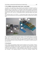
3.3.2 Experimental results
The static and dynamic performances of the proposed closed-loop pressure control system
have been analyzed by using the test-bed of Fig.15. Some experimental results in the time
domain are reported in Fig.17 in order to show the effects of the proportional gain Kp of the
PID compensator. In particular, the reference and output pressure signals P
SET
and P
OUT
are
compared by increasing the values of the proportional gain Kp from 0.3 to 2.4, as shown in
Figs.17a to 17d, respectively. Taking into account that the pressure transducer Tp is
characterized by a static gain K
T
= 1 V/bar, the pressure diagrams of P
SET
and P
OUT
show the
same shape and values of the correspondent voltage diagrams V
SET
and V
F/B
, respectively.
Moreover, the diagram of Fig.17c shows a good behaviour at high values of Kp, even if some
instability of the system may appear, as shown in Fig.17d for Kp = 2.4. The experimental
closed-loop frequency response of the proposed pressure control system has been carried out
by using a Gain-Phase-Analyzer of type SI 1253. The Bode diagrams of Fig.18a and 18b have
been obtained for the periods of the PWM modulation, T = 50 ms and T = 100 ms, respectively.
Thus, the diagrams of the pressure signals P
SET
and P
OUT
versus time, which have been
acquired through the Lab-View Data-Acquisition-System, are shown in continuous and
dash-dot lines, respectively. In particular, Figs.19a and 19b show both frequency responses
of Fig.18a and 18b in the time domain for a P
SET
sinusoidal pressure signal with frequency
f = 0.1 Hz, average value Av = 3 bar rel and amplitude A = 2 bar rel. Likewise to the
diagrams of Fig.20 and still referring to the Bode diagrams of Fig.18, the frequency
responses in the time domain for a P
SET
with frequency f = 1.5 Hz are shown respectively in
Fig.20a and 20b for T = 50 ms and T = 100 ms.
4 6 8 10 12 14
0
1
2
3
4
5
6
time[s]
P
SET
, P
OUT
[bar rel]
4 6 8 10 12 14
0
1
2
3
4
5
6
time[s]
P
SET
, P
OUT
[bar rel]
a) b)
4 6 8 10 12
0
1
2
3
4
5
6
time[s]
P
SET
, P
OUT
[bar rel]
4 6 8 10 12
0
1
2
3
4
5
6
time[s]
P
SET
, P
OUT
[bar rel]
c) d)
Fig. 17. Effects of the proportional gain: a) Kp = 0.3; b) Kp = 0.9; c) Kp = 1.8; d) Kp = 2.4.
Advances in Mechatronics
148
10
-1
10
0
-6
-4
-2
0
2
amplitude [dB]
10
-1
10
0
-100
-50
0
phase [deg]
frequency [Hz]
10
-1
10
0
-6
-4
-2
0
2
amplitude [dB]
10
-1
10
0
-100
-50
0
fre
q
uenc
y
[
Hz
]
phase [deg]
a) b)
Fig. 18. Closed-loop frequency responses of the proposed pressure control system for
different periods of the PWM modulation; a) T = 50 ms; b) T = 100 ms.
20 25 30 35
0
1
2
3
4
5
6
Pset, Pout [bar rel]
time [s]
10 15 20 25
0
1
2
3
4
5
6
Pset, Pout [bar rel]
time [s]
a) b)
Fig. 19. Frequency responses in the time domain for a sinusoidal P
SET
with f = 0.1 Hz,
Av = 3 bar rel and A = 2 bar rel: a) T = 50 ms; b) T = 100 ms.
5 6 7 8 9 10
0
1
2
3
4
5
6
Pset, Pout [bar rel]
time [s]
5 6 7 8 9 10
0
1
2
3
4
5
6
p
Pset, Pout [bar rel]
time [s]
a) b)
Fig. 20. Frequency responses in the time domain for a sinusoidal P
SET
with f = 1.5 Hz,
Av = 3 V and A = 2 V: a) T = 50 ms; b) T = 100 ms.