Advances in Mechatronics Part 10 pot
Bạn đang xem bản rút gọn của tài liệu. Xem và tải ngay bản đầy đủ của tài liệu tại đây (587.36 KB, 20 trang )
Robotic Grasping and Fine Manipulation Using Soft Fingertip
169
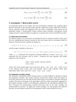
Fig. 9. Final adjusted vertical displacement of object vs time and corresponding rootlocus of
the dynamic system.
Advances in Mechatronics
170
5. Discussion
The objective of this work is to design and develop a robotic gripper which has soft fingers
like human fingers. Soft fingers have ability to provide area contact which helps in
dexterous grasping, stability and fine manipulation of the gripping object. This work is a
step towards this final goal. We have carried out a detailed parametric study of the dynamic
system and have observed the effects of changing material properties on the dynamics of the
soft contact grasping system. In this work my objective is to optimize the values of spring
stiffness and damping in the soft finger for an effective grasping. This has been achieved by
making many simulated experiments.
The poles of the system have negative real parts (-0.9017, -0.3050, -16.59+23.3j, -16.59-23.3j)
thus the exponential terms will eventually decay to zero. Since, for the springs and the
dampers which specify the viscoelastic property of the soft contact fingers, the poles have
negative real parts, the system is stable. Table 2 to 5 show the consolidated results found from the
simulated experiments shown in figures 7-9. The left side curves present the response of the
object vertical displacement with respect to time and the right side curves present the root
locus for the corresponding system poles. Initially the system was settling down slow as the
dominant poles are very close to the imaginary axis. Thus a zero is introduced to cancel the
effect of dominant pole as seen by comparing the figures 7 and 9, and the root locus is
pulled away from the imaginary axis to settle down the system quickly.
Sr #
=
[N/m]
=
[Ns/m]
=
[Ns/m]
Peak
value
[mm]
Peak
Time
[ms]
Steady State
Displacement
Value [mm]
Settling
Time
[s]
1 10 10 20 21.7 73.5 7.67 4.4
2 25 10 20 20.9 67.7 7.5 2.2
3 50 10 20 20.2 56.0 7.5 1.06
4 100 10 20 19.2 44.4 7.5 0.5
5 200 10 20 17.5 26.8 7.5 0.19
Table 2. Results of the simulated experiments by varying stiffness of springs and keeping
damping and friction constant.
Sr #
=
[N/m]
=
[Ns/m]
=
[Ns/m]
Peak
value
[mm]
Peak
Time
[ms]
Steady State
Displacement
Value [mm]
Settling
Time
[s]
1 200 15 20 15.3 33.5 7.5 0.276
2 200 20 20 13.7 31.5 7.5 0.412
3 200 25 20 12.7 29.2 7.5 0.519
4 200 30 20 11.9 24.2 7.5 0.604
Table 3. Results of the simulated experiments by varying damping and keeping stiffness of
springs and friction constant.
Robotic Grasping and Fine Manipulation Using Soft Fingertip
171
Sr #
=
[N/m]
=
[Ns/m]
=
[Ns/m]
Peak
value
[mm]
Peak
Time
[ms]
Steady State
Displacement
Value [mm]
Settling
Time
[s]
1 200 30 50 7.5 22.9 3.05 0.679
2 200 30 100 6.06 19.4 1.53 0.76
3 200 30 150 5.56 19.2 1.03 0.759
4 200 30 200 5.3 18.14 0.79 0.699
Table 4. Results of the simulated experiments by varying friction and keeping damping and
stiffness of springs constant.
Sr #
=
[N/m]
=
[Ns/m]
=
[Ns/m]
Peak
value
[mm]
Peak
Time
[ms]
Steady State
Displacement
Value [mm]
Settling
Time
[s]
1 200 10 200 11.36 31.8 0.74 0.224
2 250 10 200 10.9 28.8 0.64 0.176
3 250 10 250 10.8 25.2 0.47 0.155
4 250 10 300 10.4 25.2 0.17 0.154
Table 5. Optimum results of the simulated experiments.
6. Conclusion
A new approach to design an effective soft contact grasping system is presented in this
research work portion. The parametric study is made to evolve suitable values of material
properties for an effective grasping. The bond graph modeling technique has been applied
to obtain the precise mathematical model of the two soft contact robotic fingers. The two
fingers are made soft by introducing linear mass, spring, and damper effects in them. The
object is controlled by the friction between the fingers from slippage. It would have taken a
lot more effort to get these results using traditional methods.
From the simulated results presented in Table 2 to 5, it is concluded that the friction, when
increased between the contact surfaces, reduces the displacement of the object. Secondly the
damping of the soft fingers when increased controls the peak value of displacement of object
and also brings the stable value close to zero. Thirdly the stiffness of the spring effects the
settling time of the object. Therefore, the damping of soft finger and the stiffness of the
spring in the soft finger and the friction between the soft contact surfaces effects
considerably in manipulation of the object. Combination of the stiffness and the damping is
the viscoelastic property of the material. The flow signal is produced due to the applied
forces on the fingers by some separate mechanism which is not the part of this work but
may be designed or procured for experiments.
Advances in Mechatronics
172
7. Acknowledgement
The author is indebted to College of E & ME, National University of Sciences and
Technology, Rawalpindi, Pakistan for having made this research work possible.
8. References
[1] M. R. Cutkosky, “Robotic Grasping and Fine Manipulation,” Kluwer Academic
Publishers, 1985.
[2] M. Mason, and K. Salisbury, “Robot Hands and Mechanics of Manipulation,”MIT Press,
1986.
[3] R. Murray, Z. Li, and S. Sastry, “A mathematical introduction torobotic manipulation,”
CRC Press, 1999.
[4] T. Yoshikawa, and K. Nagai, “Manipulating and Grasping Forces in Multifingered Robot
Hands,” IEEE Tras. on Robotics and Automation, Vol.7-1, pp. 67-77, 1991.
[5] A. Namiki, and M. Ishikawa, “Optimal grasping using visual and tactile feedback,” Proc.
of IEEE Int. Conf. on Multisensor Fusion and Intelligent Systems, pp. 584-596,
1996.
[6] Y. Maeda, and T. Arai, “A Quantitative Stability Measure for Graspless Manipulation,”
Proc. of IEEE Int. Conf. on Robotics and Automation, pp. 2473-2478, 2002.
[7] A. Bicchi, “Force Distribution in Multiple Whole-Limb Manipulation,” Proc. of IEEE Int.
Conf. on Robotics and Automation, pp. 196-201, 1993.
[8] S. Arimoto, P. T. A. Nguyen, H. Y. Han, and Z. Doulgeri, “Dynamics and control of a set
of dual fingers with soft tips,” Robotica, Vol.18, No.1, pp. 71-80, 2000.
[9] S. Arimoto, Z. Doulgeri, P. T. A. Nguyen, and J. Fasoulas, “Stable pinching by pair of
robot fingers with soft tips under the effect of gravity,” Robotica, Vol.20, No.1, pp.
1-11, 2002.
[10] S. D. Eppinger, and W. P. Seering, “Three Dynamics Problems in Robot Force Control,”
Proc. of IEEE Int. Conf. on Robotics and Automation, pp. 392-397, 1989.
[11] K. B. Shimoga, and A. A. Goldenberg, “Soft Robotic Fingers: Part I. A Comparison of
Construction Materials,” International Journal of Robotics Research, pp. 320-334,
1996.
[12] K. B. Shimoga, and A. A. Goldenberg, “Soft Robotic Fingers: Part II. Modeling and
Impedance Regulation,” International Journal of Robotics Research, pp. 335-350,
1996.
[13] E.N.Ohwovoriole “Kinematics and Friction in Grasping by Robotic Hands” 398/ Vol. 109,
Sep 1987, ASME Transactions.
[14] Lakshminarayana, K., “Mechanics of Form Closure”, 1978, ASME 78-DET-32.
[15] Trinkle, J.C, Abel, J.M. and Paul, R. P., 1988, “An Investigation of Enveloping Grasping in the
Plane”, International Journal of Robotics Research, vol. 3 no. pp. 33-55.
[16] Trinkle, J.C., ‘On the Stability and Instantaneous Velocity of Grasped Frictionless Objects’,
IEEE J. Robotics and Automation, vol. 8, no. 5, 1992, pp. 560-572.
[17] Robot Grippers by Gareth J. Monkman, Stefan hesse, Ralf Strinmann, Henrick Schunk.
Edited, designed and published by Wiley-vch, pp 2.
Robotic Grasping and Fine Manipulation Using Soft Fingertip
173
[18] Robot Grippers by Gareth J. Monkman, Stefan hesse, Ralf Strinmann, Henrick Schunk.
Edited, designed and published by Wiley-vch, pp 24.
[19] Robot Grippers by Gareth J. Monkman, Stefan hesse, Ralf Strinmann, Henrick Schunk.
Edited, designed and published by Wiley-vch, pp 19.
[20] Mechanical engineering handbook By Lewis F.L. CRC Press LLC, 1999; page
14-24
[21] Journal of the Brazilian Society of Mechanical Sciences and Engineering version ISSN
1678-587 J. Braz. Soc. Mech. Sci. & Eng. vol.31 no.4
[22] J.S. Son, E.A. Monteverde, and R.D. Howe, “A Tactile Sensor for Localizing Transient
Events in extrapolated from our findings for the two-dimensional problem. We
note that for the case of fingertips with two Manipulation,” Proceedings of the 1994
IEEE International. Conference on Robotics and Automation pp. 471-476, San Diego,
May 1994.
[23] M. Tremblay and M.R. Cutkosky, “Estimating friction using incipient slip sensing
during a manipulation will cause contact trajectories to deviate from the
expected paths. This effect is illustrated in Figure 4, for the case of task,”
Proceedings of the 1993 IEEE International Conference on Robotics and Automation
, pp. 429-434, Atlanta, Georgia, May 1993.
[24] R.D. Howe and M.R. Cutkosky, “Sensing skin acceleration for texture and slip
perception,” rigid or undeformed fingertip and for the case of a deformed
fingertip for which rolling velocities are Proceedings of the 1989 IEEE International
Conference on Robotics and Automation, pp. 145-150, Scottsdale, Arizona, May
1989.
[25] R.A. Russell, S. Parkinson, “Sensing Surface Shape by Touch,” that the deformed
fingertip follows a trajectory that diverges from the trajectory predicted
by rigid body Proceedings of the 1993 IEEE International Conference on Robotics
and Automation , pp. 423-428, Atlanta, Georgia, May 1993.
[26] K.B. Shimoga and A.A. Goldenberg, “Soft Materials for Robotic Fingers,”
Proceedings of the 1992 IEEE International Conference on Robotics and Automation pp.
1300-1305, Nice, France, May 1992.
[27] A Khurshid and M A Malik, “Modeling and Simulation of an automotive system by using
Bond Graphs” 10
th
International Symposium on Advanced Materials ISAM 2007
Islamabad, Pakistan.
[28] A Khurshid and M A Malik, “Bond Graph Modeling and Simulation of Impact
Dynamics of a Car Crash” 5
th
International Bhurban Conference On Applied
Sciences And Technology 5
th
IBCAST-2007, Islamabad, Pakistan.
[29] A Khurshid and M A Malik, “Modeling and Simulation of a Quarter Car Suspension
System using Bond Graphs” 9
th
International Symposium on Advanced Materials
ISAM 2005, Islamabad, Pakistan.
[30] A Khurshid and M A Malik, “Bond Graph Modeling and Simulation of Mechatronic
Systems” International Multi-topic Conference 2003, INMIC 2003, In association
with IEEE, Islamabad, Pakistan.
[31] A. Mukherjee, R. Karmakar, Modeling and simulation of engineering systems through
bond graphs, Narosa Publishing House, New Delhi, 2000.
Advances in Mechatronics
174
[32] D. C. Karnopp, D. L. Margolis, and R. C. Rosenberg, System Dynamics: Modeling and
simulation of mechatronic systems, third edition, Wiley-Interscience, 2000.
[33] 20-sim Control Laboratory, University of Twente Controllab Products B.V. Drienerlolaan 5
EL-CE, 7522 NB Enschede the Netherlands. 2003.
8
Recognition of Finger Motions for Myoelectric
Prosthetic Hand via Surface EMG
Chiharu Ishii
Hosei University
Japan
1. Introduction
Recently, myoelectric prosthetic arms/hands, in which arm/hand gesture is distinguished
by the identification of the surface electromyogram (SEMG) and the artificial arms/hands
are controlled based on the result of the identification, have been studied (Weir, 2003). The
SEMG has attracted an attention of researchers as an interface signal of an electric actuated
arm for many years, and many of studies on the identification of the SEMG signal have been
executed. Nowadays, it can be said that the SEMG is the most powerful source of control
signal to develop the myoelectric prosthetic arms/hands.
From the 1970s to the 1980s, elementary pattern recognition technique such as linear
discriminant analysis, was used for the identification of the SEMG signals in (Graupe et al.,
1978) and (Lee et al., 1984). In the 1990s, research on learning of a nonlinear map between
the SEMG pattern and arm/hand gesture using a neural network has been performed in
(Hudgins et al., 1993). Four kinds of motions of the forearm were distinguished by
combining Hopfield-type neural network and back propagation neural network in (Kelly et
al., 1990).
The amplitude and the frequency band are typical information extracted from the SEMG
signal, which can be used for the identification of arm/hand gesture. (Ito et al., 1992)
presumed muscle tension from the EMG signal, and tried to control the forearm type
myoelectric prosthetic arm driven by ultrasonic motor. (Farry et al., 1996) has proposed a
technique of teleoperating the robot hand through the identification of frequency spectrum
pattern of the SEMG signal.
At present, however, most of the myoelectric prosthetic arms/hands can only realize some
limited motions such as palmar seizure, flexion-extension of a wrist, and inward-outward
rotation of a wrist. To the best of our knowledge, myoelectric prosthetic hands which can
distinguish motions of plural fingers and can independently actuate each finger have not
been developed yet, since recognition of independent motions of plural fingers through the
SEMG is fairly difficult.
Probably, a present cutting edge practical myoelectric prosthetic hand is the "i-LIMB Hand"
produced by Touch Bionics Inc However, myoelectric prosthetic hands which imitate the
hand of human, such as the "i-LIMB Hand", are quite expensive, since they require accurate
measurement of SEMG signal and use many actuators to drive finger joints. Therefore,
improvement of operativity of the myoelectric prosthetic arms/hands and simplification of
structure of the artificial arms/hands to lower the price are in demand.
Advances in Mechatronics
176
The purpose of this study is to develop a myoelectric prosthetic hand which can
independently actuate each finger and can realize fundamental motions, such as holding
and grasping, required in daily life. In order to make it budget price, an underactuated
robotic hand structure which realizes flexion and extension of fingers by tendon mechanism,
is introduced. In addition, the "fit grasp mechanism" in which the fingers can fit the shape of
the object when the fingers grasp the object, is proposed. The "fit grasp mechanism" makes it
possible for the robotic hand to grasp a small object, a cylindrical object, a distorted object,
etc In this study, a robotic hand with the thumb and the index finger was designed and
built as a prototype.
As for the identification of independent motion of each finger, using the neural network, an
identifier which distinguishes four finger motions, namely flexion and extension of the
thumb and the index finger in respective metacarpophalangeal (MP) joint, is constructed.
Four patterns of neural network based identifiers are proposed and the recognition rates of
each identifier are compared through simulations and experiments. The online control
experiment of the built robot hand was conducted using the identifier which showed the
best recognition rate.
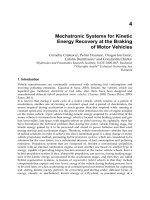
2. Robot hand
In this section, details of the robot hand for myoelectric prosthetic hand are explained.
Overview of the built underactuated robot hand with two fingers, namely the thumb and
the index finger, is shown in Fig.1.
Fig. 1. Overview of robot hand.
2.1 Specifications
The primary specifications of the robot hand are shown as follows.
1. Entire hand: 500mm total length, and 50mm thickness
2. Palm: 100mm length, 110mm width, and 20mm thickness
3. Finger: 100mm length, 15mm width, and 10mm thickness
4. Pinching force when MP joint is driven: 3N
Recognition of Finger Motions for Myoelectric Prosthetic Hand via Surface EMG
177
2.2 Mechanism of finger
As shown in Fig.2, imitating the human's frame structure, the robot hand has finger
mechanism which consists of three joints, namely distal interphalangeal joint (DIP: the first
joint), proximal interphalangeal joint (PIP: the second joint), and metacarpophalangeal joint
(MP: the third joint). The fingers are driven by the wire actuation system like human's
tendon mechanism. When the wire connected with each joint is pulled by driving force of
the actuator, the finger bends. While, when the tension of the wire is loosed, the finger
extends due to the elastic force of the rubber. This makes it possible to omit actuators used
to extend the finger. The built robot hand can realize fundamental operation required in
daily life, such as holding and grasping.
DIP
PIP
MP
Rubber
DIP
PIP
MP
Rubber
Fig. 2. Mechanism of finger.
2.3 Fit grasp mechanism
In general, when human holds the object, the fingers flexibly fit the shape of the object so
that the object can be wrapped in. We call this motion "fit grasp motion". As shown in Fig.3,
the finger of the robot hand has two kinds of wires which perform interlocked motion in
DIP and PIP joints and motion in MP joint respectively. Therefore, the interlocked bending
in DIP and PIP joints and the bending in MP joint can be performed independently.
DIP
PIP
MP
Rubber
DIP
PIP
MP
Rubber
Fig. 3. Arrangement of wires.
In addition, as shown in Fig.3, the ring is attached to the wire between DIP joint and PIP
joint, and the interlocked motion of DIP and PIP joints is achieved by pulling the ring by
other wire connected to the ring. This mechanism allows to realize "fit grasp motion". We
Advances in Mechatronics
178
call this mechanism "fit grasp mechanism." Details of the "fit grasp motion" are illustrated in
Fig.4.
Fig. 4. Bending motion by fit grasp mechanism.
In the case where there is no object to hold, when the wire is pulled by the actuator, DIP and
PIP joints bend at the almost same angle (Fig.4 upper). On the other hand, in the case where
there is object to hold, when the object contacts the finger, only one side of the wire is pulled
since the wire between DIP joint and PIP joint can slide inside of the ring. As a result, DIP
joint can bend in accordance with the shape of the object (Fig.4 lower). Thus, "fit grasp
motion" is achieved. The "fit grasp mechanism" makes it possible for the robotic hand to
grasp a small object, a cylindrical object, a distorted object, etc
3. Measurement and signal processing of SEMG
In this section, measurement and signal processing of the SEMG are described.
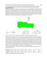
3.1 Measurement positions of SEMG
The built robot hand for myoelectric prosthetic hand has thumb and index finger to operate,
and the thumb and the index finger are operated independently. Various motions of each
finger can be considered, however in this study, flexion and extension of the thumb and the
index finger in MP joint are focused on. Namely, flexion and extension in interlocked DIP
and PIP joints are not considered here. Inward rotation and outward rotation of each finger
are also not taken into consideration.
The measurement positions of SEMG are shown in Fig.5. Those are the following three
positions; the vicinity of a musculus flexor carpi radialis / a musculus flexor digitorum
superficialis (ch1), the vicinity of a musculus flexor digitorum profundus (ch2), and the
vicinity of a musculus extensor digitorum (ch3). The former two musculuses are used for
flexion of each finger and the latter musculus is used for extension of each finger.
Recognition of Finger Motions for Myoelectric Prosthetic Hand via Surface EMG
179
Fig. 5. Measurement positions of SEMG
3.2 Signal processing
One finger motion is performed in approximately 0.5 second, and the SEMG signal is
measured by 1kHz of sampling frequencies. Fast Fourier Transform (FFT) is performed to
the measured SEMG signals, and spectral analysis is conducted. The number of samples for
FFT was set as 256. When performing FFT, the humming window function was utilized to
the processing signals.
However, influence of the alternate current (AC) power source, which is regarded as an
external noise, appears in the amplitude value of the SEMG by which FFT processing was
carried out. This AC power source noise appears at odd times frequencies of the
fundamental frequency. Since the area where this experiment was conducted is East Japan,
as shown in Fig.6, the influence of the AC power source noise appears at 50Hz and 150Hz.
Frequency
Amplitude
Frequency
Amplitude
Fig. 6. Spectrum of SEMG signal
Since it is considered that least influence of the AC power source noise is at 100Hz, the
amplitude value at 100Hz is used for recognition of the finger motions.
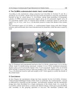
Three-dimensional graph of the amplitude values at 100Hz of each motion in MP joint is
shown in Fig.7, in which each measurement position, namely each electrode, is taken as an
axis of the coordinates. In addition, the distribution in Fig.7 was divided into the
distribution along the thumb and the index finger respectively, which are shown in Fig.8
and Fig.9.
Advances in Mechatronics
180
Fig. 7. Distribution of amplitude values at 100 Hz.
Fig. 8. Distribution of amplitude values at 100 Hz (thumb).
Recognition of Finger Motions for Myoelectric Prosthetic Hand via Surface EMG
181
Fig. 9. Distribution of amplitude values at 100 Hz (index finger).
The amplitude values of flexion of the index finger are distributed over the whole space.
Hence, it is anticipated that it is hard to distinguish the flexion of the index finger from
extension of the index finger. However, in the case of the thumb, the distribution seems to
be distinguishable to flexion or extension. Therefore, these values are used for recognition of
the finger motions.
4. Recognition of finger motions
In this section, the identification methods of finger motions using neural network(s) are
explained.
4.1 Recognition by one neural network
The recognition of the finger motions is performed via SEMG signals using neural
network(s). First of all, an identifier which distinguishes four finger motions, namely 1) the
flexion of the thumb in MP joint, 2) the extension of the thumb in MP joint, 3) the flexion of
the index finger in MP joint, and 4) the extension of the index finger in MP joint, by only one
neural network is constructed.
The input signals to the neural network are set of the amplitude values at 100Hz obtained
through the signal processing explained in Section 3.2 for the SEMG signal measured in each
electrode. The numerical values 1 to 4, 1 for flexion of the thumb, 2 for extension of the
thumb, 3 for flexion of the index finger and 4 for extension of the index finger, are assigned
as the teacher signals for each motion.
As for the structure of the neural network, the feedforward neural network was adopted.
The number of the input layer and of the output layer is one, respectively, and the number
of the hidden layer, each consisting of three neurons, is two. 20 set of pre-measured input
Advances in Mechatronics
182
signals for each finger motion were used for learning of the neural network. The error back
propagation algorithm was used as the learning method of the neural network. The learning
of the feedforward neural network was executed using the Neural Network Toolbox in
MATLAB software. As a condition of the learning, the end of the learning was set with the
repetition of 10000 times calculation. Hereafter, this identification method, namely
recognition of the four finger motions by one neural network, is described as identifier (x).
After the learning of the neural network, simulation was carried out using the 30 set of pre-
measured input signals for each finger motion, which differs from the input signals used for
the learning, and its recognition rate was examined. The results are shown in Table 1.
Motion
Flexion of
thumb
Extension of
thumb
Flexion of
index finger
Extension of
index finger
Average
Recognition rate [%] 43.3 0.0 36.6 3.3 20.8
Table 1. Simulation results with identifier (x).
From Table 1, the successful recognition rate was only 20.8% on average for use of the
identifier (x).
4.2 Improvement of identification method
The improvement of the recognition rate can be expected by modifying the identification
method. By reducing the number of choice which one neural network should distinguish,
and combining two or more neural networks in series or in parallel, much higher successful
recognition rate will be obtained for each finger motion. In each neural network, the choice
is given as alternative, namely the numerical values 0 and 1 are given as the teacher signals.
The following three patterns of identifier shown in Fig.10 are considered.
Recognition of
flexion of index finger
(N.N 1)
Flexion of thumb
(a)
Extension of thumb Extension of index finger
Recognition of
extension of index finger
(N.N 3)
0 No
1 Yes 1 Yes 1 Yes
Recognition of
extension of thumb
(N.N 2)
Flexion of index finger
0 No 0 No
Recognition of
flexion of index finger
(N.N 1)
Flexion of thumb
(a)
Extension of thumb Extension of index finger
Recognition of
extension of index finger
(N.N 3)
0 No0 No
1 Yes1 Yes 1 Yes1 Yes 1 Yes1 Yes
Recognition of
extension of thumb
(N.N 2)
Flexion of index finger
0 No0 No 0 No0 No
Flexion of index finger
(b)
Recognition of
thumb or index finger
in flexion (N.N 2)
Recognition of
flexion or extension
(N.N 1)
Recognition of
thumb or index finger
in extension (N.N 3)
0 Extension
1 Flexion
1 Thumb
Flexion of thumb
Extension of thumb
Extension of index finger
1 Thumb
0 Index finger
0 Index finger
Flexion of index finger
(b)
Recognition of
thumb or index finger
in flexion (N.N 2)
Recognition of
flexion or extension
(N.N 1)
Recognition of
thumb or index finger
in extension (N.N 3)
0 Extension
0 Extension
1 Flexion1 Flexion
1 Thumb1 Thumb
Flexion of thumb
Extension of thumb
Extension of index finger
1 Thumb
1 Thumb
0 Index finger0 Index finger
0 Index finger0 Index finger
(c)
Recognition of
thumb or index finger
(N.N 1)
Flexion of index finger
Recognition of
flexion or extension
in thumb (N.N 2)
Recognition of
flexion or extension
in index finger (N.N 3)
1 Index finger
Flexion of thumb
Extension of thumb
Extension of index finger
0 Thumb
1 Flexion
1 Flexion
0 Extension
0 Extension
(c)
Recognition of
thumb or index finger
(N.N 1)
Flexion of index finger
Recognition of
flexion or extension
in thumb (N.N 2)
Recognition of
flexion or extension
in index finger (N.N 3)
1 Index finger
1 Index finger
Flexion of thumb
Extension of thumb
Extension of index finger
0 Thumb
0 Thumb
1 Flexion1 Flexion
1 Flexion1 Flexion
0 Extension0 Extension
0 Extension0 Extension
Fig. 10. Improved identification methods.
Recognition of Finger Motions for Myoelectric Prosthetic Hand via Surface EMG
183
In identifier (a), the finger motion is distinguished by recognizing each one motion by one
neural network in order with high successful recognition rate for each finger motion. The
order of recognition by neural network was determined through simulation results, as
flexion of the index finger, extension of the thumb and extension of the index finger. First,
N.N 1 identifies whether the finger motion is flexion of the index finger. N.N 1 is trained to
output 1 for flexion of the index finger and 0 for other finger motions by the learning.
Therefore, N.N 1 outputs 1 in the case where the finger motion is identified as flexion of the
index finger. If the output of N.N 1 is 0, likewise N.N 2 identifies whether the finger
motion is extension of the thumb. Again, if the output of N.N 2 is 0, N.N 3 identifies
whether the finger motion is extension of the index finger. Finally, in the case where the
finger motion was not identified as any of these three motions, it is finally recognized as
flexion of the thumb. This identification method has drawback that incorrectly-identified
finger motions are inevitably distinguished as flexion of the thumb.
In identifier (b), N.N 1 is trained to output 1 for flexion of the thumb and the index finger
and 0 for extension of the thumb and the index finger, and N.N 2 and N.N 3 are trained to
output 1 for motion of the thumb and 0 for motion of the index finger. Firstly the flexion or
the extension is distinguished, then motion of the thumb or motion of the index finger is
distinguished. Thus, finally motion of the finger is distinguished to one of the finger
motions.
In identifier (c), N.N 1 is trained to output 1 for motion of the thumb and 0 for motion of the
index finger, and N.N 2 and N.N 3 are trained to output 1 for the flexion and 0 for the
extension. Firstly, motion of the thumb or motion of the index finger is distinguished, then
the flexion or the extension is distinguished. Thus, finally motion of the finger is
distinguished to one of the finger motions.
In identifier (b) and identifier (c), the first distinction is important, since if the first
distinction is incorrect, subsequent distinction becomes meaningless. Therefore, high
successful recognition rate of the first distinction is required.
The structure of each neural network and the learning method are same as the identifier (x).
Namely, in each identifier, the error back propagation algorithm was used as the learning
method for respective feedforward neural network.
4.3 Simulation with improved identification method
Simulation works for distinction of the finger motions were carried out for each identifier,
and each recognition rate was examined. In each identifier, simulation was carried out using
the 30 set of pre-measured input signals for each finger motion, which differs from the input
signals used for the learning. The result using the identifier (a) is shown in Table 2.
Motion
Flexion of
thumb
Extension of
thumb
Flexion of
index finger
Extension of
index finger
Average
Recognition
rate [%]
66.7 30.0 90.0 43.3 57.5
Table 2. Simulation results with identifier (a).
Table 2 shows that the recognition rate was improved compared with the identifier (x).
However, since most of the incorrectly-identified motions are distinguished as flexion of the
thumb, improvement is required.
Advances in Mechatronics
184
Before simulating entire recognition rate using identifier (b), recognition rate of each neural
network in identifier (b) was examined. In the simulation, the 30 set of input signals for each
finger motion were used in N.N 1. Each 30 set of input signals for flexion of the thumb and
flexion of the index finger were used in N.N 2, and each 30 set of input signals for extension
of the thumb and extension of the index finger were used in N.N 3. The results are shown
in Table 3.
N.N 1 Flexion Extension Average
Recognition rate [%] 83.3 76.7 80.0
N.N 2 Flexion of thumb
Flexion of index
finger
Average
Recognition rate [%] 93.3 86.7 90.0
N.N 3
Extension of
thumb
Extension of index
finger
Average
Recognition rate [%] 53.3 73.3 63.3
Table 3. Partial recognition rate for each neural network in identifier (b).
From Table 3, the recognition rate of 80% on average was obtained at the first distinction.
The result of entire recognition rate using identifier (b) is shown in Table 4.
Motion
Flexion of
thumb
Extension of
thumb
Flexion of
index finger
Extension of
index finger
Average
Recognition
rate [%]
66.7 33.3 83.3 63.3 61.65
Table 4. Simulation results with identifier (b).
Table 4 shows that the entire recognition rate was improved as well as identifier (a).
Likewise, before simulating entire recognition rate using identifier (c), recognition rate of
each neural network in identifier (c) was examined. In the simulation, the 30 set of input
signals for each finger motion were used in N.N 1. Each 30 set of input signals for flexion of
the thumb and extension of the thumb were used in N.N 2, and each 30 set of input signals
for flexion of the index finger and extension of the index finger were used in N.N 3. The
results are shown in Table 5.
N.N 1 Thumb Index finger Average
Recognition rate [%] 80.0 55.0 67.5
N.N 2 Flexion of thumb
Extension of
thumb
Average
Recognition rate [%] 80.0 100 90.0
N.N 3
Flexion of index
finger
Extension of index
finger
Average
Recognition rate [%] 83.3 90.0 86.7
Table 5. Partial recognition rate for each neural network in identifier (c).
From Table 5, the recognition rate of the first distinction was only 67.5% on average, which
is inferior to the case of the identifier (b). The result of entire recognition rate using identifier
(c) is shown in Table 6.
Recognition of Finger Motions for Myoelectric Prosthetic Hand via Surface EMG
185
Motion
Flexion of
thumb
Extension of
thumb
Flexion of
index finger
Extension of
index finger
Average
Recognition
rate [%]
70.0 70.0 76.7 13.3 57.5
Table 6. Simulation results with identifier (c).
From Table 6, the entire recognition rate of 57.5% on average was obtained, which is almost
same level as the identifier (a).
From the above results, it turned out that the recognition rate was improved in all identifiers
(a), (b) and (c), compared with identifier (x). In addition, from the recognition rate of N.N 1
in Table 3 and of N.N 2 and N.N 3 in Table 5, it can be said that distinction between the
flexion and the extension is comparatively easy as compared with distinction between the
thumb and the index finger.
5. Experiments
In this section, experimental results for online recognition and for online finger operation of
the robot hand described in Section 2 are shown.
5.1 Experiment for online recognition
Experiment for online recognition of the finger motions was carried out using the identifier
(b) which showed the most successful recognition rate on average, and recognition rate was
examined. Each finger motion was performed in 1 second at intervals of about 10 seconds.
The result of the recognition rate for 60 times of movements for each finger motion is shown
in Table 7.
Motion
Flexion of
thumb
Extension of
thumb
Flexion of
index finger
Extension of
index finger
Average
Recognition
Rate [%]
68.3 33.3 81.8 60.0 60.8
Table 7. Experimental results for online recognition with identifier (b).
Compared with the simulation results shown in Table 4, quite similar results were obtained.
5.2 Experiment for online control of robot hand
Experiment for online finger operation of the robot hand was executed. In the experiment,
the SEMG of each electrode is measured online. Then, the start time of finger motion is
detected as follows. Since the SEMG of ch1 has least noise and good response among the
SEMG of ch1, ch2 and ch3, the SEMG of ch1 is rectified, and when the magnitude of the
rectified SEMG exceeds a specified threshold, it is regarded as finger motion having begun.
Synchronizing with the start of the finger motion, online recognition of the finger motion
using the identifier (b) is carried out. In the experiment, the finger motion is performed in 1
second at intervals of about 5 seconds, respectively, and is performed in order with flexion
of the thumb, extension of the thumb, flexion of the index finger, and extension of the index
finger. The fingers of the robot hand are controlled based on the recognition result of the
identifier.
The measured SEMG in each electrode when a series of finger motion was performed is
shown in Fig.11.
Advances in Mechatronics
186
0 5 10 15 20 25
-2
0
2
SEMG (ch1)
Time[sec]
Voltage[mV]
0 5 10 15 20 25
-2
0
2
SEMG (ch2)
Time[sec]
Voltage[mV]
0 5 10 15 20 25
-2
0
2
SEMG (ch3)
Time[sec]
Voltage[mV]
Fig. 11. SEMG in each electrode.
0 5 10 15 20 25
4
6
8
10
12
Rectified SEMG (ch1)
Time[sec]
Voltage[mV]
0 5 10 15 20 25
-0.5
0
0.5
1
1.5
Transition of finger motion
Time[sec]
1: Flexion
0: Extension
0 5 10 15 20 25
4
6
8
10
12
Rectified SEMG (ch1)
Time[sec]
Voltage[mV]
0 5 10 15 20 25
-0.5
0
0.5
1
1.5
Transition of finger motion
Time[sec]
0 5 10 15 20 25
4
6
8
10
12
Rectified SEMG (ch1)
Time[sec]
Voltage[mV]
0 5 10 15 20 25
-0.5
0
0.5
1
1.5
Transition of finger motion
Time[sec]
1: Flexion
0: Extension
Fig. 12. Judgment of start of finger motion
Recognition of Finger Motions for Myoelectric Prosthetic Hand via Surface EMG
187
The SEMG of ch1 in Fig.11 was rectified, and the time when the magnitude of the rectified
SEMG exceeded the threshold determined as 9mV, was regarded as the start time of the
finger motion. The rectified SEMG of ch1 is shown at the top of Fig.12, and the transition of
the finger motion based on the judgment of the start of the finger motion is shown at the
bottom of Fig.12, in which "output 1" shows the flexion and "output 0" shows the extension.
Synchronizing with the start time of the finger motion shown in Fig.12, the input signal to
the neural networks in the identifier is updated. The recognition result of each neural
network in the identifier is shown in Fig.13.
N.N 1 distinguishes the flexion or the extension. The output larger than 0.5, which is
regarded as 1, is judged to be the flexion, and the output less than 0.5, which is regarded as
0, is judged to be the extension. N.N 2 and N.N 3 distinguish motion of the thumb or
motion of the index finger. The output larger than 0.5, which is regarded as 1, is judged to
be motion of the thumb, and the output less than 0.5, which is regarded as 0, is judged to be
motion of the index finger.
In Fig.13, the blue dashed line shows the output from the neural network, and the red solid
line shows the recognition result, in which "Output 1" shows the flexion and "Output 0"
shows the extension for N.N 1, and "Output 1" shows the motion of the thumb and "Output
0" shows the motion of the index finger for N.N 2 and N.N 3.
0 5 10 15 20 25
-0.5
0
0.5
1
1.5
N.N 1
Time[sec]
Output
0 5 10 15 20 25
-0.5
0
0.5
1
1.5
N.N 2
Time[sec]
Output
0 5 10 15 20 25
-0.5
0
0.5
1
1.5
N.N 3
Time[sec]
Output
Fig. 13. Recognition result for each neural network.
When Fig.12 and Fig.13 are compared, a slight time delay is seen until the recognition result
is obtained by the neural network after the start of the finger motion was judged, since it
takes a slight time to calculate the input signal to the neural network due to the FFT
processing and so on.
1: Flexion
0: Extension
0: Index finger
1: Thumb
1: Thumb
0: Index finger
Advances in Mechatronics
188
The entire recognition result of finger motion obtained from combination of the recognition
results of the three neural networks in Fig.13 is shown in Fig.14, in which "Output 4" shows
the flexion of the thumb, "Output 3" shows the extension of the thumb, "Output 2" shows the
flexion of the index finger, and "Output 1" shows the extension of the index finger. Initial
motion for 0 second to 5 seconds which has not operated any motion is judged as extension
of the thumb due to the learning of the neural network.
0 5 10 15 20 25
1
2
3
4
Results of recognition
Time[sec]
Output
Fig. 14. Recognition result of finger motion.
0 5 10 15 20 25
0
0.2
0.4
0.6
0.8
1
Robot hand operation (Thumb)
Time[sec]
Angle[rad]
0 5 10 15 20 25
0
0.5
1
1.5
2
2.5
3
Robot hand operation (Index finger)
Time[sec]
Angle[rad]
Fig. 15. Finger operation of robot hand.
1: Extension of index finger
2: Flexion of index finger
3: Extension of thumb
4: Flexion of thumb
- - : Reference value
: Actual rotation angle
- - : Reference value
: Actual rotation angle