Electric Vehicles Modelling and Simulations Part 9 docx
Bạn đang xem bản rút gọn của tài liệu. Xem và tải ngay bản đầy đủ của tài liệu tại đây (972.86 KB, 30 trang )
Hybrid Switched Reluctance Motor and Drives Applied on a Hybrid Electric Car
229
7.2 Results
Fig.11, Fig.12 and Fig.13 are the measured wave form of armature EMF (upper one) and
axial coil EMF when rotor speeds are 300 rpm, 1200rpm and 2400rpm. It is seen that there
are 6 zero points in the axial coil EMF signal corresponding in 1 cycle of armature EMF
signal which can be the commuted signals to drive motor.
(B: Axial coil EMF, A: Armature EMF)
Fig. 11. Measured wave form of axial coil emf and armature emf when 300rpm
(B: Axial coil EMF, A: Armature EMF)
Fig. 12. Measured wave form of axial coil emf and armature emf when 1200rpm
Electric Vehicles – Modelling and Simulations
230
(B: Axial coil EMF, A: Armature EMF)
Fig. 13. Measured wave form of armature EMF and axial coil EMF when 2400rpm
Fig.14 is torque-speed characteristic and efficiency map of the motor drives. Large torque
and high speed are obtained by flux adjusting control.
Fig. 14. Efficiency map of the motor drives
Hybrid Switched Reluctance Motor and Drives Applied on a Hybrid Electric Car
231
8. Conclusion
Demands of motor drive for a Mid-size hybrid electric car are analyzed by simulation. A
novel hybrid switched reluctance motor drive is developed which is suitable for applying in
electric vehicles. Frequency of EMF in axial coil is three times of that of terminal voltage
over one phase of radial coil, and is three times of that of EMF in radial coil. It means that
the axial coil can be the position sensor of rotor. Simple flux adjusting control is developed
to achieve large torque and high speed. An energy saving test bed is developed. With
applying the common DC bus technique, 4-quandrant electric machinery drive characteristic
testing is done simply without regenerative power to power grid.
9. Acknowledgment
This research is supported by Natural Scientific Research Innovation in Harbin Institute of
Technology (HIT. NSRIF. 2009042) and Scientific Research Foundation for Returned
Scholars by Harbin Science and Technology Bureau (RC2009LX007004).
10. References
[1] Z. Q. Zhu, David Howe. Electrical Machines and Drives for Electric, Hybrid, and Fuel
Cell Vehicles. Proceedings of the IEEE, 2007, 95(4):746-765.
[2] Avoki M. Omekanda. A New Technique for Multidimensional Performance
Optimization of Switched Reluctance Motors for Vehicle Propulsion. IEEE
Transactions on Industry Applications. 2003, 39(3): 672-676
[3] Teven E. Schulz, Khwaja M. Rahman. High-Performance Digital PI Current Regulator for
EV Switched Reluctance Motor Drives. IEEE Transactions on Industryl
Applications. 2003,39(4): 1118-
~1126
[4] Wei Cai, Pragasen Pillay, Zhangjun Tang. Low-Vibration Design of Switched Reluctance
Motors for Automotive Applications Using Modal Analysis. IEEE Transactions on
Industryl Applications. 2003, 39(4): 971
~977
[5] Cheng Shukang, Zheng Ping, Cui Shumei et al. Fundamental Research on Hybrid-
magnetic-circuit multi-couple Electric Machine, Proceedings of the CSEE, vol.20,
no. 4, pp.50-58, 2000.
[6] Zheng Ping, Cheng Shukang. Mechanism of Hybrid- Magnetic-circuit multi-couple
Motor. Journal of Harbin Institute of Technology, 2000, E-3(3), pp.66-69.
[7] Zheng Ping, Liu Yong, Wang Tiecheng et al. Theoretical and Experimental Research on
Hybrid-magnetic-circuit Multi-couple Motor. Seattle, USA: 39th IAS Annual
Meeting, 2004.
[8] Zhang Qianfan, Cheng Shukang, Song Liwei et al. Axial Excited Hybrid Reluctant Motor
Applied in Electric Vehicles and Research of its Axial Coil Signal. Magnetics, IEEE
Transactions, 2005, 41(1), pp.518-521.
[9] Pei Yulong, Zhang Qianfan, Cheng Shukang. Axial and Radial Air Gap Hybrid Magnet
Circuit Multi-coupling Motor and Resolution of Motor Electromagnetic Torque.
Power system technology, 2005, supplement.
[10] Zhang, Qian-Fan; Pei, Yu-Long; Cheng, Shu-Kang. Position sensor principle and axial
exciting coil EMF of axial and racial air gap hybrid magnet circuit multi-coupling
Electric Vehicles – Modelling and Simulations
232
motor. Proceedings of the Chinese Society of Electrical Engineering, v 25, n 22, Nov
16, 2005, p 136-141
[11] Zhang Qianfan, Chai Feng, Cheng Shukang, C.C. Chan. Hybrid Switched Reluctance
Integrated Starter and Generator. Vehicle Power and Propulsion Conference VPP
2006. September 6-8, 2006. Windsor, UK.
11
Mathematical Modelling and Simulation of a
PWM Inverter Controlled Brushless Motor Drive
System from Physical Principles for Electric
Vehicle Propulsion Applications
Richard A. Guinee
Cork Institute of Technology,
Ireland
1. Introduction
High performance electric motor drive systems are central to modern electric vehicle
propulsion systems (Emadi et al. , 2003) and are also widely used in industrial automation
(Dote, 1990) in such scenarios as numerical control (NC) machine tools and robotics. The
benefits accruing from the application of such drives are precision control of torque, speed
and position which promote superior electric vehicle dynamical performance (Miller, 2010)
with reduced greenhouse carbon gaseous emissions resulting in increased overall
automotive efficiencies. These electric motor drive attributes also contribute to enhanced
productivity in the industrial sector with high quality manufactured products. These
benefits arise from the fusion of modern adaptive control techniques (El Sarkawi, 1991) with
advances in motor technology, such as permanent magnet brushless motors, and high speed
solid-state switching converters which constitute the three essential ingredients of a high
performance embedded drive system. The controllers of these machine drives are
adaptively tuned to meet the essential requirements of system robustness and high tracking
performance without overstressing the hardware components (Demerdash et al, 1980;
Dawson et al, 1998). Conventional d.c. motors were traditionally used in adjustable speed
drive (ASD) applications because torque and flux control were easily achieved by the
respective adjustment of the armature and field currents in separately excited systems
where fast response was a requirement with high performance at very low speeds (Vas,
1998). These dc motors suffer from the drawback of a mechanical commutator assembly
fitted with brushes for electrical continuity of the rotor mounted armature coil which
increases the shaft inertia and reduces speed of response. Furthermore they require periodic
maintenance because of brush wear which limits motor life and the effectiveness of the
commutator for high speed applications due to arcing and heating with high current
carrying capacity (Murugesan, 1981).
Brushless motor drive (BLMD) systems, which incorporate wide bandwidth speed and
torque control loops, are extensively used in modern high performance EV and industrial
motive power applications as control kernels instead of conventional dc motors. Typical
high performance servodrive applications (Kuo, 1978; Electrocraft Corp, 1980) which require
high torque and precision control, include chemical processing, CNC machines, supervised
Electric Vehicles – Modelling and Simulations
234
actuation in aerospace and guided robotic manipulations (Asada et al, 1987). This is due
largely to the high torque-to-weight ratio and compactness of permanent magnet (PM)
drives and the virtually maintenance free operation of brushless motors in inaccessible
locations when compared to conventional DC motors. These PM machines are also used for
electricity generation (Spooner et al, 1996) and electric vehicle propulsion (Friedrick et al,
1998) because of their higher power factor and efficiency. Furthermore the reported annual
World growth rate of 25% per annum (Mohan, 1998) in the demand for of all types of
adjustable speed drives guarantees an increased stable market share for PM motors over
conventional dc motors in high performance EV and industrial drive applications. This
growth is propelled by the need for energy conservation and by technical advances in
Power Electronics and DSP controllers.
The use of low inertia and high energy Samarium Cobalt-rare earth magnetic materials in
PM rotor construction (Noodleman, 1975), which produces a fixed magnetic field of high
coercivity, results in significant advantages over dc machines by virtue of the elimination of
mechanical commutation and brush arching radio frequency interference (RFI). These
benefits include the replacement of the classical rotor armature winding and brush assembly
which means less wear and simpler machine construction. Consequently the PM rotor
assembly is light and has a relatively small diameter which results in a low rotor inertia. The
rotating PM structure is rugged and resistant to both mechanical and thermal shock at high
EV speeds. Furthermore high standstill/peak torque is attainable due to the absence of
brushes and high air-gap flux density. When this high torque feature is coupled with the
low rotor inertia extremely high dynamic performance is produced for EV propulsion due
to rapid acceleration and deceleration over short time spans. The reduction in weight and
volume for a given horsepower rating results in the greatest possible motor power-to-mass
ratio with a wide operating speed range and lower response times thus makes PM motors
more suitable for variable speed applications. Greater heat dissipation is afforded by the
stationary machine housing, which provides large surface area and improved heat transfer
characteristics, as the bulk of the losses occur in the stator windings (Murugesan, 1981). The
operating temperature of the rotor is low since the permanent magnets do not generate heat
internally and consequently the lifetime of the motor shaft bearings is increased.
There are three basic types of PM motor available depending on the magnetic alignment and
mounting on the rotor frame. The permanent magnet synchronous motor (PMSM) behaves
like a uniform gap machine with rotor surface-mounted magnets. This magnetic
configuration results in equal direct d-axis and quadrature q-axis synchronous inductance
components and consequently only a magnetic torque is produced. If the PM magnets are
inset into the rotor surface then salient pole machine behaviour results with unequal d and q
inductances in which both magnetic and reluctance torque are produced. A PMSM with
buried magnets in the rotor frame also produces both magnetic and reluctance torque. There
are three types of PM machine with buried magnetic field orientation which include radial,
axial and inclined interior rotor magnet placement (Boldea, 1996). Brushless motor drives
(Hendershot et al, 1994; Basak, 1996) are categorized into two main groups based on (a)
current source inverter fed BLMD systems with a trapezoidal flux distribution (Persson,
1976) and (b) machines fed with sinusoidal stator currents with a sinusoidal air-gap flux
distribution (Leu et al, 1989).
BLMD systems also have a number of significant operational features in addition to the
above stated advantages, that are key requirements in high performance embedded drive
applications, by comparison with conventional dc motor implementations which can be
summarized as follows:
Mathematical Modelling and Simulation of a PWM Inverter Controlled Brushless
Motor Drive System from Physical Principles for Electric Vehicle Propulsion Applications
235
i. DC motor emulation is made possible through electronic commutation of the PM
synchronous motor three phase stator winding in accordance with sensed rotor position
(Demerdash et al, 1980; Dohmeki, 1985).
ii. In addition to (i) pulse-width modulation (PWM) (Tal, 1976), which is generally used in
brushless motor inverter control as the preferred method of power dispatch as a form of
class S amplification (Kraus et al, 1980), provides a wide range of continuous power
output. This is much more energy efficient than its linear class A counterpart in servo-
amplifier operation.
iii. BLMD systems have a linear torque-speed characteristic (Murugesan, ibid) because of
the high PM coercivity which ensures fixed magnetic flux at all loads. If the PMSM is
fed by a current controlled voltage source inverter (VSI) then the instantaneous currents
in the stator winding are forced to track the reference values determined by the torque
command or speed reference.
iv. Direct torque drive capability with higher coupling stiffness and smooth torque
operation at very low shaft speeds, without torque ripple, is feasible without gears
resulting in better positional accuracy in EVs.
The decision as to the eventual choice of a particular drive type ultimately depends on the
embedded drive system application in terms of operational drive performance specification,
accessible space available to house the physical size of the motor, and to meet drive
ventilation requirements for dissipated motor heating. The decision will also be influenced
by operational efficiency consideration of embedded drive power and torque delivery and
the required level of accuracy needed for the application controlled variable be it position,
velocity or acceleration.
Consideration of the benefits of using PM motors in high performance electric vehicle (EV)
propulsion illustrates the need for an accurate model description (Leu et al, ibid) of the
complete BLMD system based on internal physical structures for the purpose of simulation
and parameter identification of the nonlinear drive electrodynamics. This is necessary for
behavioural simulation accuracy and performance related prediction in feasibility studies
where new embedded motor drives in EV systems are proposed. Furthermore an accurate
discrete time BLMD simulation model is an essential prerequisite in EV optimal controller
design where system identification is an implicit feature (Ljung, 1991, 1992). Concurrent
with model development is the requirement for an efficient optimization search strategy in
parameter space for accurate extraction of the system dynamics. Two important interrelated
areas where system modelling with parameter identification plays a key role in controller
design and performance for industrial automation include PID auto-tuning and adaptive
control. PID auto-tuning (Astrom et al, 1989) of wide bandwidth current loops in torque
controlled motor drives make it possible to speed EV commissioning and facilitate control
optimization through regular retuning by comparison with the manual application of the
empirical Ziegler -Nichols tuning rule using transient step response data. Typical methods
employed in auto-tuner PID controllers (Astrom et al, 1988, 1989; Hang et al, 1991) are
pattern recognition and relay feedback, which is the simplest. Implementation of the self
oscillating relay feedback method in the current loops of a brushless motor drive is difficult
and complex because of internal system structure and connectivity with three phase current
(3) commutation. Proper selection of the PID term parameters in PID controller setup,
from dynamical parameter identification, is necessary to avoid significant overshoot and
oscillations in precision control applications (Sarkawi, ibid). This is dependent to a great
Electric Vehicles – Modelling and Simulations
236
extent on an accurate physical model of the nonlinear electromechanical system (Krause et
al, 1989) including the PWM controlled inverter with substantial transistor turnon delay as
this reflects the standard closed loop drive system configuration and complexity during
normal online operation. Motor parameter identification, based on input/output (I/O) data
records, enable suitable PID settings to be chosen and subsequent overall system
performance can be validated from model simulation trial runs with further retuning if
necessary. Auto-tuning can also be used for pre-tuning more complex adaptive structures
such as self tuning (STR) and model reference adaptive systems (MRAS). The method of
identification of EV motor drive shaft load inertia and viscous damping parameters, based
on the chosen physical model of BLMD operation, is one of constrained optimization in such
circumstances. This is a minimization search procedure manifested in the reduction of an
objective function, generally based on the least mean squares error (MSE) criterion
(Soderstrom, 1989) as a penalty cost measure, in accordance with the optimal adjustment of
the model parameter set. The objective function is expressed as the mean squared difference,
for sampled data time records, between actual drive chosen output (o/p) as the target
function and its model equivalent. This quadratic error performance index, which provides
a measure of the goodness of fit of the model simulation and should ideally have a
paraboloidal landscape in parameter hyperspace, may have a multiminima response surface
because of the target data used making it difficult to obtain a global minimum in the search
process. The existence of a stochastic or ‘noisy’ cost surface, which results in a proliferation
of ‘false’ local minima about the global minimum, is unavoidable because of model
complexity and depends on the accuracy with which inverter PWM switching instants with
subsequent delay turnon are resolved during model simulation (Guinee et al, 1999).
Furthermore the number of genuine local minima, besides cost function noise, is governed
by the choice of data training record used as the target function in the objective function
formulation which in the case of step response testing with motor current feedback is
similar to a sinc function profile (Guinee et al, 2001). The cost function is, however, reduced
to one of its local minima during identification, preferably in the vicinity of its global
minimizer, with respect to the BLMD model parameter set to be extracted. The presence of
local minima will result in a large spread of parameter estimates about the optimum value
with model accuracy and subsequent controller performance very much dependent on the
minimization technique adopted and initial search point chosen. Besides adequate system
modelling there is thus a need for a good identification search strategy (Guinee et al, 2000).
over a noisy multiminima response surface.
Adaptive control of dc servomotors rely on such techniques as Self Tuning pole assignment
[Brickwedde, 1985; Weerasooriya et al, 1989; El-Sharkawi et al, 1990], Model Reference
[Naitoh et al, 1987; Chalam, 1987] and Variable Structure Control (VSC) (El-Sharkawi et al,
1989) for preselected trajectory tracking performance in guidance systems and robustness in
high performance applications. This is in response to changing process operating conditions
(El-Sharkawi et al, 1994) typified by changing load inertia in robots, EVs and machine tools.
The essential feature of adaptation is the regulator design (Astrom et al, ibid), in which the
controller parameters are computed directly from the online input/output response of the
system using implicit identification of the plant dynamics, based on the principle of general
minimum variance control in the two former methods with slide mode control
implementation in VSC. Although no apriori knowledge of the physical nature of the
systems dynamics is required, identification in this scenario relies on the application of
Mathematical Modelling and Simulation of a PWM Inverter Controlled Brushless
Motor Drive System from Physical Principles for Electric Vehicle Propulsion Applications
237
black box linear system modelling of the motor and load dynamics. This modelling strategy
is based on a general family of transfer function structures (Ljung, 1987; Johansson, 1993)
with an ARMAX model being the most suitable choice (Dote, ibid; Ljung, ibid). The
parameter estimates of the model predictor are then obtained recursively from pseudolinear
regression at regular intervals of multiple sampling periods. This type of modelling
approach is particularly suitable for conventional dc machine drives because of their near
linear performance with constant field current despite the complex DSP solution of the
adaptive controller. However the PM motor drive, in contrast, is essentially nonlinear both
in terms of its operation electrodynamically (Krause, 1986, 1989) and in the functionality of
the switching converter where considerable dead time is required in the protective
operation of the power transistor bridge network. When the state space method is employed
in this case, as in for example variable structure tracking control, a considerable degree of
idealization is introduced in the linearization of the model equations about the process
operating point, which are essentially nonlinear, for controller design. The above modelling
schemes therefore suffer from the drawback of not adequately describing nonlinearites
encountered in real systems and are thus inaccurate. Furthermore in high performance PM
drive applications, characterized by large excursion and rapid variation in the setpoint
tracking signal, other nonlinearities such as magnetic saturation, slew rate limitation and
dead zone effects are encountered in the dynamic range of operation. Effective modelling of
the physical attributes of a real PM drive system (Guinee et al, 1998, 1999) is a therefore
necessary prerequisite for controller design accuracy in high performance BLMD
applications.
1.1 Objectives
This chapter is concerned with the presentation of a detailed model of a BLMD system
including PWM inverter switching operation with dead time (Guinee, 2003). This model can
then be used as an accurate benchmark reference to gauge the speed and torque
performance characteristics of proposed embedded BLMD systems via simulation in EV
applications. The decomposition of BLMD network structure into various subsystem
component entities is demonstrated (Guinee et al, 1998). The physical modelling procedure
of the individual subsystems into linear functional elements, using Laplacian transfer
function synthesis, with non linearities described by difference equations is explained. The
solution of the model equations using numerical integration techniques with very small step
sizes (0.5% of PWM period T
S
) is discussed and the application of the regula-falsi method
for accurate resolution of natural sampled PWM edge transitions within a fixed time step is
explained. Very accurate simulation traces are produced, based on step response transients,
for the BLMD in torque control mode which has wide bandwidth configuration, when
compared with similar test data for a typical BLMD system. BLMD model accuracy is
further amplified by the high correlation of fit of unfiltered current feedback simulation
waveforms with experimental test data, which exhibit the presence of high frequency carrier
harmonics associated with PWM inverter switching. Model validation is provided with a
goodness of fit measure based on motor current feedback (FC) using frequency and phase
coherence. A novel delay compensation technique, with zener clamping of the triangular
carrier waveform during PWM generation, is presented for simultaneous three-phase
inverter dead time cancellation which is verified through BLMD waveform simulation
(Guinee, 2005, 2009).
Electric Vehicles – Modelling and Simulations
238
2. Mathematical modelling of a BLMD system
In this chapter an accurate mathematical model for high performance three phase
permanent magnet motor drive systems, including interaction with the servoamplifier
power conditioner, based on physical principles is presented (Guinee et al, 1999) for
performance related prediction studies in embedded systems, through comparison with
actual drive experimental test data for model fidelity and accuracy, and for subsequent
dynamical parameter identification strategies where required. The BLMD system (Moog
GmbH, 1988, 1989), which is modelled here as an example, can be configured for either
torque control operation or as an adjustable speed drive in high performance EV
applications (Emadi et al, ibid; Crowder, 1995). The motor drive incorporates two feedback
loops for precision control with (a) a fast tracking high gain inner current loop, which forces
the stator winding current equal to the required torque demand current via pulsewidth
modulation and (b) an outer velocity loop for adjustable speed operation of the motor drive
shaft in high performance applications.
Velocity
Velocity
Controller G
v
Torque Filter
H
T
Torque
Demand
Electronic
Commutator
V
d
Resolver Signal
Converter
Current Controller
G
I
B
rushless
S
ervomoto
r
Current
Feedback
3
PWM
I
nverter
R
esolver
r
P
osition
Feedback
r
Velocity
Feedback
V
r
Command
I
fj
v
cj
P
WM O/
P
v
j
g
Comparato
r
M
odulato
r
V
tri
(
t
)
I
nverter Blanking
R
C
J
J
H
T Busbar U
d
P
ulse Width Modulato
r
N
S
v
lj
v
lj
P
WM Carrier f
S
Current
D
emand
i
d
j
Current
Controller o/p
v
cj
v
sj
I
da
V
ca
I
f
a
Fig. 1. Network structure of a typical brushless motor drive system (Guinee et al, 1999)
When configured for adjustable speed drive (ASD) operation the outer BLMD velocity loop of
low bandwidth encloses the inner wideband current loop and tends to partially obscure its
operation as a result of outer loop coupling. It is for this reason that the BLMD is initially
modelled with a separate torque loop, uncoupled from the outer velocity feedback loop, for
complete visibility of its high frequency PWM current control loop operation. The most
difficult aspect of the BLMD modelling exercise for torque control operation that has to be
addressed concerns the simulation of the current controlled PWM output voltage, from the
three phase inverter to the motor stator windings, with sufficient accuracy to incorporate the
effects of inverter dead-time. This issue arises when the modulating control signal to the
pulsewidth modulator is non deterministic during the transient phase of motor operation for
random step changes in command input that may occur during normal online operation of the
embedded drive in industrial applications eventhough the modulation employed is sinusoidal
PWM. It could be argued that a simplified model of the PWM process is adequate in this
instance in that only the low frequency filtered components of current feedback and speed are
Mathematical Modelling and Simulation of a PWM Inverter Controlled Brushless
Motor Drive System from Physical Principles for Electric Vehicle Propulsion Applications
239
necessary, since these are uncoupled from the actual PWM process except for the dead time,
for accurate BLMD simulation with minimal run time. This simplified low frequency model
strategy, based on the fundamental component of the PWM process, can only be used when
there is negligible inverter delay and is the approach that is adopted in such circumstances for
simulation purposes as the ‘average’ BLMD model. The presence of inverter dead time,
however, requires additional BLMD model processing in that the current flow direction must
checked in each phase, during every PWM switching period, in order to determine whether a
delay pulse or correction term is to be added or subtracted to the fundamental signal
components. Consequently the modulated pulse edge transitions have to be accurately known
to include the exact instances of fixed delay triggering of the basedrives controlling power
transistor inverter ON/OFF switching. Once a satisfactory BLMD model of sufficient
functional accuracy has been generated and ‘mapped’ to an actual embedded drive system,
through parameter identification of the motor dynamics, the addition of the outer velocity
control loop can then be completed in a holistic BLMD model for ASD simulation. Correlation
accuracy of this complete model with an actual ASD is established through subsequent step
response simulation and comparison with experimental shaft velocity test data.
Power Suppl
y
Unit (Moo
g
Series -
T157)
Power o/
p
= 18 kW
3
rms Volta
g
e i/
p
U
s
= 220 V
DC Volta
g
e o/
p
U
d
= 310 V
DC
Motor Controller Unit (Moo
g
Series -
T158)
Current o/
p
I
C
= 15 A Continuous, 30 A Peak
Motor Controller Optimizer [MCO-402B]
La
g
Compensator: K=19.5,
a
= 225s,
b
= 1.5ms
Max. Motor Speed n
max
=10,000 RPM
Inverter Transistor Blankin
g
= 20s
Transistor Switchin
g
Fre
q
uenc
y
f
S
= 5 kHz
Current Loo
p
Bandwidth = 3 kHz
Brushless 1.5kW PM Servomotor (Moo
g
Series -
D314…L20)
Continuous Stall Tor
q
ue M
O
= 5.0 Nm
Peak Tor
q
ue M
max
= 15 Nm
Continuous Stall Current I
O
= 9.3 A
Nominal Speed (U=310 V) n
n
= 4000 rpm
Mass without Brake m = 5.1 k
g
Rotor Inertia J
= 2.8 k
g
.cm
2
Mass Factor M
O
/m = 0.98 Nm.k
g
-1
D
y
namic Factor M
O
/J
= 19,000 s
-2
Volume Factor M
O
/V = 2.8 Nm.m
-3
No. PM Rotor Pole Pairs
p
= 6
Tor
q
ue Constant K
T
= 0.32 Nm.A
-1
Calculation Factor 1.5 K
T
= 0.48 Mm.A
-1
Motor Terminal Resistance R
tt
= 1.5
Motor Terminal Inductance L
tt
= 3.88 mH
Mech. Time Constant
m
= 1 ms
Elec. Time Constant
e
= 2.6 ms
Table I. Moog BLMD System Component Specification
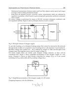
The motor drive system (Moog GmbH, ibid), used as the focus of investigation in the
mathematical development of the BLMD system based on physical principles, is shown in
Figure 1 and is typical of most high performance PM motor drives available. This drive system
is required for verification and validation of the BLMD modelling process at critical internal
observation nodes through comparison of experimental test results with model simulation
runs for accuracy. The servomotor system consists of a Power Supply Unit, Motor Controller
Unit and a PM brushless motor with component specification details as summarised in Table I.
The BLMD system, that is modelled here, has a considerable inverter dead time (20s) by
comparison with the nominal PWM switching period (200s). Each phase of the motor
stator winding has a separate PWM current controller with a 20s inverter delay for
Electric Vehicles – Modelling and Simulations
240
protection from current ‘shoot through’. This delay, which is dependent on the direction of
winding current flow, is manifested as a reduction in the overall modulated pulsewidth
voltage supply to the stator winding and developed motor drive torque. If the current flow
is directed into the phase winding then there is a reduction of 20s at the leading edge of the
modulated pulsewidth and if the current flow is negative an extension of 20s is appended
at the trailing edge of the modulated pulse. An accurate model of the BLMD system must
account for the presence of such a delay. During simulation of the BLMD model the current
flow direction has to be sensed to determine whether a fixed 20s delay pulse is to be
subtracted from or added to the modulated pulse duration. Detailed evaluation of the width
modulated pulse edge transition times is required for accurate BLMD modelling in such
circumstances in torque control mode to ensure numerical accuracy of PWM inverter
simulation and subsequent positioning of the inverter trigger delay associated with the large
dead time present. This is afforded by the use of small step sizes (~0.5%T
s
) by comparison
with the overall PWM switching period (T
s
) and application of the regula-falsi iterative
search method (Press et al, 1990) during BLMD simulation. Model accuracy is guaranteed
through numerical waveform simulation, which is shown to give excellent agreement in
terms of correlation with BLMD experimental test data at critical observation nodes for
model fidelity purposes. Consequently the BLMD model can be used for the specific
purpose of accurate simulation of circuit functionality within an actual typical EV motor
drive system with special emphasis on the inner torque loop as it embraces the PWM motor
current control operation with inverter delay during rapid EV acceleration.
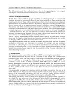
2.1 Overall system description
The 1.5 kW motor drive system, used as the subject of this BLMD modelling procedure,
has the component block diagram sketched in Figure 2. This system is an electronic self
commutated, PM synchronous machine (Tomasek, 1979), which is sinusoidally
controlled (Tomasek, 1986) and is typical of most high performance PM motor drives
available. The BLMD consists of a Power Supply Unit (PSU), Motor Controller Unit
(MCU) and a Brushless Servomotor with specification details itemized in Table I. The
PSU converts the matched three phase (3), 220V
rms
mains supply (U
s
) into a full wave
rectified stiff 310 volt dc supply (U
d
) with 18kW continuous power output thus
permitting multiple motor controller connection. A large smoothing capacitor maintains
a constant dc link voltage which provides a low impedance dc source for voltage-fed
inverter operation. The PSU can also fitted with an external dynamic braking resistor
which bleeds excess energy from the DC busbar U
d
during motor regeneration when the
ASD is overhauled by the rotor mechanical load. This resistor prevents overcharging of
the filter capacitor and thus a rise in the DC link voltage during rapid deceleration. The
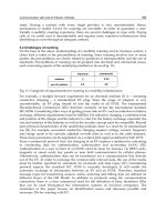
MCU contains the following functional elements, as depicted in Figure 3, which are
essential for proper operation of the brushless servomotor: (a) Power converter, (b) PWM
modulator, (c) Current controller, (d) 3 commutator, (e) Velocity controller and (e)
Circuit protection.
This provides brushless motor commutation and subharmonic PWM power control with a
30 Amp continuous output (o/p) current per phase to facilitate peak motor torque. The
controller outputs a synthesized variable frequency and variable amplitude 3 sinusoidal
current which accurately controls motor speed (n) and torque (). This is facilitated by a
configuration of six Darlington transistor-diode switches which form the three-leg inverter
amplifier shown in Figure 1.
Mathematical Modelling and Simulation of a PWM Inverter Controlled Brushless
Motor Drive System from Physical Principles for Electric Vehicle Propulsion Applications
241
M
oog Brushless Motor Drive System
L
1
L
2
L
3
Main
s
Matching
Transformer
PE
U
s
I
s
Controller
Unit T158
Command Signal
DC-Bus
Bleed Resistor
Power Supply
Unit T157
U
d
I
d
Brushless Servomotor
D314…L20
N S
Resolver
I
m
U
m
M, n
Sinusoidal
Distribution of
Stator Windings
High Energy
Sm-Co
5
PM
Rotor Poles
Cross-section of a 6-pole PM
MOOG Brushless Servomotor
Rotor
Stator Windin
g
Slots
Stator
Fig. 2. Typical BLMD system components (Moog, 1989)
Fig. 4. Motor cross section
Power Transistor
Brid
g
e
Pulsewidth
Modulation
PWM
Current
Controller
Protection
Lo
g
ic
Disable
Motor Current
Electronic
Commutato
r
Resolver
Signal
Converter
Encoder
Simulato
r
Digital (Absolute)
Rotor Position
Motor
Resolver
MOOG
Brushless
Servomotor
Torque
Limi
t
Velocity
Controlle
r
Thermal
Protection
Velocity Signal
Encoder Simulation (incremental)
Rotor
Position
Signal
Velocity
Command
D
ia
g
nostics
Enable
Transistor Bridge Temperature
DC-Bus +
D
C-Bus -
Motor
Thermistor
DC/DC
+15 V
0
-15 V
M
OOG Controller Uni
t
T158-012
Power Converter
Fig. 3. Block schematic of a typical BLMD controller module
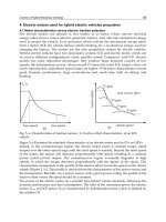
The brushless motor consists of a 12-pole PM rotor, a wound multiple pole stator, a 2-pole
transmitter type pancake resolver and a ntc thermistor embedded in the stator end turns with
a typical cross-section sketched in Figure 4. Stator current is provided by a 3 power cable
with a protective earth while a signal cable routes rotor position information from the pancake
resolver located at the rear side of the motor structure. The outer motor casing (stator) houses
the 3 stationary winding in a lamination stack. The Y-connected floating neutral winding is
embedded in slots around the air gap periphery with a sinusoidal spatial distribution. This has
the effect of producing a time dependent rotating sinusoidal MMF space wave centred on the
magnetic axes of the respective phases, which are displaced 120 electrical degrees apart in
space. The inner member (rotor) contains the Samarium-Cobalt magnets, which have a high
holding force with an energy product of 18 MGO
e
(Demerdash et al, 1980), in the form of arc
segments assembled as salient poles on an iron rotor structure. The fixed radially directed
magnetic field, produced by the rotor magnets, is held perpendicular to the electromagnetic
field generated by the stator coils and consequently yields maximum rotor torque for a given
stator current. This stator-to-rotor vector field interaction is achieved by electronic
commutation, which processes rotor position information from the shaft resolver to provide a
balanced three phase sinusoidal stator current. The high peak torque achievable, which is
Electric Vehicles – Modelling and Simulations
242
about eight to ten times the rated torque for Sm-Co
5
PM motors (Tomasek, 1983), and low
rotor inertia J result in high dynamic motor performance which is evident from the large
dynamic factor given in Table I. A high continuous torque-to-volume ratio is achieved due to
the high pole number in the motor stator.
2.1.1 General features of a typical BLMD system
A network structure for this BLMD system, showing the functional subsystems and their
interconnection into an overall organizational pattern, is illustrated in Figure 1A. This
provides indication of the type and complexity of model required as the first step in the
development of a comprehensive and accurate model for embedded system parameter
identification and EV performance evaluation. The dynamic system consists of an inner
current loop for torque control and an outer velocity loop for motor shaft speed control each
of which can be individually selected according to the control operation required. The major
functional elements of the system are:
a. a velocity PI control governor G
V
for wide bandwidth speed tracking. This compares
the velocity command V
with the estimated motor shaft velocity V
r
from the
resolver-to-digital converter (RDC) and from which an optimized velocity error signal
e
v
is derived.
b. a torque demand filter H
T
with limiter for command input
d
slew rate limitation and
circuit protection in the event of excessive temperature in the motor winding and MCU
baseplate.
c. a phase generation ROM lookup table which issues sinewaves corresponding to position
of the rotor magnetic pole. The phase angles are determined, with angular displacement
of 120 degrees apart, from the RDC position
r
for current vector I(t) commutation
d. a 3 commutation circuit for generation of variable frequency and variable amplitude
phase sequence current command signals. The command amplitudes are determined by
mixing the velocity error or torque demand with the phase generator output using an 8-
bit multiplying Digital-to-Analog Converter (DAC).
e. current command low pass filtering H
DI
for high frequency harmonic rejection.
f. current controllers G
I
which close a wide bandwidth current loop around three phases
of the motor winding in response to the filtered commutator current output. Current
feedback sensing from the stator windings is accomplished through Hall Effect Devices
(HED) which is then filtered (H
FI
) to remove unwanted noise.
g. a 3 pulse width modulator giving an output set of amplitude limited (V
S
) switching
pulse trains to drive the inverter power transistor bridge. The pulse aperture times are
modulated by the error voltages from the respective phase current controllers when
compared with a fixed frequency triangular waveform v
tri
(t).
h. RC delay networks which provide a fixed delay , related to the turn-off time of power
transistors, between inverter switching instants. These “lockout” circuits are necessary
during commutation of the inverter power transistors to avoid dc link short circuit with
current "shoot-through".
i. a six step inverter which consists of the PWM controlled three-leg power transistor
bridge and the base drive circuitry which include the switch delay networks. As the
motor rotates the commutation logic switches over the power transistor bridge legs via
the base drive circuits in a proper sequence. During a given commutation interval the
power transistor bridge is reduced to one of the three possible (a-b, a-c, b-c) two-leg
configurations. The PWM pulse trains are effectively amplified to the dc bus voltage
supply U
d
before application to the three phase motor stator windings.
Mathematical Modelling and Simulation of a PWM Inverter Controlled Brushless
Motor Drive System from Physical Principles for Electric Vehicle Propulsion Applications
243
Fig. 1A. Network structure of a typical brushless motor drive system (Guinee, 1998)
Torque
Demand
cos(pr)
cos(pr+2/3)
cos(pr-2/3)
Gv
3 Current
Current
Command
HDI
HDI
HDI
Current
Controller
Ida
Idb
Idc
G
I
G
I
G
I
+
+
+
-
-
-
Modulator
Tr iangular Car r ie r
Waveform Vtri
Vca
Vcb
Vcc
3 Delay
Network
C
BDC
TC+
TC-
TB +
TB -
TA+
TA-
B
A
BASE
DRIVE
BDA
BDB
Ud
Resolver
To Digital
Converter
(RDC)
IasIbsIcs
3Current
Feedback
Filter ing H
FI
Hall Effect
Device HED
Current
Feedback
I
fa
I
fb
I
fc
Phase Generator
ROM Table
Shaft
Velocity
Filter Hv
Position
r
Velocity Feedback
r
Velocity
V
d
Shaf t Position
Resolver
a
b
c
s
Lss
B RUSHLESS
DC MOTOR
3Stator
winding
Permanent
Magnet Rotor
p pole pair s
Shaft Inertia Jm
& Friction Bm
HT Busbar
PWM
INVERTER
rs
H
T
R
C
Vlc & Vlc
Vlb & Vlb
Vla & Vla
A
B
C
r
PWM
Commutation
Command
Filtering
Controller
Filte ring
Vsb
Vsa
Vsc
Vcg
Vbg
Vag
Electric Vehicles – Modelling and Simulations
244
j. an RDC (Figure 1A) which provides a 12 bits/rev natural binary motor shaft position
signal, with the 10MSB’s used for motor commutation, and an analogue linear voltage
signal proportional to motor speed
r
. The estimated speed signal is subsequently
filtered to give a velocity tracking signal V
r
which can be used for motor tuning via G
V
and performance evaluation.
k. a shaft velocity filter H
V
for speed signal noise reduction before feeding to the velocity
controller.
l. three phase motor with a high coercivity permanent magnet rotor.
2.2 Mathematical behavioural model of BLMD system
The behaviour of the BLMD system can be ascertained from physical principles in terms of
its electromechanical operation during energy conversion. The system operation is
described in terms of its Kirchhoff’s law voltage equations and electromagnetic torque
which are derived in subsequent sections. These equations can be used to
a. develop a complete mathematical model for the BLMD system whereby its performance
can be evaluated
b. understand and analyse the electomechanical energy conversion process in the PM
motor and
c. in system design techniques and optimization for specific requirements.
The result is a set of nonlinear equations describing the dynamic performance of the BLMD
system. The 3 motor stator windings are Y connected and are sinusoidally distributed with
an angular separation of 2/3 radians, associated with the mechanical location of the phase
coils, as illustrated in Figure 4. The rotor consists of p pairs of permanent magnet pole face
slabs, anchored to the solid steel shaft, which provide a sinusoidal magnetic flux
distribution vector (
r
) in the air gap between the rotor and stator. If the PM pole face
geometry admits to a nonuniform air gap then the reluctance variation, due to the effects of
rotor saliency, as a function of rotor position is generally considered in the evaluation of the
stator winding inductances. The effects of rotor saliency as shown in Figure 5, where the a
s
,
b
s
, c
s
and d axes denote the positive direction of the magnetic axes of the symmetrical
windings and PM poles in stationary (s) and rotating (r) coordinate reference frames, will be
included initially as a generalization of the analytical model of the BLMD system.
2.2.1 Stator winding flux linkages and inductances
Angular displacements can be referred to either the rotor or stator frames as shown in
Figure 5 with the interrelationship
srr
(I)
where
s
and
r
are the respective stator and rotor angular displacements referred to the a
s
axis.
The air-gap MMF space vector for the 3 distributed stator winding, with N
s
equivalent coil
turns per phase, can be written in terms of the space angle p
s
around the air gap periphery as
2
23
2
3
cos( )
,()cos()
cos( )
s
as s
N
sb bss
p
c
cs s
ip
tip
ip
as
s
s
s
(II)
Mathematical Modelling and Simulation of a PWM Inverter Controlled Brushless
Motor Drive System from Physical Principles for Electric Vehicle Propulsion Applications
245
a
4
*
a
3
*
a
2
*
a
1
*
b
4
b
3
b
2
b
1
c
1
c
2
c
3
c
4
a
3
a
2
a
1
b
4
*
b
3
*
b
2
*
b
1
*
c
1
*
c
2
*
c
3
*
c
4
*
a
4
d axis
q-axis
a
s
axis
c
s
axis
b
s
axis
N
S
r
r
Current Direction
r
s
e
L
Fig. 5. Salient 2-pole synchronous PM Motor with non-uniform air gap (Guinee, 2003)
The MMF standing wave, which is wrapped around the air gap periphery, is effectively
produced by a sinusoidally distributed current sheet located on the inner stator
circumference as shown in Figure 6 for phase-a. The standing space wave components are
modulated by the time varying balanced 3 stator current, with electrical angular frequency
e
, represented by
Phase-a MMF Wave
as
= (
N
s
/2
p
)
i
as
cos(
p
s
)
a
s
-
axis
Conductor Belt
Current Shee
t
s
N
s
/2
a
s
*
a
s
/2
-/2
Stator Conductor Belt
D
istribution
N
as
(
s
)
a
9
*
a
8
*
a
7
*
a
6
*
a
5
*
a
4
*
a
3
*
a
2
*
a
1
*
a
9
a
8
a
7
a
6
a
5
a
4
a
3
a
2
a
1
Fig. 6. Phase-a MMF standing space wave
2
3
2
3
cos( )
()
( ) cos( )
()
cos( )
me
bme
c
me
It
it
it I t
it
It
as
s
s
s
I t (III)
Electric Vehicles – Modelling and Simulations
246
These pulsating standing waves, with amplitudes proportional to the instantaneous phase
currents and directed along the magnetic axes of the respective phases, produce a travelling
MMF
S
wave that rotates counterclockwise about the air gap as a set of magnetic poles given by
3
2
,() cos( )
s
N
ss m e s
p
tIt
p
(IV)
with synchronous speed
se
d
r
dt p
(V)
The motor shaft also rotates at synchronous speed with the result that the stator MMF is
stationary with respect to the rotor. The length of the air gap g(
r
) between the rotor and
stator changes with rotor position
r
which for a 2p-pole rotor, using Figure 5, is given by
-1
12
() cos(2 )
rr
gp
with upper and lower bound limits given as
11
12 12
g
. Consequently this affects the reluctance of the flux path with a
cyclic variation that occurs 2p times during one period of revolution of the rotor. As a result
of reluctance variation, the inductances of the stator windings change periodically with PM
pole rotation. The net magnetic flux in the motor air gap can be regarded as a combination
of that due to the rotating armature MMF and a separate independent PM polar field
contribution. The effect of armature reaction MMF on the magnitude and distribution of the
air gap flux in a PM motor can controlled by altering the winding current using an electronic
converter which is self-synchronized by a shaft position sensor as in a BLMD system. The
corresponding flux density radial vector B
s
(
s
,
r
) contributions in the air gap can be
determined from the MMF for each phase acting separately due to its own current flow,
using Amperes’s magnetic circuit law, as
0
()
,
sr
as as
sr bs ab
gp p
cs cs
B
B
B
s
B
(VI)
The flux linkage
s
(
s
,
s
) of a single turn of a stator winding, which spans radians with
angular orientation
s
from the a
s
axis, can be determined by integration (Krause, ibid) as
/
,(,)
s
s
p
sr r
rld
ss
B (VII)
over the cyclindrical surface defined by the air gap mean radius r and axial length l. The flux
linkage of an entire stator phase winding, due to its own current flow, can be determined
from integration over all turns of a conductor belt with sinusoidal distribution N
s
(
s
) given
by
2
23
2
3
sin( )
sin( )
sin( )
s
s
as
N
sbs s
p
cs
s
p
N
Np
N
p
s
N
(VIII)
Mathematical Modelling and Simulation of a PWM Inverter Controlled Brushless
Motor Drive System from Physical Principles for Electric Vehicle Propulsion Applications
247
If linear magnetic structures are assumed for non saturated stator conditions the flux linkage
for phase-a, with similar calculations for the other two phases, is given by
2
/
0
2
01
22
() (,)
= cos(2 )
s
p
asas ls as as s as s r s
N
ls as r as
p
Li p N d
Li
p
rl
p
i
(IX)
where L
ls
is the leakage inductance. The second term in (IX), when divided by the current i
as
,
defines the phase-a winding self inductance
cos(2 )
asas ss G r
LLL p
(X)
with
2
01
2
s
N
ss
p
L
p
rl
and
2
1
02
22
s
N
G
p
L
p
rl
. This consists of the nominal
inductance L
ss
as the default value for round rotor geometry and the variable air gap
reluctance contribution which pulsates with amplitude L
G
with rotor position. Similar self
inductance expressions can be deduced for the other two phases, by allowing for the 120
phase displacement in the air gap reluctance contribution, as
2
3
2
csc
3
cos2( )
cos2( )
bsbs ss G r
sssG r
LLL p
LLL p
(XI)
The flux linkage contribution from mutual magnetic coupling between phases is obtained,
via (IX), by evaluating the flux linking of a particular phase winding due to current flow in
any of the two other phases. The magnetic interaction between phases a and b, for example,
is given by
2
2
012
22 3
2
1
23
() (,) =- cos(2 )
= - cos(2 )
s
N
asbs as s bs s r s r bs
p
ss G r bs
Nd
p
rl
p
i
LL p i
(XII)
with similar expressions for the other cross phase interactions. The corresponding mutual
inductance is determined as, upon dividing (XII) by i
bs
,
2
1
23
-cos(2)
asbs bsas ss G r
LL LL p
(XIII)
This consists of the nominal value (-L
ss
/2) normally associated with a uniform air gap or
round rotor and a variable component due to rotor saliency. The mutual inductance
components associated with other flux linkage phase interactions are reciprocal and are
similarly obtained with
2
1
23
1
2
-cos(2)
-cos(2)
ascs csas ss G r
bscs csbs ss G r
LL LL p
LL LL p
(XIV)
The cumulative flux linkage for each of the three phases, using (IX) and (XII) as examples for
phase-a, may be expressed as
Electric Vehicles – Modelling and Simulations
248
(, )
T
rasbscs
s
I
(XV)
with
csc
as asas asbs ascs asm ass asm
bs bsas bsbs bscs bsm bss bsm
cs csas csbs s csm css csm
where {
asm
,
bsm
,
csm
} represent the PM rotor phase-flux linkages which have a 120 relative
phase disposition and {
ass
,
bss
,
css
} are the 3-phase armature reaction flux linkages. The
general form of the flux linkage expression (XV) can be evaluated, via (IX) and (XII), using
numerical integration techniques without resorting to the linear magnetic circuit constraint.
This approach is relevant only when magnetic saturation is an issue during very high
current demand in peak torque applications. In this instance the time varying inductances,
associated with salient PM rotor rotation, are nonlinear with values that depend on the
saturation status of the armature iron. However the assumption of linear magnetic
structures greatly simplifies the modelling process with considerable savings in numerical
computation. This assumption is applicable in the absence of magnetic saturation and can be
used to provide a very good model approximation with negligible error during brief periods
of magnetic saturation associated with over current drive. The total magnetic flux vector
s
(I,
r
) may be rewritten in terms of winding inductance matrix L
s
(
r
), stator current I
s
(t) and
rotor field coupling
sm
(
r
), for linear magnetic operation, as
csc
as ls asas asbs ascs as asm
bs bsas ls bsbs bscs bs bsm
cs csas csbs ls s cs csm
LL L L i
LLLLi
LLLLi
(XVI)
This can also be expressed in the compact matrix form as
(,) (,) () ()() ()
rrrr r
t
ssssmsssm
I
ILI
(XVII)
with total flux
(, )
rasbscs
s
I , rotor flux
22
33
( ) sin( ) sin( ) sin( )
T
T
r asm bsm csm m r m r m r
pp p
sm
and stator
flux
(, ) ( ) ()
r ass bss css r
t
T
ss s s
I=LI
Since the machine windings are
Y-connected the algebraic sum of the branch currents is zero
with
0
as bs cs
iii
(XVIII)
and the flux linkage equation (XVI) can be written in terms of the symmetric inductance
matrix as
22
33
22
33
2 2
3 3
cos(2 ) cos(2 ) cos(2 )
cos(2 ) cos(2 ) cos(2 ) .
cos(2 ) cos(2 ) cos(2 )
ls s G r G r G r
as as
bs G r ls s G r G r bs
cs cs
Gr Gr lssGr
LLLp Lp Lp
i
Lp LLLp Lp i
i
Lp Lp LLLp
asm
bsm
csm
(XIX)
Mathematical Modelling and Simulation of a PWM Inverter Controlled Brushless
Motor Drive System from Physical Principles for Electric Vehicle Propulsion Applications
249
where L
s
is the synchronous inductance for a non salient rotor given by
3
2
sss
LL . If leakage
inductance is neglected and a round rotor structure is assumed the inductance variation L
G
in (XIX) disappears with the elimination of the air gap factor
2
. This results in the
synchronous inductance matrix, which is diagonal, with constant entries L
s
.
The phase voltage equations governing the BLMD electrical behaviour can be determined
from the stator winding flux linkages using Faraday’s law as follows
(,) () ( ) ( )
() () () ( ) ()
rr
dIt dt d d
r
dt dt dt dt
tt t t
ss
IL
s
V
s sm
ss ss s s
RI RI L I (XX)
which phase index notation change {1 a; 2 b; 3 c} where
V
s
(t) = [ v
1s
(t) v
2s
(t) v
3s
(t)]
T
,
I
s
(t) = [ i
1s
(t) i
2s
(t) i
3s
(t)]
T
, R
s
= diag[r
s
] and r
s
is the phase winding resistance and L
S
(
r
) is the
time varying inductance matrix in (XIX).
2.2.2 Phase voltage equations in the stator reference frame
The voltage expression (XX) in stationary coordinates is used to determine the phase voltage
differential equations based on the assumption of a round rotor structure as follows:
(,)
for 1,2,3
js js r
di
js s js
dt
vri j
(XXI)
The total mutual air gap magnetic flux for phase-j given by
(,) (,) () ()
j
s
j
sr
j
ss
j
sr m
j
rs
j
sm
j
r
ii Li
(XXII)
where
2( 1)
3
() sin( )
j
mj r m r
p
.
Expression (XXI) may be rewritten as
for 1,2,3
js s js s js ej
v r i L di dt v j
(XXIII)
where v
ej
is the internally generated phase-j back emf voltage given by
2( 1)
3
cos( )
j
ej e r r
vK p
(XXIV)
with motor voltage back EMF constant K
e
given by
em
Kp
and rotor shaft velocity
r
as in
(V). The alternative compact matrix form for (XXIII) is given by
11 1
2
22 2
3
2
33 3
3
cos( )
00 0 0
00 0 0 cos( )
00 0 0
cos( )
r
ss s lss s
d
sss lss ser
dt
sss lsss
r
p
vr iLL i
vri LL iKp
vri LLi
p
(XXV)
The uniform air gap assumption results in a diagonal inductance matrix, which allows for
current variable decoupling in (XXV) and thus a tractable model structure. This approach is
somewhat justified, in the absence of magnetic saturation, from previous studies (Persson et
al, 1976; Demerdash et al, 1980) where the independence of stator inductance with salient
Electric Vehicles – Modelling and Simulations
250
rotor displacement has been explained. The raison d’être of this simplifying assumption is
that the permeability of the magnetically hard Samarium-Cobalt (SmCo
5
) material is almost
equal to that of air. As a consequence of this property the SmCo
5
material has some desirable
features from a BLMD modelling perspective in terms of its intrinsic demagnetization
characteristic. The PM rotor air gap line (Matsch, 1972) is a design feature which is
optimized in terms of the maximum energy product of 160 kJm
-3
(Crangle, 1991) for a given
machine configuration and magnet geometry. In Figure 7 the locus of operation of the air
gap line, due to changes in gap width, is a minor hysteresis loop (Match, ibid) with axis
tangent to the magnetization curve through the retention flux
0
.
B
Retentivity
B
R
Flux
0
Air gap Lines
g
max
g
min
H
Coercitivity
H
c
(
B
,
)
Intrinsic Demagnetization
Characteristic
B
ma
x
BH
E
ner
gy
Produc
t
Characteristic
B
H
max
Fig. 7. PM flux variation with air gap width
The corresponding oscillating PM flux variations , which occur p times per rotor
revolution, are practically negligible (
0
) with little impact on the overall rotor flux
linkage contribution to the stator windings.
H
c
max
B
Retentivity
{
B
R
,
0
}
Retentivity
{
B
R
,
0
}
Air gap Line
Intrinsic Demagnetization
Characteristic
2
3
1
D
emagnetizing Field
H
H
ysteresis Loop
Fig. 8. Demagnetizing MMF effect
Mathematical Modelling and Simulation of a PWM Inverter Controlled Brushless
Motor Drive System from Physical Principles for Electric Vehicle Propulsion Applications
251
In Figure 8 the repeated application of a demagnetizing MMF, generated by the stator
windings, results in a negligibly small flux variation (
0
) associated with the minor
hysteresis loop on the demagnetization curve. The applied radial stator H-field, which is
designed to lie on the knee of the intrinsic demagnetization characteristic (Pesson et al, 1976)
corresponding to the energy product figure BH
max
, has its maximum value associated with
the air gap line at H
max
. Since the PM relative permeability (
r
) is almost unity, the applied
field generated in the stator windings is not affected by rotor position.
2.2.3 Electromechanical energy conversion and torque production
In a BLMD system the electromechanical energy conversion process involves the exchange of
energy between the electrical and mechanical subsystems through the interacting medium of a
magnetic coupling field. This energy transfer mechanism is manifested by the action of the
coupling field on output mechanical motion of the rotor shaft masses and its stator winding
input reaction to the electrical power supply. This reaction, which is necessary for the coupling
field to absorb energy from the electrical supply, is the emf V
s
(t) induced across the coupling
field by the magnetic field interaction of the stator winding with the PM rotor. Energy
conversion during motor action is maintained by the incremental supply of internal electrical
energy dW
e
, associated with sustained current flow I
s
(t) against the reaction emf, to balance the
differential energy dW
f
absorbed by the reservoir coupling field and that released by the
coupling field dW
m
to mechanical form. This results in the replenished energy transfer for
sustained motion with stator flux change d
s
(I,
r
), using (V), as
*
e
ttdt td(,)
ss s sr
f
m
dW I V I I dW dW
(XXVI)
where mechanical and field losses are included in the electrical source V
s
(t) and are thus
ignored for convenience. In a motor system most of the stator winding MMF is used to
overcome the reluctance of the air gap separating the fixed armature from the moving rotor
in the magnetic circuit. Consequently most of the magnetic field energy is stored in the air
gap so that when the field is reduced most of this energy is returned to the electrical source.
Furthermore since stacked ferromagnetic laminations are used in the stator winding
assembly the magnetic field core losses are minimal whereupon the magnetic coupling
fields are assumed conservative. The field energy state function W
f
(
1s
,
2s
,
3s
,
r
) can be
expressed in terms of the flux linkages (
1s
,
2s
,
3s
) in (XVI), for multiple stator winding
controlled excitations with appropriate index change, and the mechanical angular
displacement
r
of the rotor. This can be expressed in differential form using (XXVI) in terms
of the stator winding flux linkages
js
and currents i
js
as
33
11
ff
js r
WW
fj
sr
j
s
j
sm
jj
dW d d i d dW
(XXVII)
The mechanical energy transfer
dW
m
with incremental change d
r
in rotor position
r
due to
developed electromagnetic torque
e
(I
s
,
r
) by the coupling field is expressed by
,
me rr
dW d
s
I
(XXVIII)
By coefficient matching the state variables
r
and
js
for j{1,2,3} in (XXVII) and (XXVIII) an
analytical expression for the electromagnetic (EM) torque
e
is obtained with
r
rf
W
re
),(
),(
s
s
. (XXIX)
Electric Vehicles – Modelling and Simulations
252
in terms of the coupling field stored energy as a function of the flux linkages
s
. The
coupling field energy is first determined by integration of the other coefficient partial
differential equations
}3,2,1{
),(
ji
js
rf
W
js
s
(XXX)
with respect to the flux linkages of the connected system for restrained rotor conditions as
,,,),(
3
1
321
),(
)0(
s
j
rsssjsjsjs
j
W
d
rf
iiididW
js
rf
r
s
(XXXI)
as shown in Figure 9 before evaluation of the drive torque. Since the flux linkages are
functions of the stator winding current, complex and lengthy numerical integration of (XXX)
would be required over the nonlinear
-i magnetization characteristic in Figure 9, which
must be known, if saturation effects are to be included. However if magnetic nonlinearity is
neglected, with the assumption that the flux linkages and MMFs are directly proportional
for the entire magnetic circuit as in air, the resulting analysis and integral expression (XXXI)
is greatly simplified. In this case the flux linkages are assumed to be linear with current
magnitude, which is often done in the analysis of practical devices, in the winding
inductances as in (XXII). However a simpler and more convenient alternative (Krause, 1986)
than obtaining the EM torque as a function of
s
via W
f
(
s
,
r
) in (XXXI), relies on the
coenergy state function
W
c
(I
s
,
r
) to determine the applied torque
e
in terms of the stator
currents
I
s
as the independent PWM controlled state variables in BLMD system operation.
This methodology is more effective during BLMD model simulation as the motor winding
currents are immediately available for motor torque computation.
di
js
i
j
s
js
E
nergy
W
f
Coenergy W
c
M
agnetization
Characteristic
d
js
js
i
js
Fig. 9. Stored energy and coenergy
The coenergy
W
c
(I
s
,
r
), which has no physical basis or use other than to simplify the torque
calculation, is the dual form of the coupling field energy
W
f
(
s
,
r
) as shown in Figure 9 with
rf
T
rc
WW
,
ˆˆ
,
ssss
II (XXXII)
Mathematical Modelling and Simulation of a PWM Inverter Controlled Brushless
Motor Drive System from Physical Principles for Electric Vehicle Propulsion Applications
253
The following equivalent expressions result for the differential forms of the coenergy in
(XXXII) using the substitutions (XVII) and (XVIII) for
W
f
(
s
,
r
)
33
11
(,) ,
cr
j
s
j
s
j
s
j
s
j
s
j
se rr
jj
dW i d di i d d
ss
II
(XXXIII)
3
1
,
cc
js r
WW
cr
j
sr
i
j
dW di d
s
I (XXXIV)
which when coefficient matched yield the parametric equations
,
j {1,2,3}
cr
W
js
s
js
I
i
(XXXV)
,
,
cr
r
W
er
s
I
s
I . (XXXVI)
The coupling field coenergy is determined from (XXXV) by integrating the cumulative stator
flux linkages in (XV) with respect to the appropriate phase currents for restrained rotor
movement as
,
33
,
11
WI
csr
W I di di
csr
jj
s
jj
s
j
s
i
js
(XXXVII)
If magnetic nonlinear saturation effects and field losses are negligible then the flux linkages
are linearly related to the currents, which establish the magnetic coupling field, through the
inductance circuit elements as in (XIX) for a salient pole rotor with
3
1
()
j
s
j
kks
j
m
k
Li
(XXXVIII)
The resulting coenergy W
c
, from substitution of (XXXVIII) into (XXXVII), is given by
333 3
2
1
1
2
11 1
0
,
r
k
cr
jj j
s
j
kks
j
s
j
m
j
s
jj j
d
kj
WLiLiii
s
I
(XXXIX)
from which the EM torque is evaluated using (XXXVI) as
2
1
333 3
,
11 1
1
2
dL dL d
jj jk jm
iiii
er jjs j ksjs jjs
k
ddd
rrr
kj
I
s
(XL)
This may be expanded in terms of the stator winding inductances for a salient pole machine as
33
2( 1)
2( 1)
2
1
33
1
3
2( 1)
3
1
,sin2 2sin2
cos
j
k
k
er G r
j
srks
j
s
j
kj
j
trjs
j
p
Lpi pii
Kp i
s
I
(XLI)