Photodiodes Communications Bio Sensings Measurements and High Energy Part 8 pot
Bạn đang xem bản rút gọn của tài liệu. Xem và tải ngay bản đầy đủ của tài liệu tại đây (3.08 MB, 20 trang )
A Photodiode-Based, Low-Cost Telemetric- Lidar
for the Continuous Monitoring of Urban Particulate Matter
131
continuous monitoring of the laser power. This data was stored together with the other
LIDAR data, and was used for the normalization of the LIDAR data (eq.6). In the case of a
laser failure, an E-mail message was automatically sent to IFAC. On-board meteorological
sensors for wind, relative humidity, and temperature completed the instrumentation.
Meteorological data were managed and stored together with the other data. All data were
sent via FTP to IFAC at the end of each day.
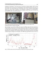
Fig. 12. The instrument opened (left) and installed on the roof of the ARPAT, PM-
monitoring station in Florence (I) (right)
This prototype was installed in 2006 on the roof of an ARPAT station (Via Ponte alle Mosse,
Florence (Italy), where it was in operation until the end of 2007. The instrument operated on
a 45° slant above the horizon, for a fixed measurement distance of 8(±1) meters. ARPAT
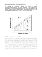
provided daily gravimetric PM10 data. In Fig.13, a time series of one month of telemetric-
LIDAR data is compared with gravimetric PM10 data. The upper plot shows the LIDAR
calibrated signal averaged over 10 minutes. The PM10 daily gravimetric data are shown as
Fig. 13. PM10 as derived from the telemetric-LIDAR and from gravimetric data.
Photodiodes – Communications, Bio-Sensings, Measurements and High-Energy Physics
132
symbols. The ARPAT monitoring station collected PM10 and PM2.5, alternatively, for 15-
day periods. Black stars indicate genuine PM10 measurements, while green stars indicate
PM10 values calculated from PM2.5 data by applying a constant, empirical factor of 1.4, as
suggested by ARPAT.
Until December 14 the diurnal cycle of PM, related to traffic, is evident in the telemetric-
LIDAR data. During the 14-21 December period, northern winds cleaned-up the PBL
(Planetary Boundary Layer) (Stull, 1988) and prevented the formation of inversion layers,
thus reducing the PM10 and cancelling its diurnal cycle. During the 22-26 December period,
a strong thermal inversion occurred, which led to high PM10 concentrations. The
comparison between the LIDAR-derived and gravimetric data was unfortunately
undermined by the different time resolutions of the two types of measurements. The LIDAR
information had to be degraded to 24-hour averages in order to compare it with the daily
gravimetric data, the only official information available in many Italian towns. The said
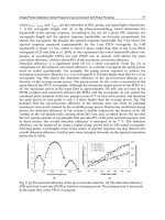
comparison was used to obtain an empirical system calibration, as shown in Fig.14.
Fig. 14. Correlation between LIDAR-derived and gravimetric PM10 values. 24-hour
averages. The Pearson linear correlation coefficient is R= 0.89, p<0.001. The experimental
calibration factor for the telemetric-LIDAR is reported.
5. Conclusions
We described an application for a Silicon photodiode array consisting in a low-cost, rugged
instrument for the continuous remote monitoring of urban particulate matter (PM). The
experimental tests confirmed the optical and electronic simulations, which suggested the
possibility of measuring PM in the urban environment 24 hours/day within a range of
several tens of meters, with a time resolution of 5-10 minutes. The instrument is a candidate
tool for complementing ordinary gravimetric PM10 measurements, with the advantage of
offering a high temporal resolution and the absence of pumps or other moving parts. The
instrument was found to be suitable for unattended operation and much less expensive than
A Photodiode-Based, Low-Cost Telemetric- Lidar
for the Continuous Monitoring of Urban Particulate Matter
133
any ordinary PBL LIDAR. When used within a range of a few tens of meters, thanks to its
high spatial resolution the instrument could be utilised for the continuous remote
monitoring of PM emitted by smokestacks, power plants, and in all those cases in which the
relative humidity is non-saturating and the typology of the emitted particles is known.
6. References
Bucholtz A. (1995). Rayleigh-scattering calculations for the terrestrial atmosphere, Appl. Opt.
34, pp 2765-2773,
ISSN: 1559-128X
Collis R.T.H.,Russell P.B. (1976), Lidar measurement of particles and gases by elastic
backscattering and differential absorption,In:
Laser Monitoring of the Atmosphere,
Topics in Applied Physics Vol. 14, Hinkley Ed., pp. 71–151, Springer, ISBN
038707743X, Berlin
Duclaux. (1936), J. Phys. Radiat. 7, S. 361. Referenced in: P.S. Argall, Sica R.J., LIDAR
In:
Hornak J.P.,( 2002),
The Encyclopedia of Imaging Science and Technology, Wiley, ISBN:
978-0-471-33276-3, New York
Measures R.M. (1988).
Laser remote chemical analysis, John Wiley & Sons Eds., ISBN:
047181640X, New York
Meki K. (1996). Range-resolved bistatic imaging LIDAR for the measurement of the lower
Atmosphere,
Opt. Lett . 21,17, pp.1318-1320,(1996), ISSN 0146-9592
Del Guasta M. (2002). Daily cycles in urban aerosols observed in Florence (Italy) by means of
an automatic 532-1064 nm LIDAR.
Atmos. Env. 26, pp. 2853-2865, ISSN1352-2310
Del Guasta M., Marini S. (2000). On the retrieval of urban aerosol mass concentration by a
532 and 1064 nm LIDAR,
J. of Aerosol Sci. , 31, 12, pp. 1469-1488, ISSN0021-8502
Graeme J.G. (1996).
Photodiode Amplifiers: op amp solutions, Chp.5, McGraw-Hill Professional
Publ., ISBN 0-07-024247-X
Horowitz, P.&H., Winfield J.(1989).
The Art of Electronics. pp.1032-1033, Cambridge
University Press. ISBN 0-521-37095-7, New York
John W., Wall S.M., Ondo J.L., Winklmayr W. (1990). Modes in the size distributions of
atmospheric inorganic aerosols.
Atmos. Environ. 24, 9, pp.2349-2359, ISSN1352-2310
Kent G.S. (1978). Deduction of aerosol concentrations from 1.06 µm lidar measurements.
Appl. Opt. 12, 23, pp. 3763-3773, ISSN: 1559-128X
McMurry P.H., Stolzenburg M. (1989). On the sensitivity of particle size to relative humidity
for Los Angeles aerosols.
Atmos . Environ., 23, pp. 497-507, ISSN: 1352-2310
Penndorf, R. (1957) Tables of the refractive index for standard air and the Rayleigh
scattering coefficient for the spectral region between 0.2 and 20.0 um and their
application to atmospheric optics,
J. of the Optical Soc. Of America, Vol.47, N°2,
pp.176-182, ISSN 0036-8075
Porter, J. N., Lienert B. R., Sharma S. K., Hubble H. W., (2002). A Small Portable Mie–
Rayleigh Lidar System to Measure Aerosol Optical and Spatial Properties.
J. Atmos.
Oceanic Technol.
, 19, pp 1873–1877. ISSN: 0739-0572
Stull R.B. (1988)
An introduction to boundary layer meteorology, Kluwer Academic Publishers.
ISBN 90-277-2768-6, Dordrecht (NL)
Photodiodes – Communications, Bio-Sensings, Measurements and High-Energy Physics
134
Tatsumi K. Tadashi I . (1999). Characteristics of Lidar Signal Using Silicon Avalanche
Photodiode Single Photon-Counting Module.
Rev. of Laser Engin.27;3;pp 190-193,
ISSN 0387-0200
Van de Hulst H.C., (1998).
Light scattering by small particles, Wiley & sons Inc., ISBN
0471293407, New York
Part 3
Photodiodes for Biomedical Application
8
The Photodiode Array: A Critical
Cornerstone in Cardiac Optical Mapping
Herman D. Himel IV
1
, Joseph Savarese
2
and Nabil El-Sherif
2,3
1
Duke University, Durham, NC
2
VA New York Harbor Healthcare System, Brooklyn, NY
3
Downstate Medical Center, State University of New York, Brooklyn, NY
USA
1. Introduction
The human heart pumps oxygenated blood to the organs and extremities in order to
maintain normal physiologic function, while simultaneously pumping deoxygenated blood
to the lungs for reoxygenation. Coordinated contraction of individual cardiac myocytes
provides the mechanical force necessary to produce sufficient pressure and ensure that
distant organs and extremities remain oxygenated. Before cardiac myocytes may contract,
they must undergo excitation in order to begin the sequence of events which results in an
intracellular calcium (Ca
i
) rise, which in turn precipitates actin-myosin binding and
ultimately results in contraction. The electrical signature of this series of events is reflected
in the cardiac action potential (AP), a segment of a transmembrane voltage (V
m
) recording
which indicates electrical excitation (depolarization) and relaxation (repolarization) of the
myocardium.
The duration, amplitude, upstroke velocity (dV
m
/dt), and overall morphology of the cardiac
AP are important markers of the electrical status of the heart. Studies of the cardiac AP have
provided important insights into the mechanisms which drive the transition from a normal,
healthy heartbeat toward a deadly cardiac arrhythmia.
Early recordings of the cardiac AP were obtained using microelectrodes (Coraboeuf &
Weidmann, 1949a; Coraboeuf & Weidmann, 1949b; Draper & Weidmann, 1951; Sano et al.,
1959; Sano et al., 1960; Weidmann, 1951). Although this method was highly effective in
tracking temporal changes in the V
m
of individual cells, the method could not be easily
applied to the problem of tracking excitation over a region of tissue. Extracellular electrode
mapping offered a partial solution to this problem and was sufficient to determine
activation times in regions of tissue, but with this method the details of repolarization were
lost and had to be estimated using indirect indicators. Further, this method required that the
electrodes be in direct contact with the tissue. This made defibrillation studies difficult, since
large amplitude defibrillation shocks typically obscure the details of activation during
electrical recordings. Monophasic action potential (MAP) recordings were capable of
elucidating the details of repolarization without damaging tissue, and have even been
recorded in the beating human heart using a cardiac catheter (Shabetai et al., 1968).
However they too were restricted by having little or no spatial resolution and could not be
Photodiodes – Communications, Bio-Sensings, Measurements and High-Energy Physics
138
placed in close contact with each other. As with extracellular electrodes, MAP recordings
also require that the electrodes be placed in contact with the tissue.
With the emergence of V
m
-sensitive dyes in the 70’s, it became possible to interrogate
cardiac tissue optically (Salama, 1976), and soon afterward optical methods were
developed to interrogate multiple spots simultaneously in a small (~cm
2
) region of tissue.
Since then the field of cardiac optical mapping (COM) has greatly expanded in scope,
from relatively simple early recordings using one or relatively few spots (Morad & Dillon,
1981; Salama, 1976) to highly complex optical systems. These include high spatiotemporal
resolutions systems (Choi et al., 2007), panoramic systems (Kay et al., 2004; Rogers et al.,
2007), and systems which are capable of interrogating electrophysiological activity
beneath the surface (Byars et al., 2003). In addition, several labs have used photodiode-
based optical mapping systems to map V
m
and Ca
i
simultaneously, on both the whole
heart (Choi & Salama, 2000; Lakireddy et al., 2006; Laurita & Singal, 2001; Pruvot et al.,
2004) and in monolayer cell cultures of cardiac myocytes (Fast, 2005; Fast & Ideker, 2000;
Lan et al., 2007).
Cardiac optical mapping systems have greatly increased our understanding in nearly all
areas of cardiac electrophysiology, from basic studies of conduction patterns (Cabo et al.,
1994; Knisley & Hill, 1995) and effects of fiber geometry (Knisley & Baynham, 1997; Knisley
et al., 1994; Knisley et al., 1999; Neunlist & Tung, 1995) to more clinical studies of
defibrillation (Al-Khadra et al., 2000; Fast et al., 2002; Federov et al., 2008; Tung & Cysk,
2007) and ablation therapy (Himel et al., 2007; Perez et al., 2006). Although COM has not yet
led to a widely accepted method of three-dimensional cardiac tissue interrogation, there
have been significant advances in this area as well. Investigators have successfully used
optical surface recordings to determine wavefront orientation beneath the surface (Hyatt et
al., 2005; Zemlin et al., 2008), and also to interrogate deeper layers of tissue using
transillumination methods (Baxter et al., 2001) and deeper-penetrating, near-infrared
fluorescing dyes (Matiukas et al., 2006; Matiukas et al., 2007; Salama et al., 2005).
Photodiode sensors were used in some of the earliest optical recordings of cardiac APs
(Morad & Salama, 1979; Salama, 1976), and continue to be used today (Cheng, 2006; Sakai,
2008). Photodiodes function by transferring incoming photonic energy to bound electrons in
a semi-conductive material in a transistor configuration. These energized electrons may then
cross from one side of the transistor to the other, resulting in a voltage difference between
the two sides.
If a wire is connected from one side of the photodiode to the other while the photodiode is
receiving photonic energy, current will flow in a linear fashion with respect to the input
intensity of the collected light (Scherz, 2007). This makes photodiodes an excellent choice as
a detector in COM systems, and this fact has been reflected by their widespread use over the
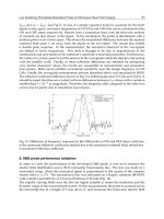
past 30 years. Examples of optical APs and activation maps recorded with a photodiode
array-based system are shown in figure 1.
Although other technologies such as CMOS and CCD cameras have recently gained
popularity due to their higher spatial resolution, photodiode systems remain in use due to
their ruggedness, high signal-to-noise ratios, excellent temporal resolution, versatility, and
low cost. Recently, for example, photodiodes and photodiode arrays (PDAs) have been used
in the construction of optrodes, a novel technique used to record optical signals from deeper
intramural regions within the ventricular wall (Byars et al., 2003; Caldwell et al., 2005;
Hooks et al., 2001; Kong et al., 2007).
The Photodiode Array: A Critical Cornerstone in Cardiac Optical Mapping
139
Fig. 1. APs and activation maps for normal and irregular rhythms. For rows A and B, the
horizontal bar beneath each recording indicates 1 second. Row A shows APs recorded
during basic rhythm. Row B shows APs occurring with irregular diastolic intervals,
followed by a long run of a ventricular tachyarrhthmia, triggered by the AP marked with an
asterisk. The two rows in section C show a sequence of activation during basic rhythm,
while the two rows in section D show a sequence of activation which took place during a
premature beat which precipitated a sustained ventricular tachyarrhythmia (note the
presence of two distinct activation sites). Frames are read from left to right, and then top to
bottom. Each successive frame is 1 ms apart. Lighter areas on the map indicate tissue
undergoing activation.
Photodiodes – Communications, Bio-Sensings, Measurements and High-Energy Physics
140
2. Basic principles of cardiac optical mapping
Epi-illumination occurs when the fluorescence emission detector is placed on the same side
of the tissue as the excitation source, whereas with trans-illumination the detector and
excitation source are placed on opposite sides. For monolayer mapping systems, both epi
and trans-illumination are possible since cardiac monolayers are typically only a few tens of
micrometers thick. For whole-heart mapping systems which map excitation on the surface
of the intact heart preparations, epi-illumination is the preferred method since very little
fluorescence is transmitted through the relatively thick myocardial wall.
The tissue being mapped must be illuminated using an excitation source, which excites at
least one parameter-sensitive dye in order to elicit a fluorescent signal. Changes in a
targeted physiological parameter cause changes in the properties of the dye (e.g., a
conformational change in the dye molecules). This results in a change in the emission
spectrum of the dye, which is then recorded by a detector (e.g., a PDA), digitized, and stored
on a PC for post-experimental analysis.
Changes in fluorescence due to changes in the physiological parameter are often measured
as a fraction of the baseline fluorescence. This is an important parameter in optical mapping,
and is known as fractional fluorescence (ΔF/F). Fractional fluorescence is useful because it is
a way to measure the effectiveness of a particular dye in transducing a physiological change
into recordable fluorescent signal. Fractional fluorescence also indicates the general
effectiveness of the system, and higher ΔF/F values are typically accompanied by higher
signal-to-noise ratios. Transmembrane voltage is the most commonly studied physiological
parameter in optical mapping, but intracellular calcium transients (Ca
i
T) have also been
studied extensively.
There are several variations of the COM system, however there are basic components that
are common to all systems. These basic components include an excitation source, detector,
and electronic components used for digitization, filtration, and multiplexing. A schematic
for a typical whole-heart mapping system is shown in figure 2.
2.1 Excitation source
The excitation source may be either focused (i.e. laser light) or broadfield illumination
(using halogen, tungsten, or more recently, high-power LED sources). Laser and some LED
light sources have sufficiently narrow bands so as not to interfere with the fluorescence
emission, however broadfield sources should be pre-processed using optical filters in order
to decrease the width of their wavelength spectrum before illuminating the target (e.g., the
heart). In general, brighter excitation sources lead to higher ΔF/F values, however the
intensity of the excitation source cannot be increased without regard for photobleaching,
which occurs when the dye emission decreases in intensity due to overexposure to
excitation light (Knisley et al., 2000; Kong et al., 2003). A highly stable source is superior to a
brighter but noisier source, since the stable source yields greater S/N ratios while allowing
longer duration recordings.
2.2 Detector
There are several types of detectors that are currently in use for COM, however the focus of
this review is upon those detectors which are photodiode-based. Other detector types will
be discussed for the purpose of comparison.
The Photodiode Array: A Critical Cornerstone in Cardiac Optical Mapping
141
Fig. 2. Top-down view of a typical PDA-based optical mapping system. The thin rectangular
boxes marked A, B, and C represent fluorescence band pass, long pass, and excitation band
pass filters, respectively. The long pass filter B is housed in an optical cube. The elliptical
shape between A and B represents a condensing lens. The front view of the PDA shows the
16x16 element photoactive region of the detector. The oval-like shape marked D represents
the heart, which is pressed against a flat plate in order to create a two-dimensional surface
so that the entire mapped region lies within the focal plane. Electrically connected
components are separated by a thin solid line, while optically connected components are
separated by hollow rectangles.
Photodiodes – Communications, Bio-Sensings, Measurements and High-Energy Physics
142
Current alternatives to PDAs include photomultiplier (PMT) systems, charge-coupled
device (CCD) cameras, and complimentary metal-oxide semiconductor (CMOS) cameras.
PMT systems have an extremely high gain (up to 10
8
increase in intensity), and can even be
used in a process call “photon counting” whereby the release of individual photons may be
recorded. PMT systems are capable of extremely high sensitivity, and typically have a
quicker response time than photodiode systems. However for normal optical mapping
applications, the sensitivity and response time of photodiodes is more than sufficient.
Typically, PMT systems employ sequential rather than simultaneous recordings of adjacent
spots. However, due to their rapid response time they may be coupled with a laser scanner
to produce acquisition rates equivalent to those seen in photodiode-based systems. For
example, a laser scanner which scans at 256 kHz with a 256-spot grid is essentially
equivalent to a PDA-based 256-spot system which scans at a rate of 1 kHz. For this example,
there will be a time difference of ~1 ms between the 1
st
and 256
th
spots scanned. This
difference can often be neglected during normal propagation in cardiac tissue. The basis for
the photomultiplier tube is the photoelectric effect, whereby an incident photon strikes a
photocathode and starts a chain reaction. The photocathode emits an electron, which strikes
subsequent dynodes, at each step of the way releasing a greater number of electrons than
those which struck the preceding dynode. At the final anode, the signal has been
"multiplied" many fold (~10
6
) and the resultant electrons result in a change in voltage.
Cameras using CCD technology typically have impressive spatial resolution, however these
systems have not been able to achieve the same temporal resolution as PDA-based systems.
The CardioCCD-SMQ (RedShirt Imaging, Decatur, GA) currently offers a spatial resolution
of 80x80 while achieving a temporal resolution of 2000 frames per second (fps). The CCD
camera may achieve higher temporal resolution and/or higher signal-to-noise ratios by a
process known as “binning,” however this process decreases the spatial resolution of the
camera, the major advantage of CCD technology. When using the CCD camera for cardiac
mapping experiments, light saturation of the detector may be an issue and thus gain must
be carefully controlled. Typically this is less of a problem with PDA systems. The basis of
operation of the CCD detector is a shift registration process. Charge which is accumulated
due to photons falling upon light-sensitive regions within the detector is transferred along
the 2-dimensional detector array until the charge within a given potential well reaches the
final readout electrode. The transfer of charge is accomplished by changing the voltage in an
adjacent pixel, causing electrical charge to flow in the desired direction.
Although more costly than either CCD cameras or PDAs, the CMOS camera boasts exciting
technology that has recently become capable of delivering extremely high spatiotemporal
resolution. RedShirt Imaging lists the CardioCMOS-128f as being capable of recording
128x128 spots at an acquisition rate of 10,000 fps (RedShirt Imaging, LLC, Decatur, GA).
CMOS technology typically allows for a very large well depth and a large dynamic range,
although these cameras still lack the DC coupling ability of the PDA system. The
architecture of the CMOS detector is what sets it apart from the CCD detector. The CMOS
detector uses specialized manufacturing techniques to create micro-arrays of
photodetectors, each with their own dedicated amplifiers and independent circuitry. Thus
CMOS detectors are capable of performing signal processing functions on a pixel-by-pixel
basis. The ability of the CMOS detector pixel to record and process signals on a pixel-by-
pixel basis is in contrast to the CCD detector, which must transfer signals from individual
pixels to be processed by downstream electrical circuitry. This fundamental difference in
The Photodiode Array: A Critical Cornerstone in Cardiac Optical Mapping
143
circuitry architecture is reflected in the higher acquisition rates typically observed in CMOS
detectors.
The PDA, as well as the individual photodiode, remains a cost-effective and rugged solution to
a wide variety of problems within the field of COM. Photodiode arrays boast a wide spectral
response, high dynamic range, high temporal resolution, and the largest well depth of the
COM detectors. The PDA is typically a rugged device and can operate in high-light conditions
typical in most laboratory experiments, while still delivering a high signal-to-noise ratio.
Although low-light conditions can be achieved in COM applications, this typically places
limitations on ΔF/F. Another interesting and unique feature of the PDA as a COM detector is
that they may be AC coupled. This removal of the DC component of the signal allows the
entire dynamic range of the detector to be used on the signal itself, rather than on both the
signal and the background baseline fluorescence. This is particularly helpful when imaging
with dyes that have a large background fluorescence signal (e.g., di-4-ANEPPS). Due to their
robust nature and versatility in a wide variety of applications, photodiode-based systems
remain the “workhorse” detector in COM. The PDA operates on principles based on the
individual photodiode. Currents from individual photodiodes in the PDA are converted into
voltages, which are read out of the detector in parallel and processed by a PC.
The typical noise levels, sensitivity, speed, spatial resolution, and ability to respond to high
light levels without saturation (i.e. well depth) are summarized in the following table:
Noise Levels Sensitivity Speed Spatial Resolution Well Depth
CCD ** **** ** **** **
CMOS **** *** **** ***** ****
PDA ***** **** ***** ** *****
PMT *** ***** ***** * **
Table.
For the above chart, more asterisks means better performance, which in the case of COM
translates into lower noise, greater sensitivity, greater speed, higher spatial resolution, and a
larger well depth. A few caveats apply to the above chart. Although the PMT has
extraordinary speed and sensitivity, it is limited by the fact that there is typically no spatial
resolution, and must be used in a sequential scanning method. Also, the authors have tried
to take into account the useful range of a particular characteristic of the detector. For
example, many CCD cameras are capable of recording at a rate of 2 kHz, however in
practice it is currently challenging to obtain useful signals (S/N > 5) at this rate and at full
spatial resolution. Rates of 200-500 Hz are more typical in practice. Also, it must be
mentioned that these technologies are constantly and rapidly evolving, thus these ratings
are of course subject to change. Also, note that the above comparisons refer to detectors
commonly used in COM, and are not meant to serve as a basis for comparison for these
technologies in general.
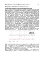
2.3 Filtration, digitization, and multiplexing
Optical signals are subject to several types of noise which must be removed in order to
accurately study the details of the cardiac AP. We will briefly review the types of noise most
relevant to COM systems. Various types of white noise are ubiquitous throughout all types
Photodiodes – Communications, Bio-Sensings, Measurements and High-Energy Physics
144
of electronics, and are typically of frequencies well above those of cardiac signals. Thus low
pass filters are typically used to help remove white noise. Sixty-cyle is another type of noise
that is often encountered when collecting optical signals. This noise may contaminate
signals by way of electromagnetic waves from nearby power outlets, or may be introduced
if equipment used in optical mapping experiments is powered using AC power (i.e., if the
equipment is not isolated). It may be alleviated by the use of a Faraday cage and/or the use
of a band-stop (i.e., notch) filter centered at 60-Hz. Mechanical vibrations may also affect
optical signals, and can range from fluctuations in air current to vibrations due to foot
traffic. Sources of mechanical vibrations are highly varied in nature, and must be dealt with
on a case-by-case basis. A research-grade optical table with active isolation should be
sufficient to suppress most sources of mechanical noise. Optical recordings may also contain
drifts in basline voltage due to several sources. These include photobleaching, dye washout,
and dye internalization into the inner leaflet of the cell membrane. One way to reduce the
impact of these noise sources is to employ the technique of ratiometry (Knisley et al., 2000),
which is discussed in the Pre/Post-Conditioning section which follows.
Many optical devices, including photodiodes and photomultiplier tubes, record analog
signals that must be digitized before being stored on a PC. Digitization equipment must
have sufficient speed and throughput in order to follow the high spatiotemporal resolution
required for optical mapping applications. A review article by Entcheva et al. summarizes
the state of the art in this sub-field of COM (Entcheva & Bien, 2006).
When data is recorded from a two-dimensional grid of sites simultaneously, the most
intuitive storage method is a two-dimensional matrix of values. However, prior to storage
on a PC, this data must be routed from the digitization equipment to the PC. This requires
arranging the data in a sequential fashion, a process known as multiplexing. For a 16x16
element PDA, data for a single millisecond might be arranged from sites 1 to 256 and then
be sequentially sent to the PC for storage. Following this, the data could then be
demultiplexed and arranged as a 2D matrix, a more logical form for creating activation
maps and other graphics to assist with visualization of the data.
2.4 Pre/post-conditioning of optical data
In contrast to electrical signals, optical signals are highly sensitive to heart motion. Various
methods have been developed in order to reduce “motion artifacts” which are often present
in optical signals. These motion artifacts are thought to be the result of a change in the
location of the mapped region on the heart surface, where a fluorescence gradient typically
exists (Himel & Knisley, 2006). Methods to reduce motion artifact include physically
restraining the heart (Efimov et al., 1996; Girouard et al., 1996), the use of electromechanical
uncouplers (Federov et al., 2007; Jalife et al., 1998; Li & Nattel, 2007; Wu et al., 1998), and the
technique of ratiometry (Hooks et al., 2001; Knisley et al., 2000; Kong et al., 2003). Physically
restraining the heart reduces motion artifacts simply by limiting the extent to which the
heart can move during contraction, thus limiting the amount by which the mapped region
moves with respect to its original position on the heart. Electromechanical uncouplers work
by a variety of methods, but most have an effect upon the actin-myosin cytoskeleton which
is responsible for contraction. Electromechanical uncouplers should be used with care, as
some studies have shown that these agents can affect various parameters of the cardiac AP
and may also affect the dynamics of ventricular fibrillation (VF) (Baker et al., 2004; Biermann
et al., 1998; Hyashi et al., 2003; Lee et al., 2001).
The Photodiode Array: A Critical Cornerstone in Cardiac Optical Mapping
145
Ratiometry is a signal processing method that requires the use of two recorded optical
signals, each of a different band of the wavelength spectrum. We will refer to the longer
wavelength signal as “red” and the shorter wavelength signal as “green”. When the V
m
-
sensitive dye di-4-ANEPPS is excited, the peak of the emission spectrum of the dye shifts
toward shorter wavelengths (green). Thus the green signal would show an increase in
fluorescence intensity while the red signal would show a corresponding decrease in
intensity. Using this method, an upright cardiac AP would be recorded in the green signal
while an inverted (or “upside-down”) AP would be recorded in the red signal. The
important thing to consider is that the emission signal corresponding to V
m
is emitted at a
relatively narrow frequency band. Contrastingly, emission due to motion is not heavily
wavelength-dependent, and will cause the change in fluorescence signals in the same
direction regardless of the wavelength band of the collected signal. Since the motion signals
are common to both collected wavelengths, we may reduce motion artifacts by simply
taking the ratio of the green signal to the red on a point-by-point basis. This will cause a
significant reduction in the motion artifact, and will help us to isolate the electrical signal.
This technique could be achieved in the laboratory by using dual PDAs and separating
fluorescence emission into two wavelength bands, one above and one below the peak
emission wavelength of the dye of interest. In addition to motion artifact removal,
ratiometric signals have also been used to study motion artifacts optically. This may be
achieved by subtracting the electrical signal from the signal containing both electrical and
motion components (Himel et al., 2006).
Since fibrillation (both ventricular and atrial) is a topic of great clinical and theoretical interest,
considerable effort has been expended in order to analyze data recorded from the fibrillating
heart. This data is challenging to analyze and interpret, since recordings of fibrillation often
have a chaotic appearance when viewed with time as the horizontal axis. Thus a variety of
alternate methods have been used to gain insight into the nature of fibrillation, including
dominant frequency analysis (Caldwell et al., 2007; Choi et al., 2003; Choi et al., 2006; Joel &
Hsia, 2005; Moreno et al., 2005; Wu et al., 2004; Wu et al., 2006; Zaitsev et al., 2003) and mutual
information (Omichi et al., 2004, Wu et al., 2005). More recently the use of a metric known as
spatiotemporal entropy has been used to analyze oscillatory dynamics in cardiac and neural
systems (Bub et al., 2005; Jung et al., 2000; Himel et al., 2009).
Dominant frequency analysis involves use of the Fourier transform to examine the frequency
content of fibrillation recordings. Some groups have used dominant frequency analysis to
support the theory of a “mother rotor” (i.e., a high-frequency region of the heart that drives
fibrillatory activity) (Chen et al., 2000; Jalife et al., 1998; Zaitsev et al., 2000), however this issue
remains controversial (Berenfeld et al., 2001). Others believe that fibrillation is maintained by
the constant creation and annihilation of wavelets which occur due to functional and
anatomical heterogeneities (Choi et al., 2002; Lee et al., 1996; Moe, 1962; Rogers et al., 1999;
Valderrábano et al., 2002). More recently, some groups have concluded that fibrillatory activity
may be driven by both mechanisms, depending on specific conditions in the heart (Chen et al.,
2003; Liu et al., 2004; Nash et al., 2006; Wu et al., 2002).
Mutual information techniques have been used to examine the relationship between V
m
and
Ca
i
. Algorithms assign a numerical value for individual signals in order to quantify the
degree of similarity between V
m
and Ca
i
during fibrillation in order to give insight into the
mechanisms of arrhythmogenesis and the maintenance of fibrillation; however, mutual
information must be calculated for individual signal pairs and by itself does not indicate
spatiotemporal heterogeneities in V
m
/Ca
i
relationships.
Photodiodes – Communications, Bio-Sensings, Measurements and High-Energy Physics
146
Spatiotemporal entropy has been used to quantify the degree of uncertainty in both time
and space by considering them as lumped parameters, and analyzing activations in the
context of space-time cubes (i.e., stacked two-dimensional optical maps with time as the
third dimension). Spatiotemporal entropy has been used to analyze neural simulations as
well as oscillatory dynamics in cultured cell monolayers (Bub et al., 2005; Jung et al., 2000).
Spatiotemporal entropy analysis is appealing when analyzing optical mapping data, since
one of the main strengths of COM data lies in its spatial resolution.
3. Studies in cardiac electrophysiology research using photodiode arrays
This section will showcase three recent optical mapping studies from this lab which examine
cardiac arrhythmia mechanisms in the context of global ischemia (Himel et al., 2009;
Lakireddy et al., 2005; Lakireddy et al., 2006). These studies examine the dynamic
relationship between V
m
and Ca
i
over the course of ischemia/reperfusion injury. These
studies used a photodiode-based system which simultaneously records V
m
and Ca
i
with two
separate 16x16 PDAs (figure 2 shows 16x16 element photoactive region of the PDA, see
figure 3 for a schematic of the simultaneous dual-measurement system). This system was
designed by B.R. Choi and G. Salama, and uses two Hamamatsu C4675-103 detectors. Please
see the excellent review by Salama et al. for more details regarding this system (Salama et
al., 2009). The whole-heart guinea pig (GP) Langendorff model was used, where the aorta
was cannulated and hung vertically within a surrounding bath of physiological solution
referred to as Tyrode’s solution. Heated (~37° C), oxygenated Tyrode’s solution was
pumped retrogradely through the aorta in order to nourish and oxygenate the heart via the
coronary arteries. These studies simulated the condition of global ischemia (i.e., oxygen
deprivation) and reperfusion by temporarily interrupting perfusion into the coronary
arteries and then restarting the perfusion. The guinea pig animal model is similar to human
physiology in terms of its AP morphology and intracellular calcium handling.
Study 1 (Himel et al., 2009): Ventricular tachycardia is frequently observed in the clinical
environment. VT may either be brief (<30 seconds) or may continue indefinitely, and patient
survival is critically dependent on the duration of the VT episode. Spontaneous termination
of the VT episode within a few seconds leaves the patient unharmed. If the VT episode
continues however, the patient is typically dependent upon a defibrillatory shock to
terminate the episode, without which the patient may not survive. Although extremely
important clinically, the mechanism which determines the duration of the VT episode is not
well understood. It is thought that uncoupling between V
m
and Ca
i
coupling may play a role
in determining whether an episode of VT will terminate spontaneously or continue
indefinitely. This study sought to use the concept of spatiotemporal entropy (E) as a metric
to determine the degree of uncoupling between V
m
and Ca
i
during the early phases of a VT
episode, and to test the predictive power of E for VT duration. During normal sinus rhythm,
propagation of excitation waves in the heart is uniform and wavebreak is typically not
observed. During episodes of VT, wavebreak is common, and fragmentation of excitation
waves in the heart is frequently observed. Moreover, differences between V
m
and Ca
i
signals
are often observed. These differences in V
m
/Ca
i
coupling may be quantified using the
absolute value of the difference in E, symbolized by E
d
.
This study examined several groups of VT episodes which were divided according to
whether or not they terminated spontaneously. Self-terminating episodes of VT were further
classified as short (<5 seconds) or long (>5 seconds). E
d
was determined for the first 500 ms
The Photodiode Array: A Critical Cornerstone in Cardiac Optical Mapping
147
of all VT episodes. E
d
values for non self-terminating episodes of VT were significantly
greater than self-terminating VT episodes. Further, E
d
values for long self-terminating
episodes of VT were significantly greater than those for short self-terminating episodes.
Fig. 3. Optical mapping diagram for simultaneous V
m
and Ca
i
measurements. For panel A),
the position of each filter is indicated by thin curved lines with arrowheads, and the
characteristics of the filters are underlined (high pass filters are indicated by a single
number, whereas band pass filters have number ± band). The calcium and voltage PDAs are
shaded gray. The large color-filled lines indicate the path of the given color of light. The
excitation source is the bottom component in panel A). Panel B) shows an map of optical
signals, and panel C) shows enlarged traces of the indicated pixels. The blue signal in panel
C) represents V
m
, whereas the red signal indicates Ca
i
.
Photodiodes – Communications, Bio-Sensings, Measurements and High-Energy Physics
148
Wavebreak and differences in V
m
and Ca
i
spatial fluorescence maps were consistently
identified during periods of high E and high E
d
. The results are illustrated by figures 4 and
5, which show typical examples of low and high E
d
during VT episodes.
High E
d
correlated with a greater duration of a VT episode. This may be related to
destabilization of propagation and uncoupling between V
m
and Ca
i
activation wavefronts.
Study 2 (Lakireddy et al., 2005): This study examines spatial dispersion of repolarization in
the context of global ischemia, and also the role spatial dispersion plays in the development
of electrical alternans. Electrical alternans is a term used to describe beat-to-beat alterations
in AP morphology. For example, a one-to-one APD alternans occurs when a normal AP is
followed by a short-duration AP, which is then followed by normal AP, short-duration AP,
and so on. Electrical alternans are considered to be a strong marker of electrical instability,
and often precede malignant arrhythmias such as ventricular tachycardia (VT) and VF
(Hohnsloser et al., 1998; Gold et al., 2000; Ikeda et al., 2006; Pastore et al., 1999; Pham et al.,
2003; Rashba et al., 2004; Rosenbaum et al., 1994).
In this study by Lakireddy et al., ischemia-induced changes in APD and intracellular
calcium transient duration (Ca
i
T-D) were determined, and their relationship with electrical
alternans was investigated. Recordings show that ischemia resulted in a significant decrease
in APD, but resulted in a significant increase in Ca
i
T-D. In addition, changes in APD were
spatially heterogeneous while changes in Ca
i
T-D were relatively homogeneous (see figure
6). Sites with less shortening of APD displayed alternans in both Ca
i
T-D and APD, while
sites with more shortening of APD displayed Ca
i
T-D alternans but little or no APD
alternans, leading to a condition of significant spatial dispersion of the APD. The condition
of increased spatial dispersion due to ischemia is thought to account for the vulnerability of
the heart to alternans.
Study 3 (Lakireddy et al., 2006): In a second study by Lakireddy et al., the association
between arrhythmogenesis and spontaneous calcium oscillations (S-CaOs) was examined in
the intact heart. It is known that ischemia/reperfusion leads to elevated Ca
i
and an
alteration in Ca
i
kinetics (Bers, 2002; Marban et al., 1990; Steenbergen et al., 1987). This
alteration in normal Ca
i
kinetics can lead to S-CaOs. Under such conditions, the normal
master/slave relationship between V
m
/Ca
i
T signals is reversed (i.e., calcium signals precede
and drive V
m
).
The goal of this study was to investigate the correlation between S-CaOs and
arrhthmogenesis using an experimental GP model with 15 minutes of no flow ischemia
followed by 15 minutes of reperfusion. Changes in Ca
i
and Vm in a limited zone of the
epicardial surface of the GP heart were simultaneously recorded and carefully examined.
The study provided evidence of a linkage between S-CaOs and arrhythmogenesis in the
setting of ischemia/reperfusion (I/R). In the intact heart during I/R, spontaneous
premature beats (PBs) occurred and were ubiquitous. Some PBs initiated a VT or VF (see
figure 7), while others remained confined to their site of origin and did not result in an
arrhythmia (see figure 8). Two important observations had to be made in order to link an
arrhythmia to S-CaOs in the experimental model. First, the beginning of S-CaOs preceded
the onset of the simultaneously recorded membrane depolarization by 2-15 ms at a very
restricted site in the optical field. In recordings obtained further away from the focal site of
origin, the relative amplitude of the S-CaOs gradually decreased and the start of membrane
depolarization preceded the onset of S-CaOs. Second, the presence of some degree of
conduction block, which by definition is the failure of S-CaOs to trigger a fully propagated
The Photodiode Array: A Critical Cornerstone in Cardiac Optical Mapping
149
response, was essential for the localization of the focal site of origin. Thus S-CaOs may
remain concealed (and hence benign) or may manifest as PBs, VT or VF.
Fig. 4. Example of spatiotemporal entropy from a short self-terminating run of a ventricular
tachyarrhythmia. V
m
and Ca
i
were recorded using a dual PDA system. Entropy traces (2nd
row, panel A) show small differences between V
m
and Ca
i
entropy, indicating a low degree
of spatiotemporal uncoupling. Fluorescence maps in panel B show similar, but not identical
excitation wavefronts for V
m
and Ca
i
. Values given for traces and fluorescence maps are
given in ms. (reproduced with permission from Himel et al., 2009).
Photodiodes – Communications, Bio-Sensings, Measurements and High-Energy Physics
150
Fig. 5. Example of spatiotemporal entropy from a non self-terminating run of a ventricular
tachyarrhythmia. Differences in the entropy traces (2nd row, panel A) show a disparity
between V
m
and Ca
i
entropy and spatiotemporal uncoupling. Spatial fluorescence maps
reflect the disparity shown by the V
m
and Ca
i
traces. Values given for traces and
fluorescence maps are in ms. (reproduced with permission from Himel et al., 2009).
4. Recent advances in cardiac optical mapping
We will now turn to briefly discuss a few of the important recent advances in COM.
Optrodes are bundles of microscopic fiberoptic cables which are inserted into cardiac tissue
in order to interrogate intramural activation patterns. They are similar to plunge needle
electrodes in their usage; however optrodes are capable of measuring complete APs,
including the repolarization phase, whereas plunge electrodes measure extracellular
potentials only. It is thought that in the future optrodes will play an important role in more
carefully examining transmural dispersion of repolarization, an important factor in
arrhythmogenesis in a variety of cardiac diseases (Antzelevitch, 2007; El-Sherif et al., 1996;
Milberg et al., 2005; Shimizu et al., 1997). Optrodes may also be important in the study of the
dynamics of arrhythmic circuits, since they are often present deeper in the myocardial wall
(Allison et al., 2007; Li et al., 2008; Valderrábano et al., 2001). However, like plunge
electrodes optrodes must also be inserted into the tissue and therefore cause damage which
may by itself alter activation patterns. Thus the effects of this insertion must be carefully