Fundamental and Advanced Topics in Wind Power Part 9 pptx
Bạn đang xem bản rút gọn của tài liệu. Xem và tải ngay bản đầy đủ của tài liệu tại đây (1.21 MB, 30 trang )
Monitoring and Damage Detection in Structural Parts of Wind Turbines 23
limitation lies in the fact that future research will be strongly connected to full scale tests and
that such tests cannot be carried out by research organisations alone.
Considered as a whole, these results suggest that there are monitoring methods that can
be applied to wind turbines and thereby contribute to making the process of harvesting
renewable energy more reliable.
This research will serve as a base for future studies on the topic of combining the different
classes of methods to develop a monitoring system that is able to predict the residual life-time
of structures. Such systems are of great use for off-shore wind turbines, because they are the
basis of a maintenance on demand.
6. Acknowledgements
Parts of the present and still ongoing research in this field as well as the publication of this
chapter are funded by the German federal state of Hesse (project „LOEWE-Zentrum AdRIA:
Adaptronik Research, Innovation, Application“, grant number IIIL4-518/14.004 (2008))
as well as in the framework of the programme „Hessen ModellProjekte“ (HA-Projekt-Nr.:
214/09-44). This financial support is gratefully acknowledged.
7. References
Andersen, P. (1997). Identification of Civil Engineering Structures using Vector ARMA models,
PhD-Thesis, University of Aalborg, Aalborg.
Andersen, P. & Brincker, R. (2000). The Stochastic Subspace Identification Techniques,
www.svibs.com.
Andersen, P., Brincker, R., Goursat, M. & Mevel, L. (2007). Automated Modal Parameter
Estimation For Operational Modal Analysis of Large Systems, Proceedings of the
2nd International Operational Modal Analysis Conference, ed. Brincker R. & Møller N.,
Copenhagen, pp. 299–308.
Asmussen, J. C. (1998). Modal Analysis Based on the Random Decrement Technique, Application to
Civil Engineering Structures, PhD-Thesis, University of Aalborg, Aalborg.
Ballah, S. & Soh, C. K. (2003). Structural impedance based diagnosis by piezo-transducers.
Earthquake Engineering and Structural Dynamics, No. 32, pp. 1897-1916.
Bartel, T., Atzrodt, H., Herold, S. & Melz, T. (2010). Modelling of an Active Mounted Plate
by means of the Superposition of a Rigid Body and an Elastic Model, Proceedings of
ISMA2010. International Conference on Noise and Vibration Engineering, pp. 511-523.
Bendat, J. S. & Piersol, A. G. (2000). Random Data: Analysis and Measurement Procedures, John
Wiley & Sons, New York.
Bodeux, J. B. & Colinval, J. C. (2001). Application of ARMAV models to the identification and
damage detection of mechanical and civil engineering structures. Smart Materials and
Structures, Vol. 10, pp. 479-489.
Boller, C. & Buderath, M. (2006). Fatigue in aerostructures – where structural health
monitoirng can contribute to a complex subject. Phil. Trans. R. Soc. A, No. 365, Dec
2006.
Brincker, R., Krenk, S. & Jensen, J. L. (1991). Estimation Of Correlation Functions By The
Random Decrement, Proceedings of The Florence Modal Analysis Conference, Florence,
pp. 783–788.
229
Monitoring and Damage Detection in Structural Parts of Wind Turbines
24 Will-be-set-by-IN-TECH
Brincker, R., Zhang, L. & Andersen, P. (2000). Modal Identification from Ambient Response
using Frequency Domain Decomposition, Proceedings of the 18th IMAC, San Antonio,
TX, USA, pp. 625–630.
Buff, H., Friedmann, A., Koch, M., Bartel, T. & Kauba, M. (2011). Systematic preparation
of Random Decrement Method based Structural Health Monitoring, Proceedings of
the ICEDyn, International Conference on Structural Engineering Dynamics, Tavira, 2011.
Accepted for presentation.
Carden, E. P. & Fanning, P.(2004). Vibration Based Condition Monitoring: A Review. Structural
Health Monitoring, Vol. 3
(4), pp. 355–377.
Chesné, S.& Deraemaeker, A. (2010). Sur l’utilisation des transmissibilités pour la localisation
des défauts dans les systèmes non dispersifs. 10ème Congrès Francais d’Acoustique,
Lyon.
Ciang, C. C., Lee, J R. & Bang, H J. (2008). Structural health monitoring for a wind turbine
system: a review of damage detection methods. Measurement Science and Technology,
No. 19, DOI: 10.1088/0957-0233/19/12/122001.
Cole, H. (1973). On-line failure detection and damping measurement of aerospace structures by
random decrement signatures, Report NASA CR-2205.
DIN 45 667 (1969). Klassierverfahren für das Erfassen regelloser Schwingungen, Beuth-Vertrieb.
DIN 50 100 (1978). Dauerschwingversuch – Begriffe, Zeichen, Durchführung, Auswertung,
Beuth-Vertrieb.
Ewins, D. J. (2000). Modal Testing: Theory, Practice and Application, Research Studies Press, Ltd.,
Baldock.
Fan, W. & Qiao, P. (2010). Vibration-based Damage Identification Methods: A Review and
Comparative Study, Structural Health Monitoring, Vol. 10(1), pp. 83-111.
Farrar, C. R. & Doebling, S. W. (1997). An Overview of Modal-Based Damage Identification
Methods. EUROMECH 365 International Workshop: DAMAS 97, Structural Damage
Assessment Using Advanced Signal Processing Procedures.
Friedmann, A., Koch, M. & Mayer, D. (2010). Using the Random Decrement Method for
the Decentralized Acquisition of Modal Data, Proceedings of ISMA2010. International
Conference on Noise and Vibration Engineering, Leuven, September 2010, pp. 3275-3286.
Fritzen, C. P., Kraemer, P. & Klinkov, M. (2008). Structural Health Monitoring of Offshore Wind
Energy Plants, Proc. 4th Europ. Workshop on Structural Health Monitoring, Krakow,
Poland, pp.3-20.
Giurgiutiu, V.& Cuc, A. (2005). Embedded Non-destructive Evaluation for Structural Health
Monitoring, Damage Detection, and Failur Prevention. The Shock and vibration Digest,
Vol. 37(2), pp. 83-105.
Giurgiutiu, V. (2008). Structural Health Monitoring with Piezoelectric Wafer Active Sensors.
Elsevier, Amsterdam, ISBN: 978-0-12-088760-6.
Haibach, E. (1971). Probleme der Betriebsfestigkeit von metallischen Konstruktionsteilen.
VDI-Berichte Nr. 155, pp. 51-57.
Haibach, E. (2006). Betriebsfestigkeit – Verfahren und Daten zur Bauteilberechnung,
Springer-Verlag, ISBN-10 3-540-29363-9, Berlin, Heidelberg.
Hameed, Z., Hong, Y. S., Cho, Y. M., Ahn, S. H. & Song, C. K. (2007). Condition monitoring
and fault detection of wind turbines and related algorithms: A review, Renewable and
Sustainable Energy Reviews, Vol. 13, pp. 1–39.
230
Fundamental and Advanced Topics in Wind Power
Monitoring and Damage Detection in Structural Parts of Wind Turbines 25
Have, A. A. ten (1992) Wisper and Wisperx – Final definition of two standardised fatigue loading
sequencesa for wind turbine blades, National Aerospace Laboratory NLR, Amsterdam,
Netherlands, NLR TP 91476 U.
Herold, S. (2003). Simulation des dynamischen und akustischen Verhaltens aktiver Systeme im
Zeitbereich, Dissertation, TU Darmstadt, 2003.
Herlufsen, H., Gade, S. & Møller, N. (2005). Identification Techniques for Operational Modal
Analysis – An Overview and Practical Experiences, Proceedings of the 1st International
Operational Modal Analysis Conference, Copenhagen.
Heuler, P. & Klätschke, H. (2004). Generation and use of standardized load spectra and
load-time histories. International Journal of Fatigue, No. 27, pp. 974-990.
Humar, J., Bagchi, A. & Xu, H. (2006). Performance of Vibration-based Techniques for
the Identification of Structural Damage. Structural Health Monitoring, Vol. 5
(3), pp.
215–241.
Kammer, D. C. (1991). Sensor Placement on-orbit modal identification and correlation of large
structures, Journal of Guidance, Control and Dynamics 14 (1991), pp. 251-259.
Kessler, S. S., Spearing, S. M. & Soutis, C. (2002). Damage detection in composite materials
using Lamb waves methods. Smart Materials and Structures 11, pp. 269-278.
Kuo, S. M. & Morgan, D. R. (1996). Active Noise Control Systems: Algorithms and DSP
Implementations, John Wiley & Sons, New York.
Lading, L., McGugan, M., Sendrup, P., Rheinländer, J. & Rusborg, J. (2002). Fundamentals for
Remote Structural Health Monitoring of Wind Turbine Blades-aPreproject, Annex
B - Sensors and Non-Destructive Testing Methods for Damage Detection in Wind
Turbine Blades. Risø National Laboratory, Roskilde, Denmark, Risø-R-1341(EN).
Lee, U. & Shin, J. (2001). A frequency response function-based structural damage identification
method. Computers and Structures, Vol. 80, pp. 117–132.
Liang, C., Sun, F. P. & Rogers, C. A. (1994). Coupled Electro-Mechanical Analysis of Adaptive
Material Systems – Deteremination of the Actuator Power Consumption and System
Energy Transfer. Journal of Intelligent Materials and Structures, Vol. 5, pp. 12-20.
Lilov, M., Kauba, M. & Mayer, D. (2010) Structural monitoring and damage detection on CFRP
specimens by using broadband acousto ultrasonic and electromechanical impedance
measures, Proc. 5th Europ. Workshop on Structural Health Monitoring, Sorrento, Italy, p.
G28.
Lunze, J. (2010). Regelungstechnik 1, Springer-Verlag, ISBN 978-3-642-13807-2, Berlin,
Heidelberg.
Lynch, J., Wang, Y., Kenneth, J. L. , Yi, J. H. & Yun, C B. (2006). Performance Monitoring of
the Geumdang Bridge using a Dense Network of High-Resolution Wireless Sensors,
Smart Materials and Structures Vol. 15(6), pp. 1561–1575.
McConnell, K. G. (1995). Vibration Testing – Theory and Practice, John Wiley & Sons, Inc., New
York.
Montalvão, D., Maia, N. M. M. & Ribeiro, A. M. R. (2006). A Review of Vibration-based
Structural Health Monitoring with Special Emphasis on Composite Materials. The
Shock and Vibration Digest, Vol. 38, No. 4, pp. 295-324.
Park, G., Sohn, H., Farrar, C. R. & Inman, D. J. (2003). Overview of Piezoelectric
Impedance-Based Health Monitoring and Path Forward. The Shock and Vibration
Digest, Vol. 35(6), pp. 451-463.
231
Monitoring and Damage Detection in Structural Parts of Wind Turbines
26 Will-be-set-by-IN-TECH
Peeters, B., van der Auweraer, H. & Deblauwe, F. (2006). 10 Years Of Industrial Operational
Modal Analysis: Evolution In Technology And Applications, Proceedings of the
IOMAC Workshop 2006.
Radaj, D. (2003). Ermüdungsfestigkeit - Grundlagen für Leichtbau, Maschinen- und Stahlbau,
Springer-Verlag, ISBN 3-540-44063-1, Berlin, Heidelberg.
Rodrigues, J. & Brincker, R. (2005). Application of the Random Decrement Technique in
Operational Modal Analysis, Proceedings of the 1st International Operational Modal
Analysis Conference, ed. Brincker, R. & Møller, N., Copenhagen, pp. 191-200.
Rytter, A. (1993). Vibration based inspection of civil engineering structures, PhD-Thesis,
Department of Building Technology and Structural Engineering, University of
Aalborg, Aalborg.
Schütz, W., Klätschke, H., Hück, M. & Sonsino, C. M. (1989). Standardised Load Sequences for
Offshore Structures – WASH I. Fatigue Fract. Engng. Struct., Vol. 13(1), pp. 15-29.
Siebel, T. & Mayer, D. (2011). Damage Detection on a Truss Structure using Transmissibility
Functions, Eurodyn 2011, Leuven, Belgium. Accepted for presentation.
Silva, C., Rocha, B. & Suleman, A. (2010). Guided Lamb Waves Based Structural Health
Monitoring Through a PZT Network System. 2nd International Symposium on NDT
in Aerospace 2010 - We.1.B.4.
Sohn, H., Farrar, C. R., Hemez, F. M., Shunk, D. D., Stinemates, D. W., Nadler, B. R. &
Czarnecki, J. J. (2004). A Review of Structural Health Monitoring Literature: 1996 – 2001,
Los Alamos National Laboratory, Report No. LA
−13976 − MS.
Sonsino, C. M. (2004). Principles of Variable Amplitude Fatigue Design and Testing. Journal of
ASTM International, Vol. 1, No. 9, Paper ID JAI19018.
Sonsino, C. M. (2005). Dauerfestigkeit – Eine Fiktion. Konstruktion, No. 4, pp. 87-92, ISSN:
0373-3300.
Uhl, T. (2007). The inverse identification problem and its technical application. Archive of
Applied Mechanics, No. 77, 2007, pp. 325-337.
Westermann-Friedrich, A. & Zenner, H. (1988). Zählverfahren zur Bildung von Kollektiven aus
Zeitfunktionen – Vergleich der verschiedenen Verfahren und Beispiele, FVA-Merkblatt Nr.
0/14, Forschungsvereinigung Antriebstechnik e.V
Viberg, M. (1995). Subspace-based Methods for the Identification of Linear Time-invariant
Systems. Automatica, Vol. 31(12), pp. 1835-1851.
Zagrai, A. N. & Giurgiutiu, V. (2002). Electro-Mechanical Impedance Method for Crack
Detection in Thin Plates. Journal of Intelligent Material Systems and Structures, Vol. 12,
pp. 709-718.
Zhang, L. (2004). An Overview of Major Developments and Issues in Modal Identification.
Proc. IMAC XXII, Detroit.
Zhang, L., Brincker, R. & Andersen, P. (2005). An Overview of Operational Modal Analysis:
Major Development and Issues, Proceedings of the 1st International Operational Modal
Analysis Conference, Copenhagen.
Zimmerman, A. T., Shiraishi, M., Swartz, R. A. & Lynch, J. P. (2008). Automated Modal
Parameter Estimation by Parallel Processing within Wireless Monitoring Systems,
Journal of Infrastructure Systems Vol. 14(1), pp. 102-113.
232
Fundamental and Advanced Topics in Wind Power
10
Magnetic Suspension and
Self-pitch for Vertical-axis
Wind Turbines
Liu Shuqin
School of Electrical Engineering,
Shandong University,
China
1. Introduction
Energy is important for the development of human civilization. As conventional energy
exhausts, the development of clean and renewable energy, such as wind and solar becomes
ever important to people’s live. The wind power has been harnessed by mankind for a long
time and the associated technology is more advanced than other clean energies. Nowadays
wind power increasingly attracts interests and its utilization has entered a rapid
development stage.
There are two types of wind turbines, namely horizontal-axis wind turbine (HAWT) and
vertical-axis wind turbine (VAWT). The latter has many advantages, such as low cost,
simple-structured blades, convenient installation and maintenance, and the ability to utilize
wind from all directions without the need of a steering mechanism. A special VAWT
implemented with magnetic suspension and self-pitch blade design will be introduced in
this chapter. It not only has the advantages of traditional VAWT, but also the advantages of
low threshold starting wind-speed, high wind power efficiency, etc.
Discussion in this chapter includes the benefits of applying magnetic bearing technology to
the wind turbine. Specifically, the entire wind turbine rotor weight can be supported by
magnetic bearings. The friction of the bearings is essentially non-existence. There is no need
for bearing lubrication, and the maintenance cost can be reduced. Furthermore, the magnetic
suspension technology can eliminate mechanical vibration and reduce noise. Since low
friction also reduces starting torque, the magnetic bearings enable producing power at lower
wind speed than conventional bearings.
The discussion also includes a blade-pitch adjusting technique. Conventional VAWT applies
special blade adjusting mechanism which is complicated in structure, costly to fabricate and
wastes power. Herein, the blades in a magnetic suspended VAWT are designed to adjust the
pitch automatically and do not require any dedicated special devices. The blade pitch is
adjusted naturally during rotation for the best windward angle. As a result the blades
always produce the maximum thrust wind force improving the wind turbine efficiency.
Thus, the magnetically suspended and self-pitched vertical-axis wind turbine will be
designed with uncomplicated structure, high efficiency and low cost.
Fundamental and Advanced Topics in Wind Power
234
2. Vertical-axis wind turbine
2.1 Basic principle of vertical axis-machine
Wind machine is a kind of energy conversion device, which converts wind energy into
mechanical, electric or heat energy. According to their rotor layout, wind turbines can be
categorized into horizontal-axis wind turbines (HAWT) and vertical-axis wind turbines. The
rotor of a HAWT is horizontal and must point to the wind. The rotating plane of HAWT
blades is perpendicular to the wind direction during operation. The turbine blades are radial
and their number is commonly 2~3. The shape of a turbine blade is always similar to a wing.
It is perpendicular to the rotating shaft and there is an angle between the blade and rotating
plane. Since the HAWT works on the principle of airfoil lift, its torque tends to be large and
efficiency high in utilizing wind energy. Yaw device is necessary to turn the blades rotating
plane in line with the wind direction. The HAWTs have been investigated thoroughly in
theory and have the advantages of high wind energy utilization efficiency. They are the
mainstream commercial products of the current wind turbine technology.
The shaft of a VAWT is perpendicular to the ground and the wind direction. VAWT accepts
the wind from all horizontal directions; there is no need of a yaw control devices, making
the structure design simple and reducing precession force on blades. Comparing to HAWT,
a VAWT has the advantages of low noise and less adverse effect on environment.
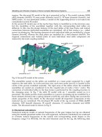
1 nose clip, 2 blade nose, 3 blade support pole, 4 wheel arm, 5 upper cover, 6 baffle, 7 position disk, 8
bearing cover, 9 upper ratchet, 10 lower ratchet, 11 generator support, 12 turbine frame, 13 ventral
shield, 14 support shelf.
Fig. 1. Components of a vertical-axis wind turbine
Magnetic Suspension and Self-pitch for Vertical-axis Wind Turbines
235
There are two kinds of VAWTs. The first kind works on the principle of wind drag. Its
typical structure is the S-type (Savonius) wind turbine, such as the cup-shaped wind wheel
blades for wind-speed measurement. The S-type wind turbine consists of two axis -
staggered half cylinders, and the starting torque is large. Unsymmetrical airflows exist
around the rotor producing the lateral thrust to the turbine blades. The second kind of
VAWT works on the principle of airfoil lift. Its typical application is Darrieus wind turbines.
Darrieus wind turbines have various forms, including H- type and ф-type. An H-type wind
turbine has a simple structure, but centrifugal force may generate serious bending stress on
its turbine wheel connections. The flexural blades in ф-type wind turbine only bear the
tension without centrifugal load; the bending stress in blades of ф-type wind turbine is
therefore mitigated.
The VAWT wheel rotates in a horizontal plane and there is no vertical motion of the
blades. Researchers used to believe that the tip-speed ratio (the ratio of blade tip
rotational speed to wind speed) of VAWT cannot be greater than 1, and therefore the
associated wind energy efficiency is lower than that of a HAWT. The VAWT blades were
designed by using blade element momentum method. But the airflow through a VAWT,
typically separated unstable flows, is more complicated than those of HAWT. The blades
elements moment theory is not suitable for its analysis and design, and this is one reason
for less development in VAWT. But as technology progressing, researchers have realized
that only S-type VAWTs are limited by the tip-speed ratio less than 1. For the lift-type
wind wheel (Darrieus-type) the tip-speed ratio can reach as high as 6. Therefore, its wind
energy utilization efficiency is not lower than HAWT. Recognizing the advantage, many
institutions have started investigation on VAWTs and achieved considerable
advancement in recent years.
2.2 Different vertical axis wind turbines
As the wind power technology develops, the unique advantages of VAWTs have been
unveiled and appreciated, especially for those small wind turbine applications. The recent
progress in VAWT research has enabled many commercializations of small VAWTs as
follows.
2.2.1 Sail S-type roof VAWT
Figure 2 shows the VAWT manufactured by Enviro-Energies Holdings, a Canadian
company. The main line of its production is a 10KW wind turbine, with advantages of low-
speed, high power output, quiet operation, and maintenance free. It can be installed on roof
for domestic power need.
2.2.2 Light type VAWT
As shown in Figure 3, Urban Green Energy (
products/uge-4k) has developed and patented a revolutionary new dual axis design that
eliminates the main concern of other vertical axis wind turbines that is premature bearing
failure. Its vertical axis machines include those rated for 600W, 1KW and 4KW. They can be
installed on top of a tower, roof and other suitable places. These wind turbines can be
connected to utility grid. They are made of glass or carbon fibers. The 4KW model weighs
about 461Kg, cuts in wind speed at 3.5m/s and is rated at wind speed 12m/s.
Fundamental and Advanced Topics in Wind Power
236
Fig. 2. VAWT made by Enviro-Energies and installed on the company’s roof
Fig. 3. VAWT made by Urban Green Energy
Magnetic Suspension and Self-pitch for Vertical-axis Wind Turbines
237
2.2.3 H type VAWT
Figure 4 shows a small VAWT developed by Ropatec of Italy. The Ropatec products are sold
to more than thirty countries worldwide, supplying reliable electrical power for families,
farms, remote pastoral areas, communications companies and enterprise groups. Its VAWTs
have four ratings, i.e., 1KW, 3KW, 6KW and 20KW. The 20KW wind turbine has 5 blades;
the others have 3 blades.
Fig. 4. H-type VAWT made by Ropatec of Italy
Fig. 5. Aesthetic VAWT made by Oy Windside in Finland
Fundamental and Advanced Topics in Wind Power
238
2.2.4 Aesthetic VAWT
A new type of VAWT as shown in Figure 5 has been developed by Oy Windside in Finland.
The wind turbine as a derivative of marine engineering, can be used for charging batteries
and provide an environment-friendly image. One of the applications of Oy Windside wind
turbines is about “wind art”. The concept is to integrate the wind turbine into art and
provide lighting. The aesthetics function and ecological concept are both considered in the
turbine design.
2.2.5 Drag-type and lift-type combined VAWT
Figure 6 shows the VAWT produced by Green Giant Tech, Taiwan. Green Giant Tech has
combined the benefits of the Savonius-type blade and the Darrieus-type blade, applying
both the drag and lift forces of wind power. Its VAWT includes three models rated at 400W,
3.6KW and 5KW. It also manufactures street lighting devices for wind and solar power.
Fig. 6. VAWT made by Green Giant Tech's in Taiwan
2.3 Magnetic suspension and self-pitch for vertical axis wind turbine
Maglev Engineering Research Center, Shandong University, China has committed to the
magnetic bearing research and related product development. Recently, magnetic suspension
technology has been applied to the vertical axis wind turbine, in which the entire rotor
weight of a VAWT was suspended by magnetic bearing. The turbine friction was greatly
reduced, and start-up wind speed decreased. Figure 7 shows the magnetically suspended
and self-pitched VAWT for street lighting.
Since the self-pitch technique and magnetic suspension were applied to the Shandong
University VAWT, the wind power efficiency and system performance of the wind turbine
have been greatly improved. The manufacturing cost and operational cost were also
effectively reduced. This new magnetically suspended vertical-axis wind generator has
irreplaceable advantages compared with other VAWTs in the market. Due to its low cost
and suitability for high-power single devices, this new VAWT design will have broad
commercial potential.
Magnetic Suspension and Self-pitch for Vertical-axis Wind Turbines
239
Fig. 7. Magnetically suspended and self-pitched VAWT from Maglev Engineering Center,
Shandong University
3. Application of magnetic suspension in wind turbine
3.1 Principle and types of magnetic suspension
Magnetic suspension means that an object is suspended by magnetic attraction and/or
repulsion forces to achieve non-contact support and low-friction in motion. The magnetic
suspension as a branch in mechatronics technology, involves disciplines in
electromagnetism, power electronics, signal processing, control engineering, statics and
dynamics. Therefore, the development of the magnetic suspension technology has been
closely related to and relied on the development of these fields of disciplines.
Because of no mechanical contact in the magnetic bearing, it has many advantages,
including no wear, no contamination, suitable for long-term use in vacuum and corrosive
environment, no mechanical friction, low noise, low power loss and no need of lubrication
or sealing. Therefore, magnetic suspension technology can be used for high-speed
applications to eliminate mechanical problems related to lubrication and power loss.
There are many applications of the magnetic suspension technology, including maglev train
and magnetic bearing. Many countries have developed different types of maglev trains;
Germany, Japan and China are among those having the most mature maglev technology.
The fastest speed of the maglev train can reach 500km/h. On the other hand, the magnetic
bearing technology has been widely applied in the aerospace industry, medical health field
and new energy power. Some magnetic bearings have been tested in space shuttles and
rockets in USA and Japan and achieved satisfactory performances. There were magnetic
bearings successfully implemented in artificial heart pump developed by University of
Virginia and University of Utah.
Base on the source of the magnetic field, magnetic bearings can be classified into three kinds
as follows:
1. Active Magnetic Bearing (AMB) - The magnetic field is controllable. The control system
detects the position of the rotor and actively controls the suspension of the rotor. The
bearing stiffness and damping are electronically tuneable and the load capacity is large.
Fundamental and Advanced Topics in Wind Power
240
The principle of active magnetic suspension is depicted by a simple magnetic
suspension system in Figure 8, which shows a displacement sensor, controller and
actuator. The actuator includes electromagnets and power amplifiers. Assuming there is
a downward perturbation, the position change of the suspended object, such as the
rotor in Figure 8, can be detected by the sensor and the displacement signal
immediately is transmitted to the controller. The signal will be transformed into a
command by the microprocessor of the controller, which in turn produces a change or
increase of control current in the electromagnets. The suspended object will be then
pulled back up to its original position by the changing magnetic field generated in the
electromagnet. Therefore, the rotor will always be kept at a preset position regardless
the perturbation is down or up.
Fig. 8. Diagram of active magnetic suspension system
2. Passive Magnetic Bearing (PMB) - As showed in Figure 9, the PMB magnetic field is
created using permanent magnets or superconductors. The rotor is suspended by
passive magnetic forces. The advantages of PMB are its simple structure, low cost, low
power loss, etc., but the load capacity of PMB is small and so is the stiffness.
Fig. 9. Permanent magnetic bearings
3. Hybrid magnetic bearing (HMB) - As showed in figure 10, the mechanical structure of
HMB includes electromagnet and permanent magnet (or superconductor); the magnetic
force is generated by both the permanent magnet and electromagnet. Its structure
complexity, cost and performance are average between AMB and PMB.
Magnetic Suspension and Self-pitch for Vertical-axis Wind Turbines
241
i
i
a
a
b
b
N
S
S
N
1 rotor, 2 permanent magnets, 3 stator, 4 electromagnet coils.
Fig. 10. Hybrid magnetic bearing
Based on the functions of magnet bearings, magnetic bearing can be further classified as
axial (thrust) magnetic bearing and radial magnetic bearing.
3.2 Magnetic suspension technology in wind turbine
Permanent magnet bearing has the advantages of low power consumption, no mechanical
contact and suitable for severe adverse environment. In recent years, with the rapid
development of permanent magnet material, the technology of permanent magnetic
suspension has been expanded to wind turbine applications. This has greatly reduced the
cost and stringency of wind power. Specifically, the application of magnetic suspension to
wind turbines has achieved the following advantages:
1. Starting wind speed is reduced by magnetic suspension due to reduced bearing friction
and power output of wind turbine is increased for the same wind speed.
2. Magnetic suspension has largely changed the traditional wind turbine rotor system
design using special rolling-element or oil-film bearings. These traditional bearings
depend on careful lubrication and sealing for long service life, impact resistance, and
high reliability. The magnetic suspension not only reduces the cost of the bearings and
their maintenance, but also reduces the downtime of the wind turbine and therefore,
improves the over-all efficiency of the system.
Magnetic suspension technology applied to wind turbine is an emerging technology; the
development of maglev magnetic wind turbine is just beginning. Although there claimed
many maglev wind turbine products have been developed, relevant published studies are
rare.
Currently, the studies on magnetic suspension of wind turbines have been focused on the
HAWTs. A typical magnetic suspension for an HAWT is to use PMB in radial directions and
a mechanical bearing or a ball in axial direction.
Figure 11 shows a magnetic suspension system of wind turbine with five degrees of
freedom using radial and axial magnetic bearings.
Fundamental and Advanced Topics in Wind Power
242
1 lower backup thrust ring, 2 axial magnetic bearing, 3 radial magnetic bearing, 4 generator, 5 upper
backup bearing, 6 lower backup bearing, 7 rotor shaft, 8 radial magnetic bearing stator, 9 shell, 10 upper
backup thrust ring, 11 axial magnetic bearing rotor disk, 12 axial magnetic bearing stator, 13 radial
magnetic bearing rotor, 14 generator rotor, 15 generator stator
Fig. 11. Magnetic suspension system of vertical axis wind turbine
The thrust (axial) bearing is the most important part of the VAWT magnetic suspension
system. It supports the weight of the blades and generator rotor. An implementation of the
thrust bearing using permanent magnets is presented in Figure 12(a). A passive radial
bearing structure resisting radial disturbance is shown in Figure 12(b).
Fig. 12. Axial (a) and radial (b) magnetic bearing in VAWT
PMBs are normally made of NdFeB (neodymium iron boron) magnets. These magnets are
currently the best choice for magnetic bearings because of its high magnetic energy product
and low cost. Also its process-ability is better than other permanent materials, such as SmCo
alloy. But the temperature stability and erosion resistance are needed to improve for NdFeB
magnets. Inferior to SmCo, typical NdFeB Curie temperature is 312°C and reversible
temperature coefficient of remanence is -0.13/°C. Typical NdFeB working temperature is
below 80°C. For better temperature stability and erosion resistance, the NdFeB magnets
chosen for wind turbines have been manufactured by hot-rolling process. The process yields
good tension strength, and oxidation resistance.
Magnetic Suspension and Self-pitch for Vertical-axis Wind Turbines
243
4. Self-pitch technique in wind turbine
Pitch control is one of the key technologies in wind turbine and its development has
progressed from fixed pitch to controllable pitch. The fixed-pitch design has the blades fixed
on the arms so that the windward angle will not change with wind speed in operation. The
controllable pitch design is to change the blade pitch angle according to the wind speed in
order to control the generator output power. Moreover, it is necessary to control blade pitch
to lower starting torque during wind turbine start-ups. Comparing with the fixed-pitch
wind turbines, the controlled-pitch designs can produce more wind power, because it can
vary blade pitch according to variable wind speed.
For stable loading control, security and high efficiency, blade-pitch control is employed in
most large HAWTs. The pitch-controlled system consists of pitch bearing and pitch gear.
When blade pitch adjustment is needed, the control device will drive a small gear through
the pitch bearing to achieve the desired the blade angle. Currently on commercial market,
the pitch control devices are powered by hydraulic or electrical variable pitch systems. The
pitch control is generally achieved by applying variable-speed constant-frequency control.
And the main control strategies applied to wind turbines include the classical PD
(proportion-integral) control, PID (proportional-integral-derivative) control, fuzzy control,
neural networks, and the optimal control theory.
In recent years, the development of VAWT was mainly concentrated in the fixed-pitch type,
and most of the machines presented in Chapter 2 are of this type. However, the fixed-pitch
turbines have low utilization of wind power and poor start-up performance. If VAWT is
combined with a pitch-controlled device, the self-starting performance and the wind power
utilization will improve because adjusting the blade pitch angle changes the aerodynamic
characteristic of the blades. At present, research on the pitch-controlled VAWT has made
some success. However, those pitch-controlled devices were complicated and costly. With
high power consumption and low reliability in operation, these progresses have not yet lead
to inexpensive wind power.
Overall, the traditional VAWTs have disadvantages of poor start-up performance,
complicated pitch control system, high cost, low utilization of wind power and inability to
keep the optimal blade pitch angle all the time in operation. And all these disadvantages
severely limit its applications in the wind power field. To overcome these shortcomings,
presented in the subsequent section is another kind of self-pitch vertical axis wind turbine
with high efficiency and structure simplicity.
4.1 The structure and principle of self-adjusting pitch vertical axis wind turbine
The straight wing VAWT is the lift-type wind turbine. During its rotation, the lift force
perpendicular to the blade is constantly changing. When a blade is at positions parallel to
the wind direction, the lift on the blade is very small. At positions perpendicular to the
wind, the lift would be large.
The angle between the incoming air flow velocity at the blade nose and the chord of the
blade (connection between blade leading edge and trailing edge) is called the attack angle,
also known as the pitch angle, represented by “”. For the lift-type VAWT, according to
aero-foil lift and drag coefficient curves, good aerodynamic performance occurs within a
small range of attack angle. Out of this range, the wind machine will be subjected to large
aerodynamic drag resulting in lower utilization of wind energy or even the braking effect.
Therefore, one can change the blade attack angle so that blades always generate large
Fundamental and Advanced Topics in Wind Power
244
aerodynamic torque; improve the wind energy utilization and the self-starting capability of
the wind turbine.
The self-adjusting blade pitch mechanism described herein is based on the centrifugal
positioning and the lift adjustment during operation of wind turbine blades. The blade CG
(center of gravity) is at the nose, and it is hinged to the round-arm of the turbine wheel. The
centrifugal force of the blade is balanced by the centripetal force generated by the round-
arm. Since the blade nose and round-arm is on a straight line, the chord would be
perpendicular to the round-arm. The action that the blade maintains itself to be
perpendicular to the round-arm by the centrifugal force is called centrifugal positioning.
When the angle between wind direction and blade is larger than the best pitch angle (see
Figure 13), the lift will pull the blade to a counter-clockwise rotation, and reduce to . The
combined action of the centrifugal position and lift always maintains the attack angle in
the optimum range. The figure shows, the blade’s center of gravity must be located before
the point where the lift applies. Otherwise the self-pitching will not work.
O
F
y
F
Fig. 13. The principle of self-adjusting pitch
Thus, by properly-designing the nose CG position and the lift force bearing point on blade,
one can achieve the automatic adjustment of the pitch angle and maintain it in the optimum
range. The working process of a self-pitched VAWT is described as follows.
When the wind turbine is stationary, some blades will automatically adjust in parallel to
wind and some perpendicular to wind; it is essentially a drag-type wind turbine. The blade
parallel to wind direction bears large wind thrust and the blade perpendicular to wind
direction bears small wind drag. The difference between the thrust and drag starts the wind
turbine in low wind speed. At the moment of starting, the turbine blades will automatically
adjust the attack angle and work under lift type mode. When the wind is relative stable, the
blade pitches will be adjusted periodically during each rotation. Those blades in parallel
with the wind will have zero pitch angles and experience no pull or pushing force. Those
blades at any other positions will have pushing force acting on them. The whole process is
automatic without using any devices or driving force. The scheme of self-pitch VAWT is
shown in figure 14.
Magnetic Suspension and Self-pitch for Vertical-axis Wind Turbines
245
Fig. 14. The scheme of self-pitch vertical axis wind turbine
4.2 The design of the blade of self-pitch
The blades of self-pitch VAWT are designed in straight wing shape without bends or
variable cross section; they are easy to manufacture with low-cost. Arm design is based on
aerodynamic principles and triangular vector connections, which reduce the threat of
opposite wind pressure on the blades. Therefore, the new design improves deformation
resistance and reduces blade cost.
The blades of the self-pitch VAWT are uniformly distributed along the circumference. Since
fewer blades may lead to low power output and too many blades may adversely affect the
aerodynamic characteristic, a VAWT with straight wing blades in general have 3 to 6 blades.
In order for self-pitch adjustment, the blade is designed with nose CG located before the
maximum thickness position. This ensures that the lift force acting point is behind or after
the CG. Therefore, the blade pitch angles will be kept in the best range under the centrifugal
force and lift torque.
Furthermore, the rapid development of blade material and unique structure for typhoon
resistance provides a potential opportunity to increase the power capacity of VAWT.
4.3 The experiments of the self-pith vertical axis turbine
In the above two sections, the principle of self-pitch VAWTs has been presented. In this
section, their good performance will be verified through comparative experiments with
other type wind turbines. Experiments process is as follows:
Wind field is produced by 2*3 array wind generators using variable-frequency drive. Wind
speed is controlled in the range of 1~11m/s. A self-pitch VAWT with streamline
symmetrical blades (type A), a fixed-pitch VAWT with streamline symmetrical blades (type
B) and a self-pitch VAWT with arc blades (type C) have been tested. Their start-up
properties and power outputs were measured and compared. The parameters of these tested
wind turbines are listed in table 1.
Fundamental and Advanced Topics in Wind Power
246
Parameters wind turbine A wind turbine B wind turbine C
Pitch type Self-pitch Fixed-pitch Self-pitch
Number of
blades
5 5 5
Blade
shape
Streamline symmetrical
blades
Streamline symmetrical
blades
Arc blades
Sizes of
blade
120cm(L)20cm(W) 2.5
cm(T)
120cm(L)20cm(W) 2.5
cm(T)
120cm(L)20cm(W)
1.75 cm(T)
Weight of
each bade
1.65kg 1.65kg 1.15kg
Diameter
of arm
rotation
2m 2m 2m
Generator
300W permanent magnet
generator
300W permanent magnet
generator
300W permanent
magnet generator
Table 1. The parameters of wind turbine A, B and C
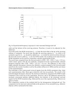
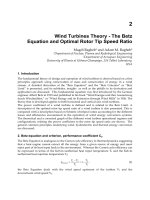
The wind turbine rotational speed and output power as functions of wind speed were
recorded from the experiments, and they are plotted in Figure 15 and 16, respectively.
Wind -Turbine Speed Curve
0
20
40
60
80
100
120
0.00 1.00 2.00 3.00 4.00 5.00 6.00 7.00 8.00 9.00 10.00 11.00 12.00
Wind Speed (m/s)
Turbine Speed (r/min)
Wind Turbine A
Wind Turbine B
Wind Turbine C
Fig. 15. Turbine speed vs. wind speed
It can be seen from these two figures that wind turbines A and with self pitch had good
start-up properties and starting wind speed was about 1.8m/s. However, starting wind
speed of wind turbine B with fixed pitch was above 4m/s. At the same wind speed, the
turbine rotational speed of turbine A was greater than turbine C, and the turbine speed of C
is in turn, greater than B. As the wind speed increased, the output power of turbine A
increases rapidly and reaches the rated value, 300W at 9m/s. At 11m/s wind speed, output
power of wind turbine B is only a quarter of turbine A, and output power of wind turbine C
reaches a half of turbine A.
Magnetic Suspension and Self-pitch for Vertical-axis Wind Turbines
247
Wind Turbine Power Curve
0
50
100
150
200
250
300
350
0.00 1.00 2.00 3.00 4.00 5.00 6.00 7.00 8.00 9.00 10.00 11.00 12.00
Wind Speed (m/s)
Power (W)
Wind Turbine A
Wind Turbine B
Wind Turbine C
Fig. 16. Output power vs. wind speed
Experiment results show that the start-up properties and efficiency of wind utilization were
enhanced in the self-pitch VAWTs due to the implemented self-pitch technology and
optimal design of blades. Magnetic suspended self-pitch VAWT is a new and high-efficiency
wind turbine.
5. Conclusion
In this chapter, the basic principle and main features of a magnetic suspended self-pitch
vertical axis wind turbine have been presented. Compared with the horizontal axis wind
turbine and the traditional vertical axis wind turbine, this new VAWT has the following
advantages:
The magnetic suspension in all degrees of freedom has applied permanent magnets.
The bearing friction and mechanical noise are low. The starting torque, thus the starting
wind speed is low. As a result, the wind turbine consumes little power and has a high
efficiency using wind power.
During rotation, the blades automatically adjust their attack angles to the optimal
values and therefore, generate large lifts.
The wind turbine structure is designed based on aerodynamics and triangular vector
connection method. As a result, the threat of normal blade pressure was mitigated, and
the blade manufacturing cost reduced.
Blades can be made with different sizes as spare parts, which can be used for the same
wind turbine but according to local wind power resource needs. This is a unique feature
not available for other wind turbines.
In order to lower wind power investment, the power capacity of any single wind
turbine should be increased as much as possible. The VAWT presented herein can
easily increase the unit power by simply elongating the turbine wheel arms and
blades.
This VAWT design has a simple structure and low manufacturing cost. It needs no
complicated control mechanism to adjust the blade attack angles. It has a direct-drive
permanent magnet generator with no need of gear box or yawing wind direction
control.
Fundamental and Advanced Topics in Wind Power
248
The blades automatically adjust attack angles to reduce wind thrust, and therefore, can
survive in Typhoon.
This VAWT can start up by itself.
In summary, the new vertical axis wind turbines have adopted magnetic bearings and self-
pitch blade design. Consequently their utilization rate of wind power is improved, overall
efficiency of wind turbine is enhanced, and the production cost as well as maintenance cost
is reduced. The magnetically-suspended self-pitch vertical-axis wind turbines have
irreplaceable advantages and demonstrated the superiority of vertical axis wind turbines.
6. References
TIAN Hai-jiao; WANG Tie-long; WANG Ying. Summarize of the development of the
vertical-axis wind turbine. In : Applied Energy Technology, Vol.6, pp. 22-27, ISSN
1009-3230.
Steinbuch, M. Dynamic modeling and robust control of a wind energy conversion system.
Ph., D. Thesis, University of Delft, Holland 1989.
H. Camblong. Digital robust control of a variable speed pitch regulated wind turbine for
above rated wind speeds. In: Control Engineering Practice, Vol.16, No. 8, pp. 946-
958, ISSN 0967-0661.
Ahmet Serdar Yilmaz a, Zafer Ozer. Pitch angle control in wind turbines above the rated
windspeed by multi-layer perception and radial basis function neural networks. In
: Expert Systems with Applications, Vol. 36, pp. 9767-9775, ISSN 0957-4174.
YANG Hui-jie, YANG Wen-tong. The new development of foreign small vertical axis wind
generators. In : Power Demand Side Management, Vol. 9, No. 2, pp. 68-70, ISSN
1009-1831.
QU Jian-jun, XU Ming-wei, LI Zhong-jie, ZHI Chao. Renewable Energy Resources, Vol. 28,
No. 1, pp. 101-104.
Shuqin Liu, Zhongguo Bian, Deguang Li, Wen Zhao.A Magnetic Suspended Self-pitch
Vertical Axis Wind Generator. Proceedings of Power and Energy Engineering
Conference (APPEEC), ISBN: 978-1-4244-4812-8, chengdu,
March 2010.
HU Ye-faa; XU Kai-guob, et. al. Analysis and Design of Magnetic Bearings Used in Magnetic
Suspending Wind Power Generator. In : Bearing, Vol. 7, pp. 6-10, ISSN 1000-3762.
Global Wind Technology INC, Watkins Philip G. Omni-Directional Wind Turbine Electric
Generation System. America, WO2005108785,2005.
11
The Analysis and Modelling
of a Self-excited Induction
Generator Driven by a
Variable Speed Wind Turbine
Ofualagba, G and Ubeku, E.U
Federal University of Petroleum Resources, Effurun
Nigeria
1. Introduction
Induction machine is used in a wide variety of applications as a means of converting electric
power to mechanical work. The primary advantage of the induction machine is its rugged
brushless construction and no need for separate DC field power. These machines are very
economical, reliable, and are available in the ranges of fractional horse power (FHP) to multi
–megawatt capacity. Also, unlike synchronous machines, induction machines can be
operated at variable speeds. For economy and reliability many wind power systems use
induction machines, driven by a wind turbine through a gear box, as an electrical generator.
The need for gearbox arises from the fact that lower rotational speeds on the wind turbine
side should be converted to high rotor speeds, on the electrical generator side, for electrical
energy production.
There are two types of induction machine based on the rotor construction namely, squirrel
cage type and wound rotor type. Squirrel cage rotor construction is popular because of its
ruggedness, lower cost and simplicity of construction and is widely used in stand-alone
wind power generation schemes. Wound rotor machine can produce high starting torque
and is the preferred choice in grid-connected wind generation scheme. Another advantage
with wound rotor is its ability to extract rotor power at the added cost of power electronics
in the rotor circuit.
This chapter focuses on the electrical generation part of a wind energy conversion system.
After a brief introduction of the induction machine, the electrical generator used in this
chapter, a detailed analysis of the induction machine operated in stand-alone mode is
presented. As a generator, induction machines have the drawback of requiring reactive
power for excitation. This necessitates the use of shunt capacitors in the circuit. The effect of
magnetization inductance on self-excitation of the induction generator is discussed. Also,
this chapter presents the two existing methods to analyze the process of self-excitation in
induction machine and the role of excitation-capacitors in its initiation.
Simulation results of the self-excited induction generator driven by the variable speed wind
turbine are presented in the last section of this chapter. The process of voltage build up and
the effect of saturation characteristics are also explained in the same section.
Fundamental and Advanced Topics in Wind Power
250
2. Induction machine
In the electromagnetic structure of the Induction machine, the stator is made of numerous
coils with three groups (phases), and is supplied with three phase current. The three coils
are physically spread around the stator periphery (space-phase), and carry currents which
are out of time-phase. This combination produces a rotating magnetic field, which is a key
feature of the working of the induction machine. Induction machines are asynchronous
speed machines, operating below synchronous speed when motoring and above
synchronous speed when generating. The presence of negative resistance (i.e., when slip is
negative), implies that during the generating mode, power flows from the rotor to the stator
in the induction machine.
2.1 Equivalent electrical circuit of induction machine
The theory of operation of induction machine is represented by the per phase equivalent
circuit shown in Figure 1 (Krause et al., 1994).
Fig. 1. Per-phase equivalent circuit of the induction machine referred to the stator.
In the above figure, R and X refer to the resistance and inductive reactance respectively.
Subscripts 1, 2 and m represent stator, rotor values referred to the stator side and
magnetizing components, respectively.
Induction machine needs AC excitation current for its running. The machine is either self-
excited or externally excited. Since the excitation current is mainly reactive, a stand-alone
system is self-excited by shunt capacitors. In grid-connected operation, it draws excitation
power from the network, and its output frequency and voltage values are dictated by the
grid. Where the grid capacity of supplying the reactive power is limited, local capacitors can
be used to partly supply the needed reactive power (Patel, 1999).
3. Self-Excited Induction Generator (SEIG)
Self-excited induction generator (SEIG) works just like an induction machine in the
saturation region except the fact that it has excitation capacitors connected across its stator
terminals. These machines are ideal choice for electricity generation in stand-alone variable
speed wind energy systems, where reactive power from the grid is not available. The
induction generator will self-excite, using the external capacitor, only if the rotor has an
adequate remnant magnetic field. In the self-excited mode, the generator output frequency
and voltage are affected by the speed, the load, and the capacitance value in farads (Patel,
1999). The steady-state per-phase equivalent circuit of a self-excited induction generator is
shown in the Figure 2.
The Analysis and Modelling of a Self-excited
Induction Generator Driven by a Variable Speed Wind Turbine
251
Fig. 2. Self-excited induction generator with external capacitor.
The process of self-excitation in induction machines has been known for many decades
(Basset & Potter, 1935). When capacitors are connected across the stator terminals of an
induction machine, driven by an external prime mover, voltage will be induced at its
terminals. The induced electromotive force (EMF) and current in the stator windings will
continue to rise until the steady-state condition is reached, influenced by the magnetic
saturation of the machine. At this operating point the voltage and the current will be
stabilized at a given peak value and frequency. In order for the self-excitation to occur, for a
particular capacitance value there is a corresponding minimum speed (Wagner, 1935). So, in
stand-alone mode of operation, it is necessary for the induction generator to be operated in
the saturation region. This guarantees one and only one intersection between the
magnetization curve and the capacitor reactance line, as well as output voltage stability
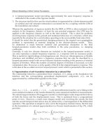
under load as seen in the Figure 3:
Fig. 3. Determination of stable operation of self-excited induction generator.
At no-load, the capacitor current I
c
=V
1
/X
c
must be equal to the magnetizing current
I
m
=V
1
/X
m
. The voltage V
1
is a function of I
m
, linearly rising until the saturation point of the
magnetic core is reached. The output frequency of the self-excited generator is, f=1/(2πCX
m
)
and ω=2πf where C is self-exciting capacitance.
4. Methods of analysis
There are two fundamental circuit models employed for examining the characteristics of a
SEIG. One is the per-phase equivalent circuit which includes the loop-impedance method
adopted by (Murthy et al, 1982) and (Malik & Al-Bahrani, 1990), and the nodal admittance
method proposed by (Ouazene & Mcpherson, 1983) and (Chan, 1993). This method is
Fundamental and Advanced Topics in Wind Power
252
suitable for studying the machine’s steady-state characteristics. The other method is the dq-
axis model based on the generalized machine theory proposed by (Elder et al., 1984) and
(Grantham et al., 1989), and is employed to analyze the machine’s transient state as well as
steady-state.
4.1 Steady-state model
Steady-state analysis of induction generators is of interest both from the design and
operational points of view. By knowing the parameters of the machine, it is possible to
determine the performance of the machine at a given speed, capacitance and load conditions.
Loop impedance and nodal admittance methods used for the analysis of SEIG are both
based on per-phase steady-state equivalent circuit of the induction machine (Figure 4),
modified for the self-excitation case. They make use of the principle of conservation of active
and reactive powers, by writing loop equations (Murthy et al, 1982], (Malik & Al-Bahrani,
1990), (Al-Jabri & Alolah, 1990) or nodal equations (Ouazene & Mcpherson, 1983), (Chan,
1993), for the equivalent circuit. These methods are very effective in calculating the
minimum value of capacitance needed for guaranteeing self-excitation of the induction
generator. For stable operation, excitation capacitance must be slightly higher than the
minimum value. Also there is a speed threshold, below which no excitation is possible,
called as the cutoff speed of the machine. In the following paragraph, of loop impedance
method is given for better understanding.
The per-unit per-phase steady-state circuit of a self-excited induction generator under RL
load is shown in Figure 4 (Murthy et al., 1982), (Ouazene & Mcpherson, 1983).
Fig. 4. Equivalent circuit of self-excited induction generator with R-L Load.
Where:
R
s
, R
r
, R : p.u. per-phase stator, rotor (referred to stator) and load resistance respectively.
Xls, Xlr, X, Xm : p.u. per-phase stator leakage, rotor leakage (referred to stator), load and
magnetizing reactances (at base frequency), respectively.
Xsmax : p.u. maximum saturated magnetizing reactance.
C : per-phase terminal-excitation capacitance.
Xc : p.u. per-phase capacitive reactance (at base frequency) of the terminal excitation
capacitor.
f, v : p.u.frequency and speed, respectively.
N : base speed in rev/min
Z
b
: per-phase base impedance
fb : base frequency
V
g
, V
0
: per-phase air gap and output voltages, respectively.
The Analysis and Modelling of a Self-excited
Induction Generator Driven by a Variable Speed Wind Turbine
253
In the analysis of SEIG the following assumptions were made (Murthy et al., 1982):
1. Only the magnetizing reactance Xm is assumed to be affected by magnetic saturation,
and all other parameters of the equivalent circuit are assumed to be constant. Self-
excitation results in the saturation of the main flux and the value of X
m
reflect the
magnitude of the main flux. Leakage flux passes mainly in the air, and thus these fluxes
are not affected to any large extent by the saturation of the main flux.
2. Stator and rotor leakage reactance, in per-unit are taken to be equal. This assumption is
normally valid in induction machine analysis.
3. Core loss in the machine is neglected.
For the circuit shown in Figure 4, the loop equation for the current can be written as:
I Z = 0 (1)
Where Z is the net loop impedance given by
Z =
‖
+
+ j
+
(2)
Since at steady-state excitation I ≠0, it follows from (equation 1) that Z = 0 , which implies
that both the real and imaginary parts of Z are zeros. These two equations can be solved
simultaneously for any two unknowns (usually voltage and frequency). For successful
voltage-buildup, the load-capacitance combination and the rotor speed should result in a
value such that X
m
=X
smax
, which yields the minimum value of excitation capacitance below
which the SEIG fails to self-excite.
4.2 Steady-state and transient model (abc-dq0 transformation)
The process of self-excitation is a transient phenomenon and is better understood if
analyzed using a transient model. To arrive at transient model of an induction generator,
abc-dq0 transformation is used.
4.2.1 abc-dq0 transformation
The abc-dq0 transformation transfers an abc (in any reference frame) system to a rotating dq0
system. (Krause et al., 1994) noted that, all time varying inductances can be eliminated by
referring the stator and rotor variables to a frame of reference rotating at any angular
velocity or remaining stationary. All transformations are then obtained by assigning the
appropriate speed of rotation to this (arbitrary) reference frame. Also, if the system is balanced
the zero component will be equal to zero (Krause et al., 1994).
A change of variables which formulates a transformation of the 3-phase variables of stationary
circuit elements to the arbitrary reference frame may be expressed as (Krause et al., 1994):
F
qdos
= K
sfabcs
(3)
Where:
F
qdo
s =
;f
abc
s =
;K
s
=
;
0
;