Advances in Vibration Analysis Research Part 5 docx
Bạn đang xem bản rút gọn của tài liệu. Xem và tải ngay bản đầy đủ của tài liệu tại đây (1.11 MB, 30 trang )
Free Vibration of Smart Circular Thin FGM Plate
109
To solve Eq. (34) for w, we first assume that;
(
)
1
(, ,) ()
im t
wr t w re
θ
ω
θ
−
=
(34)
where
1
()wr
is the displacement amplitude in the z - direction as a function of radial
displacement only;
ω
is the natural angular frequency of the compound plate; and m is the
wave number in the circumferential direction. Rewriting Eq. (32) in terms of
1
()wr and
using Eq. (34), after canceling the exponential term one would get;
22
31211101
0PwPw Pw Pw
ΔΔΔ ΔΔ ω Δ ω
−
−+=
(35)
where
22 22
ddr drdrmr
Δ
=+−
Eq. (35) can be solved by the method of decomposition operator and noting that the
1
w is
non-singular at the center of the plate its general solution yields to
3
1
1
()
nm nm n
n
wAZr
α
=
=
∑
(36)
here
11
x
α
= ,
22
x
α
= ,
33
x
α
= (37)
in which x
1
, x
2
and x
3
are the roots of the following cubic characteristic equation,
322 2
32 1 0
0Px Px Px P
ωω
−
−+= (38)
and
(), 0
() (,)
(), 0
mi i
im i im i
mi i
Jrx
ZrZ r
Irx
α
αα
α
<
⎧
==
⎨
>
⎩
(39)
here
i=(1,2,3) and
()
mi
Jr
α
,
()
mi
Ir
α
are the first type and the modified first type Bessel
function ,both of them of the order of m. In order to obtain appropriate solution for
(, ,)rt
ϕ
θ
,
we assume;
(
)
1
(, ,) ()
im t
rt re
θ
ω
ϕθ ϕ
−
= (40)
then substituting Eq. (36) in to Eq. (31)we arrive to the following relation for
(, ,)rt
ϕ
θ
;
3
1
22
13133 31
1
42
12 110 11
() 16 (2
() )()
nm p n n p
n
nnmn
re Ahshe
DD P Z r
ϕΞ α
αΞ ωΞ α
−
=
⎡
⎡⎤
=
−
⎣⎦
⎣
⎤
++×
⎦
∑
(41)
7. Case studies, results and discussions
We will solve above the relations in this section; the material parameters and geometries are
listed in Table 1.
Advances in Vibration Analysis Research
110
FGM Plate: E
c
= 205 GPa ρ
c
=8900 (kg/ m
3
)
E
m
= 200 GPa ρ
m
=7800
PZT4:
11
E
C
=
132
33
E
C
=
115
55
E
C
=
26 GPa
13
E
C
=
73
12
E
C
=
71
e
31
=-4.1 (C/m
2
) e
33
=14.1 e
15
=10.5
11
Ξ
=7.124 (nF/m)
33
Ξ
=5.841
ρ
p
=7500 (kg/ m
3
)
Geometry(mm): r
0
=600 h
f
=2, h
p
=10
Table 1. Material properties and geometric size of the piezoelectric coupled FGM plate [13,17]
7.1 Clamped circular piezo-coupled FGM plate
The boundary condition is given by
11 1 0
0( )wdwdrddr atrr
ϕ
=== =
(42)
and the characteristic equation is
11 12 13
21 22 23
31 32 33
0
ccc
ccc
ccc
=
(43)
10200
23 5 4
0 1 2 0 11 1 2 11
3 0
223
31 31 0
(), ()
() ()
()
8
16 16
iimi iiimi
pii p i pi
i im i
cZ r c rZ r
hrs D Dhr D Dh
cZr
eer
ααα
ααΞαλΞ
α
′
==
⎛⎞
++
⎜⎟
′
=− +
⎜⎟
⎝⎠
(44)
1
2
4
0
12
2( )
ff pp
hh
r
DD
ρρω
λ
⎡
⎤
+
⎢
⎥
=
+
⎢
⎥
⎣
⎦
(45)
2
12
2
0
2( )
ff pp
DD
hh
r
λ
ω
ρρ
+
=
+
(46)
in which the ()’ symbol indicates the derivative with respect to r and λ is the
nondimensional angular natural frequency.
After calculating
ω
from Eq. (43) and using Eqs. (36, 42) we find the mode shape for w
1
as;
3 2 20 3 30 2 3 30 2 20
13 11
2110220 1220110
1330110 3110330
21 10 2 20 12 20 1 1
()() ()()
() ( )
()() ()()
()() ()()
()() ()(
mm mm
m m
mm mm
mm mm
mm mm
ZrZr ZrZr
wr A Z r
ZrZr ZrZr
ZrZr ZrZr
ZrZr ZrZr
αα ααα α
α
αα ααα α
αα ααα α
αα ααα α
⎡
⎛⎞
′′
−
=× × +
⎢
⎜⎟
′′
−
⎢
⎝⎠
⎣
′′
−
′′
−
]
22 33
0
() ()
)
mm
ZrZr
αα
⎛⎞
×+
⎜⎟
⎝⎠
(47)
and moreover, by using Eqs. (36, 41, 42) we have the electric potential as;
Free Vibration of Smart Circular Thin FGM Plate
111
3220330 2330220
3
2110220 1220110
1
22 4 2
1 1 1 1 31 1 2 1 11 0 11 31 33
13 30 1
()() ()()
ˆ
()
()() ()()
( ) (2 ( ) ) 16
()
mm mm
m
mm mm
mpp
mm
ZrZr ZrZr
rA
ZrZr ZrZr
ZrhsheDD P e
ZrZ
αα ααα α
ϕ
αα ααα α
αα αΞωΞΞ
αα
−
⎡
⎛⎞
′′
−
=× ×
⎢
⎜⎟
′′
−
⎢
⎝⎠
⎣
⎡⎤
⎡⎤
×× −+ + × +
⎣⎦
⎣⎦
′
+
10 3 1 10 3 30
2110220 1220110
1
22 4 2
2 2 2 2 31 1 2 2 11 0 11 31 33
22 4 2
3 3 31 1 2 3 11 0 11
() ()()
()() ()()
( ) (2 ( ) ) 16
(2 ( ) ) 16
mm
mm mm
mpp
pp
rZrZr
ZrZr ZrZr
ZrhsheDD P e
hs he DD P
ααα α
αα ααα α
αα αΞωΞΞ
ααΞωΞ
−
⎛⎞
′
−
×
⎜⎟
′′
−
⎝⎠
⎡⎤
⎡⎤
×× −+ + × +
⎣⎦
⎣⎦
⎡⎤
+−++×
⎣⎦
1
31 33 3 3
()
m
eZr
Ξα
−
⎤
⎡⎤
⎣⎦
⎥
⎦
(48)
Power
Index
Mode
no.
FGM plate
g m Present
Method
Present
(FEM)
Error
(%)
Wang
et al.
[13]
0 138.42 139.27 0.61 138.48
1 288.05 289.70 0.57 288.20
0
2 472.55 473.45 0.19 472.79
0 134.63 135.43 0.59 -
1 280.17 281.78 0.57 -
1
2 459.62 460.45 0.18 -
0 132.70 133.63 0.69 -
1 276.19 278.04 0.67 -
3
2 453.09 454.34 0.28 -
0 132.12 133.06 0.70 -
1 274.96 276.85 0.68 -
5
2 451.06 452.39 0.29 -
0 131.85 132.78 0.70 -
1 274.39 276.25 0.67 -
7
2 450.13 451.46 0.29 -
0 131.69 132.70 0.76 -
1 274.07 276.09 0.73 -
9
2 449.60 450.84 0.28 -
0 131.64 132.55 0.68 -
1 273.96 275.79 0.67 -
10
2 449.42 450.66 0.28 -
Table 2. First three resonance frequencies (Hz) of FGM plate
In order to validate the obtained results, we compared our results with those given in the
literature [7,9,10].Further as there were no published results for the compound piezoelectric
FGM plate, we verify the validity of obtained results with those of FEM results.
Advances in Vibration Analysis Research
112
Our FEM model for piezo- FG plate comprises: a 3D 8-noded solid element with: number of
total nodes 26950, number of total element 24276, 3 DOF per node in the host plate element
and 6 DOF per node in the piezoelectric element. Tables 2 and 3 shows the numerical results
of our method compared with other references and techniques.
As one can see from Table 2, the obtained results from the analytical method when g=0
(isotropic steel plate) corresponds closely with the results of [7-9] and FEM solution. As it is
seen in these tables the maximum estimated error of our solution with FEM is about 1.51%.
Power
Index
Mode
no.
Coupled Piezo-FGM plate
g m Present
Method
Present
(FEM)
Error
(%)
Wang
et al.
[13]
0 143.63 144.69 0.73 143.71
1 298.92 300.49 0.52 299.070
2 490.37 492.62 0.46 490.62
0 140.26 142.22 1.38 -
1 291.89 295.82 1.33 - 1
2 478.84 482.09 0.67 -
0 138.54 140.60 1.46 -
1 288.33 292.47 1.42 - 3
2 472.99 476.61 0.76 -
0 138.01 140.07 1.47 -
1 287.21 291.39 1.43 - 5
2 471.16 474.81 0.77 -
0 137.76 139.82 1.47 -
1 286.69 290.83 1.43 - 7
2 470.30 473.95 0.77 -
0 137.62 139.73 1.51 -
1 286.40 290.54 1.43 - 9
2 469.83 473.16 0.70 -
0 137.57 139.61 1.46 -
1 286.30 290.41 1.42 - 10
2 469.66 473.26 0.76 -
Table 3. First three resonance frequencies (Hz) for piezo-coupled FGM plate for various
values of power index
A close inspection of results listed in Tables 2 and 3 indicates that the amount of error between
analytical and FEM results for the natural frequencies in FGM plate alone in the all vibration
modes and for all values of g are less than the similar results for the compound plate.
The obtained results in Table 3 indicate that by increasing the value of g, the frequency of
system decreases in all different vibrational modes. Moreover, this decreasing trend of
frequency for smaller values of g is more pronounced, for example by increasing value of g
from 1 to 3 (~200%) the frequency of the first mode for the compound plate decreases by
Free Vibration of Smart Circular Thin FGM Plate
113
130
132
134
136
138
140
142
144
146
0246810
Power Index(g)
Natural Frequency (Hz)
FGM Plate-Analytical FGM Plate-FEM
Piezo coupled FGM-Analytical Piezo coupled FGM-FEM
Fig. 2. Effect of power index on the natural frequencies (first mode)
445
450
455
460
465
470
475
480
485
490
495
0246810
Power Index(g)
Natural Frequency (Hz)
FGM Plate-Analytical FGM Plate-FEM
Piezo coupled FGM-Analytical Piezo coupled FGM-FEM
Fig. 3. Effect of power index on the natural frequencies (third mode)
1.23% but by increasing g from 3 to 9 (~ 200%) of the same plate and for the same mode, the
frequency decreases by 0.66%. In order to see better the effect of g variations on the natural
frequencies of the different plates, Fig. 2 and Fig. 3 also illustrate these variations for the first
and third mode shapes.
As it is seen from Figs. 2 and Fig. 3, the behavior of the system follows the same trend in all
different cases, i.e. the natural frequencies of the system decrease by increasing of g and
stabilizes for g values greater than 7. In fact for g>>1 the FGM plate becomes a ceramic plate
and the compound plate transforms to a laminated plate with ceramic core as a host plate.
Advances in Vibration Analysis Research
114
8. Conclusion
In this paper free vibration of a thin FGM plus piezoelectric laminated circular plate based
on CPT is investigated. The properties of FG material changes according to the Reddy’s
model in direction of thickness of the plate and distribution of electric potential in the
piezoelectric layers follows a quadratic function in short circuited form. The validity of the
obtained results was done by crossed checking with other references as well as by obtained
results from FEM solutions. It is further shown that for vibrating circular compound plates
with specified dimensions, one can select a specific piezo-FGM plate which can fulfill the
designated natural frequency and indeed this subject has many industrial applications.
9. References
[1] Koizumi M. concept of FGM. Ceram. Trans. 1993; 34: 3–10.
[2] Bailey T, Hubbard JE. Distributed piezoelectric polymer active vibration control of a
cantilever beam. J. Guidance, Control Dyn. 1985; 8: 605-11.
[3] Millerand SE, Hubbard JE. Observability of a Bernoulli–Euler beam using PVF2 as a
distributed sensor. MIT Draper Laboratory Report, 1987.
[4] Peng F, Ng A, Hu YR. Actuator placement optimization and adaptive vibration control of
plate smart structures. J. Intell. Mater. Syst. Struct. 2005; 16: 263–71.
[5] Ootao Y, Tanigawa Y. Three-dimensional transient piezo-thermo-elasticity in
functionally graded rectangular plate bonded to a piezoelectric plate. Int. J. Solids
Struct. 2000; 37: 4377–401.
[6] Reddy JN, Cheng ZQ. Three-dimensional solutions of smart functionally graded plates.
ASME J. Appl. Mech 2001; 68: 234–41.
[7] Wang BL, Noda N. Design of smart functionally graded thermo-piezoelectric composite
structure. Smart Mater. Struct. 2001; 10: 189–93.
[8] He XQ, Ng TY, Sivashanker S, Liew KM. Active control of FGM plates with integrated
piezoelectric sensors and actuators. Int. J. Solids Struct.2001; 38: 1641–55.
[9] Yang J, Kitipornchai S, Liew KM. Non-linear analysis of thermo-electro-mechanical
behavior of shear deformable FGM plates with piezoelectric actuators. Int. J.
Numer. Methods Eng. 2004; 59:1605–32.
[10] Huang XL, Shen HS. Vibration and dynamic response of functionally graded plates with
piezoelectric actuators in thermal environments. J. Sound Vib. 2006; 289: 25–53.
[11] Reddy JN, Praveen GN. Nonlinear transient thermoelastic analysis of functionally
graded ceramic-metal plate. Int. J. Solids Struct 1998; 35: 4457-76.
[12] Wetherhold RC, Wang S. The use of FGM to eliminate or thermal deformation.
Composite Sci Tech 1996; 56: 1099-104.
[13] Wang Q, Quek ST, Liu X. Analysis of piezoelectric coupled circular plate. Smart Mater.
Struct 2001; 10: 229-39.
[14] Reddy J.N, Theory and analysis of elastic plates, Philadelphia: Taylor and Francis, 1999.
[15] Halliday D, Resniek R. Physics, John Wiley and Sons, 1978.
[16] Brush DO, Almroth BO. Buckling of bars plates and shells. New York: Mac-hill, 1975.
[17] Loy CT, Lam KL, Reddy JN. Vibration of functionally graded cylindrical shells. Int. J
Mech Sciences 1999;41: 309-24
7
An Atomistic-based Spring-mass
Finite Element Approach for
Vibration Analysis of
Carbon Nanotube Mass Detectors
S.K. Georgantzinos and N.K. Anifantis
Machine Design Laboratory
Mechanical and Aeronautics Engineering Department
University of Patras, GR 26500
Greece
1. Introduction
Since their discovery in 1991 by Ijima [1], carbon nanotubes (CNT) have received much
attention as a new class of nanomaterials revealing a significant potential for use in a diverse
range of novel and evolving applications. Much of the interest in CNTs has focused on their
particular molecular structures and their unique electronic and mechanical properties. For
example, their elastic stiffness is comparable to that of diamond (1000 GPa), while their
strength is ten times larger (yield strength 100 GPa). Furthermore, CNTs conduct heat and
electricity along their length with very little resistance, and therefore they act as tiny
electrical wires or paths for the rapid diffusion of heat. As a result, progressive research
activities regarding CNTs have been ongoing in recent years. For more detail on theoretical
predictions and experimental measurements of both mechanical and physical properties, see
the comprehensive reviews in [2,3].
The combination of an extremely high stiffness and light weight in CNTs results in vibration
frequencies on the order of GHz and THz. There is a wide range of applications in which the
vibrational characteristics of CNTs are significant. In applications such as oscillators, charge
detectors, field emission devices, vibration sensors, and electromechanical resonators,
oscillation frequencies are key properties. An representative application is the development
of sensors for gaseous molecules, which play significant roles in environmental monitoring,
chemical process control, and biomedical applications. Mechanical resonators are widely
used as inertial balances to detect small quantities of adsorbed mass through shifts in
oscillation frequency. Recently, advances in lithography and materials synthesis have
enabled the fabrication of nanoscale mechanical resonators that utilize CNTs [4,5]. The use
of a CNT to make the lightest inertial balance ever is essentially a target to make a nanoscale
mass spectrometer of ultrahigh resolution. Building such a mass spectrometer that is able to
make measurements with atomic mass sensitivity is one of the main goals in the burgeoning
field of nanomechanics. An inertial balance relies only on the mass and does not, therefore,
require the ionization or acceleration stages that might damage the molecules being
Advances in Vibration Analysis Research
116
measured. This means that a nanoscale inertial balance would be able to measure the mass
of macromolecules that might be too fragile to be measured by conventional instruments [5].
Several efforts for the building of CNT-based sensors have been presented in the literature.
Mateiu et al. [6] described an approach for building a mass sensor based on multi-walled
CNTs with an atomic force microscope. Chiu et al. [7] demonstrated atomic-scale mass
sensing using doubly clamped, suspended CNT resonators in which their single-electron
transistor properties allowed the self-detection of nanotube vibration. They used the
detection of shifts in the resonance frequency of the nanotubes to sense and determine the
inertial mass of atoms as well as the mass of the nanotube itself. Commonly, multi-walled
CNTs are less sensitive than single-walled CNTs. However, multi-walled carbon nanotubes
are easier to manipulate and more economical to be produced, since they are both longer
and have larger diameters than single-walled CNTs [8].
Hence, it is important to develop accurate theoretical models for evaluation of natural
frequencies and mode shapes of CNTs. An excellent review article was recently published
by Gibson et al. [9] that presents related scientific efforts in dealing with the vibrational
behavior of CNTs and their composites, including both theoretical and experimental studies.
Controlled experiments performed at nanoscale dimensions remain both difficult and
expensive. Despite of this fact, Garcia-Sanchez et al. [10] have recently presented a
mechanical method for detecting CNT resonator vibrations using a novel scanning force
microscopy method. The comparison between experimental and theoretical methods pre-
require the complete definition of all parameters such as the length of the vibrating
nanotube, the nanotube type and other conditions that influence the vibrational behavior
such as the slack phenomenon, nature of the support condition, environmental conditions
and other influences.
In an attempt to approach the vibration behavior of CNTs, various theoretical methods have
been reported in literature. Molecular dynamics (MD) and molecular mechanics, as well as
elastic continuum mechanics, are considered efficient because they can accurately and cost-
effectively produce results that closely approximate the behavior of CNTs. . Each of the
previously mentioned approaches offers different advantages, but also certain drawbacks.
MD is an accurate method capable of simulating the full mechanical CNT performance.
However, it carries a high computational cost that may be prohibitive for large-scale
problems, especially in the context of vibration analysis. Molecular mechanics-based
techniques, such as those in [11-13], have been used for vibration analysis of CNTs and have
been shown to be accurate and also more computationally cost-effective than MD.
Nevertheless, under such approaches, the modeling of atomic interactions requires special
attention because the mechanical equivalent used to simulate the carbon-carbon bond
deformations must be efficient for the studied problem. Generally, typical elements of
classical mechanics, such as rods [14], beams [15, 16], springs [17-19] and cells [20] have been
proposed including appropriate stiffness parameters, thus their strain energies are
equivalent to the potential energies of each interatomic interaction. Furthemore, elastic
continuum mechanics methods based on well-known beam theories have also been
successfully used to evaluate the vibration characteristics of CNTs under typical boundary
conditions [21-24]. Xu et al. [25] studied the free vibration of double-walled CNTs modeled
as two individual beams interacting with each other taking van der Waals forces into
account and supported with different boundary conditions between the inner and outer
tubes. These methods have the lowest computational cost; however, they can compute only
a subset (mainly the bending modes) of the vibrational modes and natural frequencies.
An Atomistic-based Spring-mass Finite Element Approach for
Vibration Analysis of Carbon Nanotube Mass Detectors
117
In terms of CNT mass detector function, the principle of mass detection using CNT-based
resonators is based on the fact that the vibrational behavior of the resonator is sensitive to
changes in its mass due to attached particles. The change of the resonator mass due to an
added mass causes frequency shifts. The key challenge in mass detection is quantifying the
changes in the resonant frequencies due to added masses. Based on this principle, the usage
of computational tools, as presented in prevous paragraph, capable of simulating the
vibrational behavior of CNT-based mass detectors is important for two reasons. First, they
can cost-effectively predict the mass sensing characteristics of different nanoresonator types,
thereby allowing the optimal design of detectors with a specific sensing range. Second, their
cooperation with experimental measurements can improve the detection abilities of the
nanodevice. With respect to theoretical studies on CNT-based sensors, Li and Chou [26]
examined the potential of nanobalances using individual single-walled CNTs in a
cantilevered or bridged configuration. Wu et al. [27] explored the resonant frequency shift of
a fixed-free single-walled CNT caused by the addition of a nanoscale particle to the beam
tip. This was done to explore the suitability of a single-walled CNT as a mass detector
device in a micro-scale situation via a continuum mechanics-based finite element method
simulation using a beam-bending model. Chowdhury et al. [28] examined the potential of
single-walled CNTs as biosensors using a continuum mechanics-based approach and
derived a closed-form expression to calculate the mass of biological objects from the
frequency shift.
In this chapter, an atomistic spring-mass based finite element approach appropriate to
simulate the vibration characteristics of single-walled and multi-walled CNTs is presented.
The method uses spring-mass finite elements that simulate the interatomic interactions and
the inertia effects in CNTs. It uses a special technique for simulating the bending between
adjacent bonds, distinguishing it from other mechanics-based methods. This method utilizes
the exact microstructure of the CNTs while allowing the straightforward input of the force
constants that molecular theory provides. In addition, spring-like elements are formulated
in order to simulate the interlayer van der Waals interactions. These elements connect all
atoms between different CNT layers at a distance smaller than the limit below which the
van der Waals potential tends to zero. The related stiffness is a function of this distance. The
resulting dynamic equilibrium equations can be used to generate new results. Results
available in the literature were used to validate the proposed method. Parametric analyses
are performed reporting the natural frequencies as well as the mode shapes of various
multi-walled CNTs for different aspect geometric characteristics. Furthermore, the principle
of mass detection using resonators is based on the fact that the resonant frequency is
sensitive to the resonator mass, which includes the self-mass of the resonator and the
attached mass. The change of the attached mass on the resonator causes a shift to the
resonant frequency. Since, the key issue of mass detection is in quantifying the change in the
resonant frequency due to the added mass, the effect of added mass to the vibration
signature of CNTs is investigated for the clamped-free and clamped-clamped support
conditions. And different design parameters. Additionally, the frequency shifts of single-
and multi-walled CNTs were compared.
2. CNTs geometry
A planar layer of carbon atoms forms a periodic structure called the graphene sheet. Pencil
lead consists of a stack of overlaying graphene sheets that easily separate upon shearing in
Advances in Vibration Analysis Research
118
writing. A perfect graphene sheet in the xy-plane consists of a doubly periodic hexagonal
lattice defined by two base vectors,
(
)
1,0a=
1
v and
()
13
cos60 ,sin60 ,
22
oo
aa
⎛⎞
==
⎜⎟
⎜⎟
⎝⎠
2
v (1)
where α is equal to
3
h
r and
h
r is the radius of the hexagonal cell. Note that the lengths of
these vectors are equal. Any point of plane
(,)Pxy
=
is uniquely defined as a linear
combination of these two vectors,
1
ab=+ +
02
Pv v v, (2)
where
a and b are integers, provided that
0
v
is the center of a hexagon.
Knowing the geometry of graphene, a single-walled CNT can be geometrically generated by
rolling a single-layer graphene sheet, which is ideally cut, to make a cylinder. The graphene
sheet must be rolled up in the direction of the chiral vector
h
C
defined as (see Figure 1):
12
nm
=
+
h
Caa (3)
where
1
a and
2
a are the basis vectors of the honeycomb lattice and integers ( n , m ) are the
number of steps along the zigzag carbon bonds and generally are used to name a nanotube.
Fig. 1. Generation of a SWCNT from a graphene sheet.
An Atomistic-based Spring-mass Finite Element Approach for
Vibration Analysis of Carbon Nanotube Mass Detectors
119
A nanotube ( n , n ) is usually named as armchair (Figure 2(a)) while the nanotube ( n ,0) is
usually named zigzag (Figure 2(b)). The chiral angle
ψ
(
o
030
ψ
≤≤ ) is defined as:
3
tan
(2 )
m
nm
ψ
=
+
(4)
It is obvious that for an armchair nanotube
o
30
ψ
= while for a zigzag
o
0
ψ
= . The
nanotube’s diameter
D is given by the following equation:
22
cc
3( )annmm
D
π
−
++
=
(5)
where
cc−
a is distance between two neighbor carbon atoms and is equal to 0.1421 nm.
Chiral vector
h
C and the following translational vector T define the ideal rectangular
cutting area of graphene sheet:
12
22mn nm
WW
+
+
⎛⎞⎛ ⎞
=+−
⎜⎟⎜ ⎟
⎝⎠⎝ ⎠
Ta a
(6)
where
W defines the higher common divisor of 2mn
+
and 2nm
+
.
(a)
(b)
Fig. 2. Geometry of an (a) armchair and (b) zigzag single-walled CNTs
Advances in Vibration Analysis Research
120
For simplicity, the original coordinate system of the graphene sheet (', ')xy is transformed
into a new system
(, ,)xyz of the nanotube such that T is along '
y
-axis. Then, the
graphene atomic coordinates are converted to those of the nanotube according to the
equation (Kołoczek et al. [29]):
''
(, ,) cos , sin , '
xx
xyz R r y
RR
⎛⎞
⎛⎞ ⎛⎞
=
⎜⎟
⎜⎟ ⎜⎟
⎝⎠ ⎝⎠
⎝⎠
(7)
where
R is the nanotube’s radius.
A multi-walled CNT consists of multiple layers of graphene rolled in on themselves to form
a tube shape. In other words, every multi-walled CNT consists of more than one coaxial
single-walled CNTs. Since single-walled CNTs are parts of multi-walled CNTs, the layers of
multi-walled CNTs have similar geometric characteristics. Given that the interlayer distance
is 0.34nm, as has been observed in [1], the difference between diameters of neighbouring
layers, where the diameter of every layer can be calculated using the Equation (5), is
∆D=0.68nm. Knowing that this equation is a function only of chirality indexes of the two
neighboring nanotubes in a multi-walled CNT, someone can calculate the convenient types
of single-walled CNTs able to apart the multi-walled CNT of
Fig. 3. Geometry of a multi-walled CNT.
specific number of layers and outer diameter. If
11
(, )nm and
22
(, )nm are the types of the
inner and outer neighboring layers respectively, it is observed that for zig-zag nanotubes,
the chirality indexes are
21
9nn
=
+ and
21
0mm
=
= . Correspondingly, if the neighboring
nanotubes are armchair then
221
5nmn
=
=+ and
11
mn
=
. The type of one MWCNT, here,
is declared as the sequence of the types of all layers
(, ) ( , )
in in out out
nm n m−−
, starting from
the type of the innermost tube and finishing to the type of the outermost tube. A
representative example of multi-walled CNT geometry consists of three layers is depicted in
Figure 3.
An Atomistic-based Spring-mass Finite Element Approach for
Vibration Analysis of Carbon Nanotube Mass Detectors
121
3. Computational model
3.1 Force field
The total potential energy, omitting non-bonded interactions, i.e. the electrostatic energy
and the energy due to van der Waals interaction, is a sum of energies caused by the bonded
interatomic interactions, which are depicted in Figure 4(a), and may be expressed by the
following equation (Rappe et al. [30]):
r
UU U U U
θ
φω
=
+++
∑
∑∑∑
(8)
where
r
U represents the energy due to bond stretching, U
θ
the energy due to bond angle
bending,
U
φ
the energy due to dihedral angle torsion andU
ω
the energy due to out of plane
torsion.
bond streching
Out of plane
torsion
bond angle
bending
Dihedral angle
torsion
k
b1
k
b2
k
b3
k
τ
k
r
(a) (b)
Fig. 4. Force field in neighboring atoms (a) interatomic interactions and (b) spring model.
Under the assumption of small deformations, the harmonic approximation is adequate for
describing potential energy (Gelin [31]) and therefore the force field. By adopting the
simplest harmonic forms and combining the dihedral angle, torsion with the out of plane
torsion into a single equivalent term then the following terms can describe the total potential
energy [17]:
2
1
()
2
rr
Ukr
Δ
=
,
2
2
r
r
dU
k
dr
Δ
=
(9)
2
1
()
2
Uk
θθ
Δ
θ
=
,
2
2
θ
dU
k
d
θ
Δ
θ
=
(10)
2
1
()
2
UUU k
τϕω τ
Δφ
=+= ,
2
2
dU
k
d
τ
τ
Δ
τ
=
(11)
Advances in Vibration Analysis Research
122
where
r
k , k
θ
and k
τ
are the bond stretching, bond angle bending, and torsional resistance
force constants, respectively, while
r
Δ
,
Δ
θ
and
Δ
φ
represent the bond length, bond angle
and twisting bond angle variations, respectively.
The second derivatives of the potential energy terms appearing in equations (7), (8) and (9)
with respect to bond stretch, bond angle and twisting bond angle variations, respectively,
produce spring stiffness coefficients
r
k , k
θ
and k
τ
. Thus, here, axial and torsional springs
that straightforwardly introduce the physical constants are utilized (Figure 4(b)) in order to
describe the force field. The springs interconnect the nodes that have been extracted from
the eq. (3). The bond angle bending interaction is simulated by axial springs, which have
stiffness
2
o
cc
1
cos(90 )
bi
kk
a
θ
γ
−
⎛⎞
=
⎜⎟
⎜⎟
−
⎝⎠
(12)
as has been described in [17], where
o
30
γ
= in the hexagonal lattice of the graphene. This
angle may vary for each C-C-C microstructure in a CNT according to its type and radius
due to its cylindrical shape. In the case of chiral nanotubes, the stiffness of the three different
bending springs (Figure 4(b)) varies
123bbb
kkk≠≠. In the cases of armchair and zigzag
nanotubes, two of the three bending spring stiffnesses are equal due to the same angle
γ
. In
the other hand, because of the planar shape of the graphene sheets, all the bond angle
bending springs have the same stiffness, i.e.
123bbb
kkk==.
The interlayer interactions between the walls of a multi-walled CNT is caused by the van
der Waals forces and can described through the Lennard-Jones pair potential [32,33]
12 6
() 4
σσ
UR
RR
ε
⎡
⎤
⎛⎞ ⎛⎞
=−
⎢
⎥
⎜⎟ ⎜⎟
⎝⎠ ⎝⎠
⎢
⎥
⎣
⎦
(13)
where R is the distance between the interacting atoms, ε is the depth of the potential and σ is
a parameter that is determined by the equilibrium distance. The van der Waals force F is
obtained by taking the derivative of the Lennard-Jones pair potential, i.e.,
612
713
d()
() 4 6 12
d
UR
FR
r
RR
σσ
ε
⎛⎞
=− =− −
⎜⎟
⎜⎟
⎝⎠
(14)
It should be noted that the initial pressure exerted on a sheet is negligible at the equilibrium
distance, and thus the van der Waals force can be estimated by the Taylor expansion to the
first order around the equilibrium position, i.e.,
12 6
0
00 0
13 7
00
d( )
( ) ( ) ( ) 24 26 7 ( )
d
FR
FR FR R R R R
R
RR
σσ
ε
⎛⎞
=+ −=− − −
⎜⎟
⎜⎟
⎝⎠
(15)
Where
()()()
22 2
0
ji ji ji
RXXYYZZ=−+−+− is the initial distance between the atoms of
the different layers.
An Atomistic-based Spring-mass Finite Element Approach for
Vibration Analysis of Carbon Nanotube Mass Detectors
123
3.2 CNT modeling
In order to evaluate the vibrational characteristics of CNTs, we must develop equations that
describe the dynamic equilibrium of the entire model. The elemental equations must be
constructed first before the global stiffness and mass matrices can be assembled.
The elemental equation for the
i
a
-element, as defined and developed in [18] to represent
the bond stretching as well as twisting bond angle interactions, is
or
rr
km
k
τ
⎡⎤
⎡⎤⎡⎤⎡⎤⎡⎤
+
=+=
⎢⎥
⎢⎥⎢⎥⎢⎥⎢⎥
⎣⎦⎣⎦⎣⎦⎣⎦
⎣
⎦
20 21
aa
20
u
I0u I0 F
kU mU P
0Iθ 00 T
θ
, (16)
where
11
11
−
⎡
⎤
=
⎢
⎥
−
⎣
⎦
20
I
,
1
01
01
−
⎡
⎤
=
⎢
⎥
⎣
⎦
2
I
, (17)
r
m
is the concentrated mass equal to the half or whole mass of the carbon nuclei [18],
F represents the forces applied to nodes 1 and 2 of the element, u is the vector of nodal
displacements (
[]
T
12
uu=u ,
[]
T
12
FF=F ), θ is the vector of nodal rotations, T is the
vector of the applied torsional moments (
[]
T
12
θθ
=θ ,
[]
T
12
TT=T ), U is the vector of
nodal translations and rotations,
U
is the vector of nodal accelerations,
P
is the column
vector of loads, and finally,
k
a
and m
a
are the elemental stiffness and mass matrix,
respectively. Similarly, the equation for the
i
b
-element, which describes the bond angle
interaction in the hexagonal lattice, is
or
b
k
⎡⎤
⎡⎤⎡⎤⎡⎤⎡⎤
+
=+=
⎢⎥
⎢⎥⎢⎥⎢⎥⎢⎥
⎣⎦⎣⎦⎣⎦⎣⎦
⎣
⎦
20
bb
u
I0u00 F
kU mU P
00θ 00 T
θ
, (18)
where
1
2
, when -element is straight in respect to the hexagonal cell
, when -element is slant in respect to the hexagonal cell
b
b
b
kb
k
kb
⎧
=
⎨
⎩
is the stiffness coefficient, as described in [18], and
k
b
and m
b
are the corresponding
elemental stiffness and mass matrix, respectively.
Moreover, we must derive the elemental equation for the van der Waals nanosprings (vdw
elements). Because this spring is only translational, we can write the elemental equation as
follows:
or
vdw
k
⎡⎤
⎡⎤⎡⎤⎡⎤⎡⎤
+
=+=
⎢⎥
⎢⎥⎢⎥⎢⎥⎢⎥
⎣⎦⎣⎦⎣⎦⎣⎦
⎣⎦
20
vdw vdw
u
I0u00 F
kUmUP
00θ 00 T
θ
, (19)
where
vdw
k is the stiffness as derived by Equation (15) [19]. Note that the mass matrix
vdw
m
is a null matrix because all of the inertia effects are included in the previously defined
elements.
To express the stiffness matrix of the elements in the global coordinate system, a
transformation matrix must be used. Let (local) nodes 1 and 2 of the axial spring correspond
to nodes i and j, respectively, of the global system. The local displacements u
l
and u
2
can be
resolved into the respective components u
x1
, u
y1
, u
z1
and u
x2
, u
y2
, u
z2
. These groups of
Advances in Vibration Analysis Research
124
components are parallel to the global X, Y, Z axes, respectively. Then, the two sets of
displacements are related as
=
1xyz
uTu (20)
where u
xyz
is the vector of nodal displacements of the axial spring expressed in the global
coordinate system, and the transformation matrix T is given by
1
000
000
xx yy zz
xx
yy
zz
ccc
ccc
⎡
⎤
=
⎢
⎥
⎢
⎥
⎣
⎦
T
(21)
Here, c
xx
, c
yy
, and c
zz
are the direction cosines of the angles between the line ij and the
directions OX, OY, and OZ, respectively. The direction cosines can be expressed with
respect to the global coordinates of nodes i and
j as
cos( , )
cos( , )
cos( , )
j
i
xx
e
j
i
yy
e
j
i
zz
e
XX
cxX
l
YY
cxY
l
ZZ
cxZ
l
−
==
−
==
−
==
(22)
where the nanospring length is
()()()
22 2
ejijiji
lXXYYZZ=−+−+−. (23)
The transformation matrix of the rotations for the corresponding rotational spring is similar to
the one for the axial spring. The transformation matrix for a nanospring has dimension 4 x 12,
1
1
⎡
⎤
=
⎢
⎥
⎣
⎦
T0
T
0T
(24)
Hence, the elemental matrices expressed in the global coordinate system are
=
=
=
=
T
aa
T
aa
T
bb
T
vdw vdw
KTkT
MTmT
KTkT
KTkT
(25)
The displacements and rotations as well as the loads are related by the equation
=
UTD, =
T
RTP, (26)
where
D is the vector of displacements and rotations and R is the vector of loads with
respect to the global coordinates. The superscript T in the above equations denotes matrix
transposition. Finally, the elemental equations in the global system become
An Atomistic-based Spring-mass Finite Element Approach for
Vibration Analysis of Carbon Nanotube Mass Detectors
125
+
=
aa
KD MD R
(27)
+
=
bb
KD MD R
(28)
+
=
vdw vdw
KDMDR
, (29)
We assemble the global stiffness
K and global mass matrices M from the above elemental
matrices. Considering undamped free vibration for the tubes, the equation of motion becomes:
+
=MX KX 0
(30)
After applying the CNT support conditions, the eigenvalue problem can be solved using
common finite element procedures. The solution to the eigenvalue problem reveals the
natural frequencies of vibration and the corresponding mode shapes.
3.3 CNT with added mass modeling
In the case that a nanoparticle is attached to a CNT mass detector, the nano-particle mass is
considered to be located at a node of the CNT model and has a value m. Thus, for one a
i
-
element that includes this node, the value of the additional mass is added in Equation (16).
The location of the nano-particle can be considered at the nanotube tip or at an intermediate
position (Figure 5).
L
x
CNT
mass m
Fig. 5. CNT mass resonant sensor with an attached mass at an intermediate position.
As previously mentioned, the principle of mass detection using CNT-based detectors is
based on resonant frequency shifts of a CNT due to a change in mass. The key challenge of
mass detection and measuring is quantifying the changes in the resonant frequencies due to
the added mass. The frequency shift is defined as
0
Shift f - fFrequency
=
, (31)
where f
0
is the frequency a CNT without an attached mass, and f is the frequency of the
same tube with an attached mass.
4. Results and discussion
4.1 Validation of model for vibration analysis
First, in order to validate the proposed method, we compare the results obtained from the
present method with outputs from other theoretical approaches based on molecular or
Advances in Vibration Analysis Research
126
continuum mechanics, as shown in Table 1. The comparison is limited in terms of different
sequence of vibration modes. This is mainly because of differences in
Fundamental Frequency
(THz)
D
i
(nm)
D
o
(nm)
L (nm)
Support
Condition
of inner
CNT
Support
Condition
of outer
CNT
Present
Other
Studies
0.4 1.1 4.1 C-C C-C 0.9478 0.9276 [13]
0.4 1.1 5.5 C-C C-C 0.6410 0.7355 [13]
0.4 1.1 8.0 C-C C-C 0.3551 0.3323 [13]
0.7 1.4 14 Free C-C 0.1582 0.1665 [25]
0.7 1.4 14 Free C-F 0.0288 0.0270 [25]
0.7 1.4 14 C-C C-C 0.1661 0.1718 [25]
0.7 1.4 20 C-C C-C 0.04 ~0.03 [24]
Table 1. Comparison of fundamental frequencies of MWCNTs resulting from different
theoretical approaches. fundamental frequencies because the other methods obtain a
formulation as well as the presence of new modes that are not reported in the other
methods. Very good agreement is shown between results for different support conditions.
4.2 Modes of vibration of pure CNTs
The solution of the eigenvalue problem reveals numerous natural frequencies and
corresponding mode shapes. The lengths of studied nanotubes are appropriate for possible
future miniaturized products based on nanoscale structures. Figure 6 illustrates the modes
of vibration for an armchair (12, 12) nanotube with length L = 10.95 nm subjected to
clamped-clamped support condition. Figure 6(a) depicts the first radial breathing mode
shape in which the atoms at the half-length of the tube have the largest displacement due to
the fixed-end boundary constraints. The second radial breathing mode has a vase-like shape.
On the other hand, Figure 6(b) shows the first bending-like mode that simultaneously
exhibits radial breathing. As a result, a triangle-like shape is observed at every cross-section
of the tube. For this reason, hereafter, modes with a similar shape will be called triangular
mode shapes. Furthermore, in Figure 6(c), the deformation of the nanotube has a shape in
which every cross-section has a cross-like form.
For this reason, modes with this type of shape will be called as cross mode shapes of
vibration. The modal analysis for the specific nanotube also reveals bending, axial, and
twisting modes. The first bending mode has a half-sine shape, whereas the second has a full-
sine shape, as observed in a beam. In the axial modes of vibration, the movement of the
atoms is parallel to the longitudinal axis of the tube. The first axial mode is accompanied by
a simultaneous movement of all atoms along the longitudinal direction. In the second one,
longitudinal movement of the vectors towards the center of the tube is observed. Another
type of mode is the twisting (torsional) mode, as referred to in [18]. The atoms move in the
circumferential direction with a simultaneous increase in the radius of the single-walled
CNT. In the first twisting mode, all atoms have the same circumferential movement and the
maximum increase in the radius is observed on the half length of the tube.
An Atomistic-based Spring-mass Finite Element Approach for
Vibration Analysis of Carbon Nanotube Mass Detectors
127
(a)
(b)
(c)
Fig. 6. Radial-like modes of vibration of clamped-clamped supported single-walled CNTs:
(a) radial breathing mode, (b) triangular mode, and (c) cross mode.
Advances in Vibration Analysis Research
128
(a)
(b)
(c)
An Atomistic-based Spring-mass Finite Element Approach for
Vibration Analysis of Carbon Nanotube Mass Detectors
129
(d)
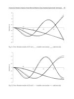
Fig. 7. Beam-like modes of vibration of clamped-free supported MWCNTs: (a) first bending,
(b) second bending, (c) first twisting, and (d) first axial modes.
For the clamped-free support condition, the basic mode shapes of vibration will be
described for a zigzag (5,0)-(14,0) double-walled CNT with length L = 15 nm and using a
higher aspect ratio than the previous example. Figure 7 correspondingly depicts modes that
are basic for large aspect ratios. Figures 7a and 7b illustrate the first and second bending
mode shapes. These are similar to the bending modes presented in a macro-scale cantilever
beam. The twisting modes (Figure 7c) exhibit a behavior similar to the clamped-clamped
case, but the shapes differ because of the free end. The first axial mode (Figure 7d) is
accompanied by a simultaneous movement of all atoms in the longitudinal direction and
changing tube length during the vibration.
4.3 Effect of layers on CNT vibration
In order to investigate the influence of the number of layers on the vibration characteristics
of a nanotube, CNTs of the same aspect ratio (i.e., the same length and outer diameter) were
chosen for analysis with the proposed technique. Figure 8a depicts how the natural
frequencies change for armchair tubes of length L = 17 nm and outer diameter D
o
= 2.45
nmwhen subjected to a clamped-clamped support condition. It is observed that the lower
the number of layers, the lower the frequency of the first radial breathing, second radial
breathing, first triangular, and first cross modes. In contrast, the higher the number of
layers, the lower the frequency of the first bending, second bending, first twisting, and first
axial modes. As the number of layers increases, the tube tends to behave more like a beam.
Note that for tubes with only one layer (single-walled CNTs), the basic modes are the first
triangular, the first cross, and the first radial breathing shapes. Figure 8b illustrates similar
variations for the clamped-free support condition. Here, the tube has length L = 15 nm and
outer diameter D
o
= 2.5 nm. In this case, the frequencies are certainly lower, as expected
with the less strict support condition. We also note that non-coaxial mode shapes are
revealed, together with modes for which the inner layers exhibit different shapes from the
outer ones. These are not analytically described because they are not basics modes of
vibration.
Advances in Vibration Analysis Research
130
1234
0.0
0.2
0.4
0.6
0.8
1.0
Natural Frequency (THz)
Number of Layers
1st Bending 2nd Bending
1st Radial 2nd Radial
1st Triangular 1st Cross
1st Twist 1st Axial
(a)
1234
0.0
0.2
0.4
0.6
0.8
Natural Frequency (THz)
Number of Layers
1st Bending 2nd Bending
1st Radial 2nd Radial
1st Triangular 1st Cross
1st Twist 1st Axial
(b)
Fig. 8. Natural frequencies of (a) a clamped-clamped armchair CNT (D
o
= 2.45nm,
L = 17nm), and (b) a clamped-free zigzag CNT (D
o
= 2.5nm, L = 15nm) vs number of layers.
An Atomistic-based Spring-mass Finite Element Approach for
Vibration Analysis of Carbon Nanotube Mass Detectors
131
012
10
5
10
6
10
7
10
8
10
9
10
10
10
11
10
12
Amplitude (nm)
Frequency (THz)
m / m
r
= 1
Pure CNT
(a)
012
10
5
10
6
10
7
10
8
10
9
10
10
10
11
10
12
m / m
r
= 10
Pure CNT
Amplitude (nm)
Frequency (THz)
(b)
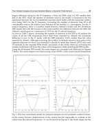
Fig. 9. Vibration spectra of clamped-free supported (5,0) CNT with a mass (a) m/m
r
= 1 and
(b) m/m
r
= 10 attached on the CNT tip.
Advances in Vibration Analysis Research
132
4.4 Vibration signature of CNT mass detectors
Also, the Fast Fourier Transform (FFT) of CNT mass detector is resembled for various cases
in order to be depicted the changes occurred in the spectrum due to the magnitude and
location of the added mass on CNT. In Figure 9, the spectra of a simply supported zigzag
(5,0) with and without an added mass equal to one (Figure 9(a)) or ten carbon atoms (Figure
9(b)) attached on the tip are illustrated. The length of the CNT is L = 10.95 nm. The
continuous red line gives the response of the CNT with the added mass, while the dashed
blue line gives the corresponding signature of the same, however, pure CNT.
Despite the very small value of the added mass, important changes are observed in
frequencies of the fundamental and higher order modes of vibration. Here, it has to be
noticed that, most of the available studies in the literature investigate mainly the
fundamental frequency shift. Nevertheless, significant changes in frequencies of higher
order modes are also obtained here, as in [34] also reported. The results demonstrate that the
higher order frequency shifts may be very helpful in the design and function of CNT mass
detectors. Similar results are obtained also for the case of clamped-clamped support
condition for the same CNT, when the added mass attached on the center of the CNT length
(Figure 10).
An important question, which should be answered before a practical CNT mass detector
may be made, is the problem of determining where the mass lands on the nanotube. Because
some parts of the tube vibrate much more than the base, a mass that lands near the fast-
moving region has a much greater effect on the resonant frequency and equivalent to a
much greater mass arriving near to the base. Moreover, in addition to the fundamental
mode of vibration, higher-order modes in which the maximum displacement occurs at two
or more positions along the nanotube are possible as have been previously seen. These
higher-order vibration modes could be exploited in experiments because the change in the
resonant frequency also depends on how much the nanotube moves at the absorbing point
[5]. This means that measurements made with higher-order modes could potentially allow
both the mass and landing position to be determined. In literature, the majority of
theoretical models are focused to sense the shift of the fundamental frequency due to an
added mass. However, this suffices to sense a mass addition to the CNT, but not to measure
the amount of mass because the magnitude of the shift is influenced by the mass and its
location on the CNT. Hence, the sensing and measurement of the mass require investigation
of the frequency shifts of the fundamental vibration mode as well as higher-order modes of
vibration [5,35]. Based on this concept, the spectra of the CNT-mass system for different
positions of the added mass on the CNT as well as different support conditions are depicted
in Figure 11 and Figure 12. Here, we assume a lager mass (m/m
r
= 100) than in previous
results. In all cases, there are a lot of additional modes of vibration in comparison with the
pure CNT case (see Figure 9). This can be explained by the asymmetry of the system
existing due to the large mass value. Extremely different behaviors for different mass
positions on CNT are observed in frequencies of the fundamental and higher order modes
of vibration.
The previous mentioned results demonstrate that CNTs reveal a very different vibration
signature even if a very small mass is added on its body. Moreover, they indicate that the
position of the added mass noticeably influences the CNTs vibration spectra. The present
methodology is capable to quantify these effects and thus can be used as a helpful
computational tool for the design of CNT mass detectors.
An Atomistic-based Spring-mass Finite Element Approach for
Vibration Analysis of Carbon Nanotube Mass Detectors
133
012
10
5
10
6
10
7
10
8
10
9
10
10
10
11
10
12
Amplitude (nm)
Frequency (THz)
m / m
r
= 1
Pure CNT
(a)
012
10
5
10
6
10
7
10
8
10
9
10
10
10
11
10
12
Amplitude (nm)
m / m
r
= 10
Pure CNT
Frequency (THz)
(b)
Fig. 10. Vibration spectra of clamped-clamped supported (5,0) CNT with a mass (a) m/m
r
= 1
and (b) m/m
r
= 10 attached on the middle of CNT length.