Heat Transfer Mathematical Modelling Numerical Methods and Information Technology Part 5 pptx
Bạn đang xem bản rút gọn của tài liệu. Xem và tải ngay bản đầy đủ của tài liệu tại đây (3.25 MB, 40 trang )
Finite Volume Method Analysis of Heat Transfer in
Multi-Block Grid During Solidification
21
in complex geometries, J. Mech. Sci. Tech., 19(9), 1773–1780.
Ni, J. & Beckermann, C. (1991). A volume-averaged two-phase model for transport
phenomena during solidification, Metall. Trans., 22B, 349–361.
Norris, S.E. (2001). A Parallel Navier Stokes Solver for Natural convection and Free Surface Flow,
Ph.D Thesis, Faculty of Mechanical Engineering, University of Sydney, Australia.
Pedroso, R.I. & Domoto, G.A. (1973). Inward spherical solidification-solution by the method
of strained coordinates, Int. J. Heat Mass Transf., 16, 1037-1043.
Peric, M. (1987). Efficient semi-implicit solving algorithm for nine-diagonal coefficient matrix,
Numer. Heat Transfer, 11(3), 251–279.
Pina, H. (1995). M´etodos Num´ericos, McGraw-Hill.
Radovic, Z. & Lalovic, M. (2005). Numerical simulation of steel ingot solidification process, J.
Mater. Process. Technol., 160, 156–159.
Rappaz, M. (1989). Modelling of microstructure formation in solidification processes, Int.
Mater. Rev., 34, 93–123.
Rappaz, M. & Voller, V. (1990). Modeling of micro-macrosegregation in solidification process,
Metal. Trans., 21A, 749–753.
Rouboa, A.; Monteiro, E. & Almeida, R. (2009). Finite volume method analysis of heat transfer
problem using adapted strongly implicit procedure, J. Mech. Sci. Tech., 23, 1–10.
Santos, C.A.; Spim, J.A. & Garcia, J.A. (2003). Mathematical modelling and optimization
strategies (genetic algorithm and knowledge base) applied to the continuous casting
of steel, Eng. Appl. Artif. Intelligence, 16, 511–527.
Schneider, G.E. & Zedan, M. (1981). A modified Strongly Implicit procedure for the numerical
solution of field problems, Numer. Heat Transfer, 4(1), 1–19.
Sciama, G. & Visconte, D. (1987). Mod´elisation des Transferts Thermiques Puor la Coul´ee
en Coquillede Pi`eces de Robinetterie Sanitaire, Foundarie, Fondeur d’Aujourd’hui, 70,
11–26.
Sethian, J.A. (1996). Level set methods and fast marching methods: evolving interfaces
in computational geometry, fluid mechanics, computer vision and materials science,
Cambridge University Press.
Shamsundar, N. & Sparrow, E.M. (1975). Analysis of multidimentional condution phase
change via the enthalpy model, J. Heat Transfer, 97, 333–340.
Shepel, S.E. & Paolucci, S. (2002). Numerical simulation of filling and solidification of
permanent mold casting, Applied Thermal Engineering, 22, 229–248.
Shi, Z. & Guo, Z.X. (2004). Numerical heat transfer modelling for wire casting, Mater. Sci.
Eng., A265, 311–317.
Stone, H.L. (1968). Iterative solution of implicit approximations of multidimensional partial
differential equations, SIAM, J. Numer. Anal., 5, 530–558.
Swaminathan, C.R. & Voller, V.R. (1997). Towards a general numerical scheme for
solidification systems, Int. J. Heat MassTransfer, 40, 2859 – 2868.
Tannehill, J.C.; Anderson, D.A. & Pletcher, R.H. (1997). Computational Fluid Mechanics and Heat
Transfer, 2nd edition, Taylor & Francis Ltd.
Thompson, J.F.; Warsi, Z.U.A. & Mastin, C.W. (1985). Numerical Grid Generation, Foundations
and Applications
, Elsevier Science Publishing Co., Amsterdam.
Tryggvason, G.; Esmaeeli, A. & Al-Rawahi, N. (2005). Direct numerical simulations of flows
with phase change, Computers & Structures, 83, 445–453.
Versteeg, H.K. & Malalasekera, W. (1995). An Introduction to Computational Fluid Dynamics: The
Finite Volume Method Approach, Prentice Hall.
149
Finite Volume Method Analysis of Heat Transfer in Multi-Block Grid During Solidification
22 Heat Transfer
Viskanta, R. (1990). Mathematical modeling of transport processes during solidification of
binary systems, JSME Int. J., 33, 409–423.
Voller,V. R.; Brent, A. D. & Prakash, C. (1989). The modelling of heat, mass and solute transport
in solidification systems, Int. J. Heat Mass Transfer, 32, 1719–1731.
Wang, G.X. & Matthys, E.F. (2002). Experimental ditermination of the interfacial heat transfer
during cooling and solidification of molten metal droplets impacting on a metallic
substrate: effect of roughness and superheat, Int. J. Heat Mass Transfer, 45, 4967–4981.
Wiwatanapataphee, B.; Wu, Y.H.; Archapitak, J.; Siew, P.F. & Unyong, B. (2004). A numerical
study of the turbulent flow of molten steel in a domain with a phase-change
boundary, Journal of Computational and Applied Mathematics, 166, 307–319.
150
Heat Transfer - Mathematical Modelling, Numerical Methods and Information Technology
6
Lattice Boltzmann Numerical Approach to
Predict Macroscale Thermal Fluid Flow Problem
Nor Azwadi Che Sidik and Syahrullail Samion
Universiti Teknologi Malaysia
Malaysia
1. Introduction
Flow in an enclosure driven by buoyancy force is a fundamental problem in fluid
mechanics. This type of flow is encountered in certain engineering applications within
electronic cooling technologies, in everyday situation such as roof ventilation or in academic
research where it may be used as a benchmark problem for testing newly developed
numerical methods. A classic example is the case where the flow is induced by differentially
heated walls of the cavity boundaries. Two vertical walls with constant hot and cold
temperature is the most well defined geometry and was studied extensively in the literature.
A comprehensive review was presented by Davis (1983). Other examples are the work by
Azwadi and Tanahashi (2006) and Tric (2000).
The analysis of flow and heat transfer in a differentially heated side walls was extended to
the inclusion of the inclination of the enclosure to the direction of gravity by Rasoul and
Prinos (1997). This study performed numerical investigations in two-dimensional thermal
fluid flows which are induced by the buoyancy force when the two facing sides of the cavity
are heated to different temperatures. The cavity was inclined at angles from 20° to 160°,
Rayleigh numbers from 10
3
to 10
6
and Prandtl numbers from 0.02 to 4000. Their results
indicated that the mean and local heat flux at the hot wall were significantly depend on the
inclination angle. They also found that this dependence becomes stronger for the inclination
angle greater than 90°.
Hart (1971) performed a theoretical and experimental study of thermal fluid flow in a
rectangular cavity at small aspect ratio and investigated the stability of the flow inside the
system. Ozoe et al. (1974) conducted numerical analysis using finite different method of
two-dimensional natural circulation in four types of rectangular cavity at inclination angles
from 0° to 180°. Kuyper et al. (1993) provided a wide range of numerical predictions of flow
in an inclined square cavity, covered from laminar to turbulent regions of the flow behavior.
They applied k -
ε
turbulence model and performed detailed analysis for Rayleigh numbers
of 10
6
to 10
10
.
A thorough search of the literature has revealed that no work has been reported for free
convection in an inclined square cavity with Neumann typed of boundary conditions. The
type of boundary condition applied on the bottom and top boundaries of the cavity strongly
affects the heat transfer mechanism in the system (Azwadi et al., 2010). Therefore, it is the
purpose of present study to investigate the fluid flow behaviour and heat transfer
mechanism in an inclined square cavity, differentially heated sidewalls and perfectly
conducting boundary condition for top and bottom walls.
Heat Transfer - Mathematical Modelling, Numerical Methods and Information Technology
152
The current study is summarized as follow: two dimensional fluid flow and heat transfer in
an inclined square cavity is investigated numerically. The two sidewalls are maintained at
different temperatures while the top and bottom walls are set as a perfectly conducting wall.
In current study, we fix the aspect ratio to unity. The flow structures and heat transfer
mechanism are highly dependent upon the inclination angle of the cavity. By also adopting
the Rayleigh number as a continuation parameter, the flow structure and heat transfers
mechanism represented by the streamlines and isotherms lines can be identified as function
of inclination angle. The computed average Nusselt number is also plotted to demonstrate
the effect of inclination angle on the thermal behaviour in the system. Section two of this
paper presents the governing equations for the case study in hand and introduces the
numerical method which will be adopted for its solution. Meanwhile section three presents
the computed results and provides a detailed discussion. The final section of this paper
concludes the current study.
2. Numerical formulation
In present research, the incompressible viscous fluid flow and heat transfer are studied in a
differentially heated side walls and perfectly conducting boundary conditions for top and
bottom walls. Then the square enclosure is inclined from 20° to 160° to investigate the effect
of inclination angles on thermal and fluid flow characteristics in the system. The governing
equations are solved indirectly: i. e. using the lattice Boltzmann mesoscale method (LBM)
with second order accuracy in space and time.
Our literature study found that there were several investigations have been conducted using
the LBM to understand the phenomenon of free convection in an enclosure (Azwadi &
Tanahashi, 2007; Azwadi & Tanahashi, 2008; Onishi et al., 2001). However, most of them
considered an enclosure at 90
0
inclination angle and adiabatic boundary conditions at top
and bottom walls. To the best of authors' knowledge, only Jami et al. (2006) predicted the
natural convection in an inclined enclosure at two Rayleigh numbers and two aspect ratios.
In their study, they investigated the fluid flow and heat transfer when an inclined partition
is attached to the hot wall enclosure and assumed adiabatic boundary condition at the top
and bottom walls. Due to lack of knowledge on the problem in hand, therefore, the objective
of present paper is to gain better understanding for the current case study by using the
lattice Boltzmann numerical method. To see this, we start with the evolution equations of
the density and temperature distribution functions, given as (He et al., 1998)
()
() () ()
(
)
1
,, ,,
eq
ii i i i
i
f
f
tt t f t f t f t F
τ
+
Δ+Δ− =− − +xc x x x
(1)
()
() () ()
(
)
1
,, ,,
eq
ii i i
i
g
gtttgt gtgt
τ
+Δ +Δ− =− −xc x x x
(2)
where the density distribution function
(
)
,
ff
t= x is used to calculate the density and
velocity fields and the temperature distribution function
(
)
,
gg
t= x is used to calculate the
macroscopic temperature field. Note that Bhatnagar-Gross-Krook (BGK) collision model
(Bhatnagar et al., 1954) with a single relaxation time is used for the collision term. For the
D2Q9 model (two-dimension nine-lattice velocity model), the discrete lattice velocities are
defined by
Lattice Boltzmann Numerical Approach to Predict Macroscale Thermal Fluid Flow Problem
153
(
)
()
()
()
()
()
()
()
()
()
()
0
0,0
cos 1 2 ,sin 1 2 , 1,2,3,4
2cos 5 2 4,sin 5 2 4, 5,6,7,8
i
i
ci i i
ci i i
ππ
ππ ππ
=
=− − =
=−+ −+=
c
c
c
(3)
Here, c is the lattice spacing. In LBM, the magnitude of
i
c is set up so that in each time step
t
Δ , the distribution function propagates in a distance of lattice nodes spacing xΔ . This will
ensure that the distribution function arrives exactly at the lattice nodes after t
Δ . The
equilibrium function for the density distribution function
e
q
i
f
for the D2Q9 model is given by
()
2
2
93
13
22
eq
ii i
i
f
ρω
⎡
⎤
=+⋅+⋅−
⎢
⎥
⎣
⎦
cu cu u
(4)
where the weights are
0
49
ω
=
, 19
i
ω
=
for i =1 - 4 and 136
i
ω
=
for i =5 - 8.
According to Azwadi and Tanahashi (2006) and He et al. (1998), the expression for
equilibrium function of temperature distribution can be written as
()
()
2
22 2
2
222
2
12
exp
22
42
2
2
D
eq
gT
RT RT DRT DRT D RT
DRT D DRT D RT
RT
ρ
π
⎡
⎧⎫ ⎛ ⎞
⋅
⎪⎪
⎛⎞
=−+−
⎢
⎜⎟
⎨⎬
⎜⎟
⎜⎟
⎝⎠
⎪⎪
⎢
⎩⎭ ⎝ ⎠
⎣
⎤
⎛⎞⎛⎞
⋅
⎥
−−−
⎜⎟⎜⎟
⎜⎟⎜⎟
⎥
⎝⎠⎝⎠
⎦
cc c cu
cu
ccu
(5)
Regroup Eq. (5) to avoid higher order quadrature gives
()
()
2
2
22
2
2
22
2
22
2
1
exp 1
22 2
2
1
exp 1
22
12
exp
22
4
D
eq
D
D
gT
RT RT RT RT
RT
T
RT RT DRT
D
T
RT RT DRT D RT
D
DRT D
ρ
π
ρ
π
ρ
π
⎡
⎤
⎧⎫
⋅
⋅
⎪⎪
⎛⎞
⎢
⎥
=
−++−+
⎨⎬
⎜⎟
⎝⎠ ⎢ ⎥
⎪⎪
⎩⎭
⎣
⎦
⎧⎫⎡ ⎤
⎪⎪
⎛⎞
−−+
⎢⎥
⎨⎬
⎜⎟
⎝⎠
⎢⎥
⎪⎪
⎩⎭⎣ ⎦
⎡
⎧⎫⎛ ⎞
+⋅
⎪⎪
⎛⎞
−−+
⎢
⎜⎟
⎨⎬
⎜⎟
⎜⎟
⎝⎠
⎪⎪
⎢
⎩⎭⎝ ⎠
⎣
⎛⎞
+
−
⎜⎟
⎜⎟
⎝⎠
cu
ccu u
cc
cc cu
c
c
()
()
2
22
2
2
2
2
i
D
DRT D RT
RT
⎤
⎛⎞
⋅
+
⎥
−−
⎜⎟
⎜⎟
⎥
⎝⎠
⎦
u
cu
(6)
It has been proved by Shi et al. (2004) that the zeroth through second order moments in the
last square bracket and the zeroth and first order moments in the second square bracket in
the right hand side of Eq. (6) vanish. The exclusion of the second order moments in the
second square bracket in Eq. (6) only related to the constant parameter in the thermal
conductivity which can be absorbed by manipulating the parameter
f
τ
in the computation.
Therefore, by dropping the terms in the last two square brackets on the right hand side of
Eq. (6) gives
()
()
2
2
22
2
1
exp 1
22 2
2
D
eq
gT
RT RT RT RT
RT
ρ
π
⎡
⎤
⎧⎫
⋅
⋅
⎪⎪
⎛⎞
⎢
⎥
=−++−
⎨⎬
⎜⎟
⎝⎠ ⎢ ⎥
⎪⎪
⎩⎭
⎣
⎦
cu
ccu u
(7)
Heat Transfer - Mathematical Modelling, Numerical Methods and Information Technology
154
After some modifications in order to satisfy the macroscopic energy equation via the
Chapmann-Enskog expansion procedure, the discretised equilibrium function for the
temperature distribution can be expressed as
()
2
2
93
13
22
eq
ii i
i
gT
ω
⎡
⎤
=+⋅+⋅−
⎢
⎥
⎣
⎦
cu cu u
(8)
where the weights are
0
49
ω
= , 19
i
ω
= for i =1 - 4 and 136
i
ω
= for i =5 - 8.
The macroscopic variables, density
ρ
, and temperature T can thus be evaluated as the
moment to the equilibrium distribution functions as
,
e
q
e
q
ii
ii
f
T
g
ρ
==
∑
∑
(9)
Through a multiscaling expansion, the mass and momentum equations can be derived for
D2Q9 model. The detail derivation of this is given by He and Luo (1997) and will not be
shown here. The kinematic viscosity of fluid is given by
21
6
f
τ
υ
−
= (10)
The energy equation at the macroscopic level can be expressed as follow
()
2
TT T
t
∂
ρ
ρχρ
∂
+∇⋅ = ∇u
(11)
where
χ
is the thermal diffusivity. Thermal diffusivity and the relaxation time of
temperature distribution function is related as
21
6
g
τ
χ
−
=
(12)
3. Problem physics and numerical results
The physical domain of the problem is represented in Fig. 1. The conventional no-slip
boundary conditions (Peng et al., 2003) are imposed on all the walls of the cavity. The
thermal conditions applied on the left and right walls are
T(x = 0, y) = T
H
and T(x = L, y) =
T
C
. The top and bottom walls being perfectly conducted,
(
)
(
)
HHC
TT xLT T=− − , where T
H
and
T
C
are hot and cold temperature, and L is the width of the enclosure. The temperature
difference between the left and right walls introduces a temperature gradient in a fluid, and
the consequent density difference induces a fluid motion, that is, convection.
The Boussinesq approximation is applied to the buoyancy force term. With this
approximation, it is assumed that all fluid properties can be considered as constant in the
body force term except for the temperature dependence of the density in the gravity term.
So the external force in Eq. (1) is
()
3
e
q
i
i
F
f
=−Gc u (13)
where
G is the contribution from buoyancy force.
Lattice Boltzmann Numerical Approach to Predict Macroscale Thermal Fluid Flow Problem
155
Fig. 1. Physical domain of the problem
The dynamical similarity depends on two dimensionless parameters: the Prandtl number Pr
and the Rayleigh number Ra,
3
0
Pr ,Ra
gTL
β
υ
χυχ
Δ
==
(14)
We carefully choose the characteristic speed
0c
vgLT=
so that the low-Mach-number
approximation is hold. Nusselt number, Nu is one of the most important dimensionless
numbers in describing the convective transport. The average Nusselt number in the system
is defined by
()
2
00
1
Nu , dxd
y
HH
x
H
qxy
T
H
χ
=
Δ
∫∫
(15)
where
(
)
(
)
(
)
(
)
,, ,
x
q
x
y
uT x
y
xTx
y
χ∂∂
=− is the local heat flux in x-direction.
In all simulations, Pr is set to be 7.0 to represent the circulation of water in the system.
Through the grid dependence study, the grid sizes of 251
× 251 is suitable for Rayleigh
numbers from 10
5
to 10
6
. The convergence criterion for all the tested cases is
() ()
11
1
22
22 22 7
Max 10
nn
uv uv
+
−
⎛⎞⎛⎞
+−+≤
⎜⎟⎜⎟
⎝⎠⎝⎠
(16)
17
Max 10
nn
TT
+
−
−≤
(17)
where the calculation is carried out over the entire system.
Streamlines and isotherms predicted for flows at Ra = 10
5
and different inclination angles
are shown in Figures 2 and 3. As can be seen from the figures of streamline plots, the liquid
near the hot wall is heated and goes up due to the buoyancy effect before it hits the corner
with the perfectly conducting walls and spread to a wide top wall. Then as it is cooled by
the cold wall, the liquid gets heavier and goes downwards to complete the cycle. At low value
of inclination angle, θ = 20, two small vortices are formed at the upper corner and lower corner
of the enclosure indicates high magnitude of flow velocity near these regions. The presence of
Heat Transfer - Mathematical Modelling, Numerical Methods and Information Technology
156
these two corner vortices compressed the central cell to form an elongated vortex. The
isotherms show a good mixing occurring in the center and relatively small gradient indicating
small value of the local Nusselt number along the differentially heated walls.
Fig. 2. Streamlines plots at Ra = 10
5
Lattice Boltzmann Numerical Approach to Predict Macroscale Thermal Fluid Flow Problem
157
Fig. 3. Isotherms plots at Ra = 10
5
.
Heat Transfer - Mathematical Modelling, Numerical Methods and Information Technology
158
Fig. 4. Streamlines plots at Ra = 5 × 10
5
.
Lattice Boltzmann Numerical Approach to Predict Macroscale Thermal Fluid Flow Problem
159
Fig. 5. Isotherms plots at Ra = 5 × 10
5
.
Heat Transfer - Mathematical Modelling, Numerical Methods and Information Technology
160
Fig. 6. Streamlines plots at Ra = 10
6
.
Lattice Boltzmann Numerical Approach to Predict Macroscale Thermal Fluid Flow Problem
161
Fig. 7. Isotherms plots at Ra = 10
6
.
Heat Transfer - Mathematical Modelling, Numerical Methods and Information Technology
162
Fig. 8. Effect of inclination angles on averaged Nusselt number
Further increment of inclination angle θ = 40° leads to the size reduction of small corner
vortices. At θ = 60°, the small corner vortices completely disappear and the central cell
pointing towards the corners because high magnitude of gravity vector drag the outer
vortex along the vertical walls of the enclosure. Denser isotherms lines can be seen from the
figure indicate higher value of local and average Nusselt number compared to previous
inclination angles. Further inclination of enclosure separates the main central vortex into
two smaller vortices. As we increase the inclination angle, these two vortices grow in size
indicates that some fluid from the hot or cold wall returns back to the same wall. For
inclination angles of θ = 80° to θ = 120°, the isotherms line are parallel to the perfectly
conducting walls indicates that the main heat transfer mechanism is by convection. Denser
isotherms lines can be seen near the bottom left and top right corners demonstrate high local
Nusselt number near these regions. However, at high inclination angles, θ ≥ 140°, the
isotherms lines are equally spaced indicates low averages Nusselt number in the system.
For Rayleigh number equals to 5×10
5
and low inclination angles, the central vortex is more
rounded indicates equal magnitude of flow velocity near all four enclosure walls. At angle
equals to θ = 60°, the central cells splits into two before the corner vortices disappear. The
velocity boundary layer can be clearly seen for inclination angles of θ = 60° and above. The
isotherm patterns are similar to those for Ra = 10
5
at all angles. However, the thermal
boundary layers are thicker indicating higher local and average Nusselt number along the
cold and hot walls.
For the simulation at the highest Rayleigh number in the present study Ra = 10
6
, the
formation of corner vortices can be clearly seen at low value of inclination angles. At angle
equals to θ = 20°, the complex structure of upper corner vortices indicates the instability of
the flow in the system. This flow instability is confirmed when we were unable to obtain a
steady solution even for a very high iteration number. The isotherms plots also display a
complex thermal behavior and good mixing of temperature in the system. The flow becomes
steady again when we increase the inclination angle to θ = 60°. The central vortex is
separated into two smaller vortices and vertically elongated shaped indicates relatively high
Lattice Boltzmann Numerical Approach to Predict Macroscale Thermal Fluid Flow Problem
163
value of flow velocity near the differentially heated walls. Most of the isotherms lines
becomes parallel to the perfectly conducting walls indicates the convection type dominates
the heat transfer mechanism in the system.
For θ > 80°, the central vortex is stretched from corner to corner of the enclosure and
perpendicular to the gravitational vector, developed denser streamlines near these corners,
indicating the position of maximum flow velocity for the current condition. On the other
hand, similar features of isotherms to those at lower Ra are observed.
The effect of the inclination angle on the average Nusselt number is shown in Figure 8 for all
values of Rayleigh numbers. One common characteristic which can be drawn from the
figure; the Nusselt number increases with increasing the Rayleigh number. However, the
computed Nusselt numbers are lower than those for the case of adiabatic types of boundary
condition (Peng et al., 2003) because the heat is allowed to pass through the top and bottom
walls. Interestingly, the minimum value of average Nusselt number is found converging to
the same value and when the inclination angle approaching θ = 180° for every Rayleigh
number. On the other hand, the maximum value of average Nusselt number is determined
at inclination angle between θ = 60° to θ = 80°. These can be explained by analyzing the
isotherms plots which demonstrating relatively denser lines near hot and cold walls leading
to high temperature gradient near these regions. Lower value of average Nusselt number at
lower inclination angle was due to the presence of small corner vortices which contributes
smaller local heat transfer along the hot and cold walls. For the computation at higher
inclination angles, where the hot wall is close to the top position, the magnitude of the
gravity vector is reduced results in low magnitude of flow velocity along the hot wall. Due
to this reason, the heat transfer rates are small resulted from the reduction in the driving
potential for free convection.
4. Conclusion
The free convection in an inclined cavity has been simulated using the mesoscale numerical
scheme where the Navier Stokes equation was solved indirectly using the lattice Boltzmann
method. The result of streamlines plots clearly depicting the flow pattern and vortex
structure in the cavity. The primary vortex is transformed from a single cellular to a double
cellular as the inclination angle increases. These demonstrate the lattice Boltzmann
numerical scheme of passive-scalar thermal lattice Boltzmann model is a very efficient
numerical method to study flow and heat transfer in a differentially heated inclined
enclosure.
5. Acknowledgement
The authors would like to acknowledge Universiti Teknologi Malaysia and Malaysia
Government for supporting these research activities. This research is supported by research
grant No. 78604
6. References
Bhatnagar, P. L.; Gross, E. P. & Krook, M. (1954). A Model for Collision Process in Gases. 1.
Small Amplitude Processes in Charged and Neutral One-Component System,
Physical Review, Vol. 94, No. 3, 511-525.
Heat Transfer - Mathematical Modelling, Numerical Methods and Information Technology
164
Davis, D. V. (1983). Natural Convection of Air in a Square Cavity; A Benchmark Numerical
Solution, International Journal for Numerical Methods in Fluids, Vol. 3, No. 3, 249-264,
ISSN 1097-0363.
Hart, J. E. (1971). Stability of the Flow in a Differentially Heated Inclined Box, Journal of Fluid
Mechanics, Vol. 47, No. 3, 547-576, ISSN 0022-1120.
He, X. & Luo, L. S. (1997). Lattice Boltzmann Model for the Incompressible Navier-Stokes
Equation, Journal of Statistical Physics, Vol. 88, No. 3, 927-944, ISSN 0022-4715.
He, X.; Shan, S. & Doolen, G. (1998). A Novel Thermal Model for Lattice Boltzmann Method
in Incompressible Limit, Journal of Computational Physics, Vol. 146, No. 1, 282-300,
ISSN 0021-9991.
Jami, M.; Mezrhab, A.; Bouzidi, M. & Lallemand, P. (2006). Lattice-Boltzmann Computation
of Natural Convection in a Partitioned Enclosure with Inclined Partitions Attached
to its Hot Wall, Physica A, Vol. 368, No. 2, 481-494.
Kuyper, R. A.; Meer, V. D.; Hoogendoorn, C. J. & Henkes, R. A. W. (1993). Numerical Study of
Laminar and Turbulent Natural Convection in an Inclined Square Cavity,
International Journal of Heat Mass Transfer, Vol. 36, No. 11, 2899-2911, ISSN 0017-9310.
Nor Azwadi, C. S. & Tanahashi, T. (2006). Simplified Thermal Lattice Boltzmann in
Incompressible Limit, International Journal of Modern Physics B, Vol. 20, No. 17, 2437-
2449, ISSN 0217-9792.
Nor Azwadi, C. S. & Tanahashi, T. (2007). Three-Dimensional Thermal Lattice Boltzmann
Simulation of Natural Convection in a Cubic Cavity, International Journal of Modern
Physics B, Vol. 21, No. 1, 87-96, ISSN 0217-9792.
Nor Azwadi, C. S. & Tanahashi, T. (2008). Simplified Finite Difference Thermal Lattice
Boltzmann Method, International Journal of Modern Physics B, Vol. 22, No. 22, 3865-
3876, ISSN 0217-9792.
Nor Azwadi, C. S.; Mohd Fairus, M. Y. & Samion, S. (2010). Virtual Study of Natural
Convection Heat Transfer in an Inclined Square Cavity, Journal of Applied Sciences,
Vol. 10, No. 4, 331-336, ISSN 1812-5654.
Onishi, J.; Chen, Y. & Ohashi, H. (2001). Lattice Boltzmann Simulation of Natural Convection
in a Square Cavity, JSME International Journal Series B, Vol. 44, No. 1, 53-62.
Ozoe, H.; Yamamoto, K.; Sagama, H. & Churchill, S. W. (1974). Natural Circulation in an
Inclined Rectangular Channel Heated on One Side and Cooled on the Opposing
Side, International Journal of Heat Mass Transfer, Vol. 17, No. 10, 1209-1217, ISSN
0017-9310.
Peng, Y.; Shu, C. & Chew, Y. T. (2003). Simplified thermal lattice Boltzmann model for
incompressible thermal flows, Physical Review E, Vol. 68, No. 1, 020671/1-20671/8,
ISSN 1539-3755.
Rasoul, J. & Prinos, P. (1997). Natural Convection in an Inclined Enclosure, International
Journal of Numerical Methods for Heat and Fluid Flow, Vol. 7, No. 5, 438-478, ISSN
0961-5539.
Shi, Y.; Zhao, T. S. & Guo, Z. L. (2004). Thermal lattice Bhatnagar-Gross-Krook model for
flows with viscous heat dissipation in the incompressible limit, Physical Review E,
Vol. 70, No. 6, 066310/1-066310/10, ISSN 1539-3755.
Tric, E.; Labrosse, G. & Betrouni, M. (2000). A First Incursion into the 3D Structure of
Natural Convection of Air in a Differentially Heated Cubic Cavity, from Accurate
Numerical Solutions, International Journal of Heat and Mass Transfer, Vol. 43, No. 21,
4043-4056, ISSN 0017-9310
0
Efficient Simulation of Transient HeatyTransfer
Problems in Civil Engineering
Sebastian Bindick, Benjamin Ahrenholz, Manfred Krafczyk
Institute for Computational Modeling in Civil Engineering, Technische Universitet
Braunschweig
Germany
1. Introduction
Heat transport problems arise in many fields of civil engineering e.g. indoor climate comfort,
building insulation, HVAC (heating, ventilating, and air conditioning) or fire prevention to
name a few. An a priori and precise knowledge of the thermal behavior is indispensable
for an efficient optimization and planning process. The complex space-time behavior of
heat transfer in 3D domains can only be achieved with extensive computer simulations (or
prohibitively complex experiments). In this article we describe approaches to simulate the
transient coupled modes of heat transfer (convection, conduction and radiation) applicable
to many fields in civil engineering. The numerical simulation of these coupled multi-scale,
multi-physics problems are still very challenging and require great care in modeling the
different spatio-temporal scales of the problem. One approach in this direction is offered by
the Lattice-Boltzmann method (LBM) which is known to be a viable Ansatz for simulating
physically complex problems. For the simulation of radiation a radiosity method is used
which also has already proven its suitability for modeling radiation based heat transfer. The
coupling and some typical applications of both methods are discussed in this chapter.
2. Modeling thermal flows with Lattice-Boltzmann
In the last two decades the Lattice-Boltzmann-Methods (LBM) has matured as an efficient
alternative to discretizing macroscopic transport equations such as the Navier-Stokes
equations describing coupled transport problems such as thermal flows. The Boltzmann
equation describes the dynamics of a propability distribution function of particles with
a microscopic particle velocity under the influence of a collision operator. Macroscopic
quantities such as the fields of density, flow velocities, energy or heat fluxes are consistently
computed as moments of ascending order from the solution. For flow problems the Boltzmann
equation can be drastically simplified by discretizing the microscopic velocity space and by
using a simplified collision operator. A non-trivial yet algorithmically straight forward Finite
Difference discretization for this set of PDEs results in the Lattice-Boltzmann equations. For
the simulation of thermal driven flows using the LB method a hybrid thermal LB model
(Hybrid TLBE) has been established, i.e. an explicit coupling between an athermal LBE
scheme for the flow part and a separate Lattice-Boltzmann equation for the temperature
equation.
7
2 Heat Transfer
2.1 An overview of the physical background of lattice Boltzmann models
The origin of the physical modeling process is the fact that the physical scope of validity of
the Boltzmann equation includes the Navier-Stokes equations as well. In the framework of the
kinetic gas theory it can be shown that the Navier-Stokes equations can be derived from the
Boltzmann equation in the limit of small Knudsen numbers if the hydrodynamic momentum
and pressure fields are described as low order moments of the primary variables of the
Boltzmann equation (i.e. probability distributions). This implies that approximate solutions
of the Boltzmann equations and their resulting moments can be used to calculate approximate
solutions for the corresponding Navier-Stokes equations (Succi, 2001; He & Luo, 1997b;
Bhatnagar et al., 1954). A direct discretization of the full Boltzmann equation is neither useful
nor necessary for most macroscopic flow problems; therefore, the following simplifications are
typically made: First, the collision operator in the so-called BGK or Multiple-Relaxation-Time
(MRT) approximation is considered, which assumes that the particle system is statistically
close to a kinetic equilibrium. Furthermore, the microscopic velocity space is discretized
to develop a system of discrete Boltzmann equations, instead of the Boltzmann equation in
BGK-approximation. These discrete equations contain a constant prefactor in the convective
term, which suggests a discretization along the corresponding characteristics. This system of
discrete Boltzmann equations can be numerically discretized in different ways. The model
relationships are outlined in Figure 1.
Historically, LBM originated from the lattice gas automata [LGA], which can be considered as
a simplified, fictitious molecular dynamics in which space, time, and particle velocities are all
discrete. However, it was discovered that LGA suffers from several inherent defects including
Chapman-Enskog expansion
Chapman-Enskog-Expansion
small Knudsen number
Bhatnagar-Gross-Krook-Approximation (BGK)
Discretization in space and time
small Knudsen number
small Mach number
Discretization in velocity space
mass continuity equation
@
u
@t
+(
u
5)
u
= ¡
1
½
5 p +
´
½
¢
u
Navier-Stokes equations:
5u =0
Boltzmann equation
@f
i
@t
+
e
i
@f
i
@
x
= ¡
1
¿
³
f
i
¡ f
eq
i
´
discrete Boltzmann equation
f
i
(t+¢t;
x
+
e
i
¢t)=f
i
(t;
x
)¡
¢t
¿
³
f
i
(t;
x
)¡f
eq
i
(t;
x
)
´
@f
@t
+
»
@f
@
x
= ¡
1
¿
³
f ¡ f
eq
´
simplified Boltzmann equation
Ω
@f
@t
+
»
@f
@
x
=(f; f
0
)
Lattice Boltzmann equation
impulse transport equation
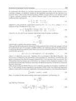
Fig. 1. From the Boltzmann equation to Navier-Stokes
166
Heat Transfer - Mathematical Modelling, Numerical Methods and Information Technology
Efficient Simulation of Transient HeatyTransfer Problems in Civil Engineering 3
the lack of Galilean invariance (except for ρ = constant), the presence of statistical noise and
the absence of exponential complexity for three-dimensional lattices. The main motivation
for the transition from LGA to LBM was the desire to remove statistical noise by replacing
the Boolean particle number in a lattice direction with its ensemble average, the so-called
density distribution function. Accompanying this replacement, the discrete collision rules
also have to be modified as a continuous function - the collision operator. The first LBM has
been proposed by (McNamara & Zanetti, 1988) and improved by (Higuera & Jim
´
enez, 1989;
Higuera et al., 1989). However, the connection to the Boltzmann equation (introduced by the
Austrian physicist Ludwig Boltzmann in 1872) has been proven afterwards (He & Luo, 1997b;
Sterling & Chen, 1996). The Boltzmann equation describes the statistical distribution of one
particle in a fluid and the probability to encounter this particle at time t with velocity ξ
ξ
ξ at
location x (Cercignani et al., 1994; Cercignani & Penrose, 1998):
∂ f
∂t
+ ξ
ξ
ξ ·
∂ f
∂x
+ F ·
∂ f
∂ξ
ξ
ξ
= Ω( f, f
) (1)
In the LBM development, an important simplification is the approximation of the collision
operator with the Bhatnagar-Gross-Krook (BGK) relaxation term. This lattice BGK (LBGK)
model renders simulations more efficient and allows flexibility of the transport coefficients.
On the other hand, it has been shown that the LBM scheme can also be considered as a
special discretized form of the continuous Boltzmann equation. Through a Chapman-Enskog
expansion (Frisch et al., 1987; Qian et al., 1992) or an asymptotic analysis (Junk et al., 2005),
one can recover the governing continuity and Navier-Stokes equations (Equation 2) from the
LBM algorithm (Qian et al., 1992).
∂u
∂t
+(u∇)u = −
1
ρ
∇p +
μ
ρ
Δu, (2a)
∇u = 0 (2b)
In addition, the pressure field is also directly available from the density distributions as p
=
c
2
S
ρ where c
s
is the speed of sound and hence there is no additional Poisson equation to be
solved as in traditional CFD methods.
A particularly effective form of discretization is obtained if the spatial grid is being chosen
so that the advection of the distribution functions follows exactly the characteristics defined
by the microscopic particle velocities, i.e. if the physical discretization of the microscopic
velocity space (after multiplying it with the appropriate local time step) is congruent with the
numerical grid. This leads to a relatively simple Finite-difference approach. With the help of
an appropriate multi-scale expansion it can be shown that the moments of zero to second
order are approximate solutions of the velocity and pressure tensor of the Navier-Stokes
equations, given that the relaxation time included in the BGK-operator is defined as a linear
function of the kinematic viscosity. Yet, this scheme would not be competitive without
further modifications. Theoretical analysis allows to determine a global constant numerical
viscosity, which can be eliminated by appropriate scaling, resulting in a method of quadratic
accuracy in space for the Navier-Stokes equations. A detailed description of the underlying
derivations can be found in (Qian et al., 1992; Chen & Doolen, 1998; Succi, 2001; Dellar,
2003; He & Luo, 1997a;b; Bhatnagar et al., 1954) The accuracy of the method in the fluid
depends, like for all transport problems mainly on the quality of the boundary conditions.
In contrast to the direct discretization of the Navier-Stokes equations corresponding initial-
and boundary conditions must be specified for the probability distributions within LBM.
167
Efficient Simulation of Transient Heat Transfer Problems in Civil Engineering
4 Heat Transfer
Different approaches have been developed regarding accuracy and consistency and have been
analyzed in the corresponding literature see e.g. (Junk et al., 2005; Ginzburg & d’Humi
`
eres,
1996; d’Humi
`
eres et al., 2002). Since typical LBM discretizations are based on Cartesian
grids, it represents a curved surface only with first order accuracy. For second order accurate
fluid/wall boundary conditions it is necessary to compute the projection of the node links
to the surface of the geometry and incorporate them into the discretization scheme for the
boundary conditions. If MRT approaches (d’Humi
`
eres et al., 2002) are used, boundary
conditions for pressure and velocities can be enforced with second order accuracy. The
application of hierarchical Cartesian grid allows the use of tree type data structures and
enables a hierarchical time-step procedure with an optimal Courant number of one at each
grid level, i.e. on coarse grid cells only a correspondingly coarser time step is necessary ( Tlke
et al., 2006). The issue of efficiency of the LB method in direct comparison with state-of-the-art
FE and FV-discretizations of the Navier-Stokes equations is discussed e.g. in (Geller et al.,
2006).
Unlike the traditional computational fluid dynamics (CFD), which numerically solves the
conservation equations of macroscopic properties (i. e., mass, momentum, and energy), LBM
models the fluid consisting of fictitious particles, which perform consecutive propagation and
collision processes over a discrete lattice. Due to its particulate nature and local dynamics,
LBM is very efficient when dealing with complex boundaries and the incorporation of
microscopic interactions.
2.2 A short introduction to the lattice Boltzmann method
The LB method is a numerical method to solve the Navier-Stokes equations Frisch et al.
(1987); Benzi et al. (1992); Chen & Doolen (1998), where density distributions propagate and
collide on a regular lattice. A common labeling for different lattice Boltzmann models is
DdQq (Qian et al., 1992), where d is the space dimension and q the number of microscopic
velocities. Besides the most common D3Q19 models (Figure 2) one can often find D3Q15
stencils (Figure 2) in 3D and D2Q9 in 2D (Figure 3) as well as non local stencils like D3Q27
or D3Q39. D3Q13 uses a reduced set of velocities, however it is very promising due to an
excellent ratio between accuracy and computational requirements (d’Humi
`
eres et al., 2001;
Tlke & Krafczyk, 2008).
In the following section x represents a 3D vector in space and f
f
f a b-dimensional vector, where
East
Bottom
North
TopNorthEast
Top
South
West
TopNorthEast
TopSouthEast
TopNorthWest
BottomNorthWest
TopSouthWest
BottomSouthWest
BottomSouthEast
NorthEast
Bottom
BottomEast
BottomNorth
South
North
Top
TopWest
TopNorth
TopEast
East
SouthEast
BottomWest
BottomSouth
NorthWest
TopSouth
West
SouthWest
Fig. 2. D3Q19- and D3Q15 stencils, the most common representatives in 3D
168
Heat Transfer - Mathematical Modelling, Numerical Methods and Information Technology
Efficient Simulation of Transient HeatyTransfer Problems in Civil Engineering 5
West East
NorthEastNorthWest North
South SouthEastSouthWest
Zero
Fig. 3. D2Q9 stencil commonly used for 2D LBM and D3Q13 - the smallest stencil for a space
filling grid in 3D
b is the number of microscopic velocities. The 19 velocities are given as
e
i
,i = 0, ,18} =
⎛
⎝
0 c
−c 0000c −cc−cc−cc−c 0000
00 0c
−c 00c −c −cc0000c −cc−c
00 00 0c
−c 0000c −c −ccc−c −cc
⎞
⎠
where c is a constant microscopic reference velocity related to the speed of sound by c
2
s
=
c
2
/3. The microscopic velocities define a space-filling computational lattice where a node is
connected to the neighboring nodes through the vectors
{
Δt e
i
,i = 0, ,18
}
. The generalized
lattice Boltzmann equation (GLBE) using the Multiple-Relaxation-Time model introduced by
(d’Humi
`
eres, 1992; Lallemand & Luo, 2000) is given by
f
i
(t + Δt, x + e
i
Δt)= f
i
(t,x)+Ω
i
, i = 0, ,b − 1, (3)
where f
i
are mass fractions (unit kg m
−3
) propagating with velocities e
i
, Δt is the time step,
the grid spacing is Δx
= cΔt , and the collision operator of the Multiple-Relaxation-Time model
(MRT) is given by
Ω
= M
−1
S
((
M f
f
f
)
−
m
m
m
eq
)
. (4)
The matrix M is used to transform the distributions into moment space. The resulting
moments m
m
m
= M f
f
f are labeled as
m
m
m
=(δρ,e,, j
x
,q
x
, j
y
,q
y
, j
z
,q
z
,3p
xx
,3π
xx
, p
ww
,π
ww
, p
xy
, p
yz
, p
xz
,m
x
,m
y
,m
z
),
where δρ is a density variation related to the pressure variation δp by
δp
=
c
2
3
δρ. (5)
and where
(j
x
, j
y
, j
z
)=ρ
0
(u
x
,u
y
,u
z
) is the momentum and ρ
0
is a constant reference
density. The moments e, p
xx
, p
ww
, p
xy
, p
yz
, p
xz
of second order are related to the stress tensor
(Equation 6). The other moments of higher order are related to higher order derivatives of the
flow field and have no direct physical impact with respect to the incompressible Navier-Stokes
equations.
169
Efficient Simulation of Transient Heat Transfer Problems in Civil Engineering
6 Heat Transfer
σ
αβ
= −pδ
αβ
+ ρν(
∂u
α
∂x
β
+
∂u
β
∂x
α
) (6)
The matrix S is a diagonal collision matrix composed of relaxation rates
{s
i,i
, ,b −1}, also
called the eigenvalues of the collision matrix M
−1
SM. The rates different from zero are
s
1,1
= −s
e
s
2,2
= −s
s
4,4
= s
6,6
= s
8,8
= −s
q
s
10,10
= s
12,12
= −s
π
s
9,9
= s
11,11
= s
13,13
= s
14,14
= s
15,15
= −s
ν
s
16,16
= s
17,17
= s
18,18
= −s
m
.
The relaxation rate s
ν
is related to the kinematic viscosity ν by
s
ν
=
1
3
ν
c
2
Δt
+
1
2
. (7)
The remaining relaxation rates s
e
,s
,s
q
,s
π
and s
m
can be freely chosen in the range of [0, 2] and
may be tuned to improve accuracy as well as stability (Lallemand & Luo, 2000) of the model.
The optimum values depend on the specific system under consideration (geometry, initial,
and boundary conditions) and can therefore not be computed in advance for general cases.
In summary it may be noted that if one uses either a Chapman-Enskog expansion (Frisch
et al., 1987) or an asymptotic expansion using the diffusive scaling (Junk et al., 2005), it can be
shown that the lattice Boltzmann method is a scheme of first order in time and second order
in space for the incompressible Navier-Stokes equations.
2.3 Thermal flows
During the last decade different approaches for the simulation of thermal driven flows using
the LB method have been developed (Alexander et al., 1993; Vahala et al., 2000; Shan, 1997;
Qian, 1993; Filippova & H
¨
anel, 2000; Lallemand & Luo, 2003). Energy conserving thermal
LB equation models (TLBE) use a larger set of discrete velocities than the standard method
(Qian et al., 1992) to include a thermal variable, such as temperature. The internal energy is
defined by a second-order moment of the distribution function, and the collision operator is
chosen to satisfy local energy conservation. However, these thermal flow simulations utilizing
the thermal lattice Boltzmann equation (TLBE) are hampered by numerical instabilities
caused by an algebraic coupling among different modes of the linearized collision operator,
independently of the number of discrete velocities used in the model (Lallemand & Luo, 2003).
To avoid the limitations of TLBE a hybrid scheme was developed in (Lallemand & Luo, 2003)
by coupling the energy mode of the athermal LB model to the temperature field. This method
has been extended for turbulent flows by (van Treeck et al., 2006) and is usually referred to as
hybrid thermal lattice Boltzmann equation (HTLBE).
In this work the temperature equation is discretized by the following finite difference (FD)
scheme:
T
i,j,k
(t + Δt
FD
) −T
i,j,k
(t)
Δt
FD
= −
j
i,j,k
(t)∇
(h)
i,j,k
T
i,j,k
(t)+α
(h)
i,j,k
T
i,j,k
(t) (8)
170
Heat Transfer - Mathematical Modelling, Numerical Methods and Information Technology
Efficient Simulation of Transient HeatyTransfer Problems in Civil Engineering 7
where α is the thermal diffusivity. For computing the difference operators ∇
(h)
i,j,k
and
(h)
i,j,k
a 6 point stencil is used. The coupling of both schemes is explicit, meaning that the velocity
field obtained by the MRT scheme is inserted into the energy equation while the solution of the
latter is used to compute the buoyant force F
z
(
x, t) in the sense of a Boussinesq approximation.
For a given Rayleigh number
Ra
=
Prg
z
βΔTL
3
ν
2
(9)
and Prandtl number Pr
= ν/α and by setting β = 1/T
0
, the parameters viscosity ν and
diffusivity α are obtained and the relaxation coefficients can be determined with the formulae
given in (Lallemand & Luo, 2003), while ν has to fulfill the stability constraints of the MRT
scheme. L is a characteristic length scale of the dimensionless system, i.e. given in lattice
units. The coupling of the temperature field to the energy mode of the LB model is done by
inserting the temperature into the equilibrium moments (Tlke, 2006):
m
eq
1
=((3T − 1)+(u
2
x
+ u
2
y
+ u
2
z
))ρ
0
(10)
m
eq
2
=(1 −1.8T)ρ
0
(11)
where T
= T(t, i, j,k) is a dimensionless temperature varying in space and time.
In order to simulate more realistic engineering applications, such as convective heat transport
in buildings, simulations with Reynolds numbers of more than 10
6
have to be performed.
At this scale DNS simulations become too expensive and therefore it is necessary to extend
the standard HTLBE by a turbulence model. Large-eddy (LES) approaches are regarded as a
promising compromise between explicit modeling of all scales of the turbulent spectrum and
direct numerical simulation (DNS). In LES the large scale motions of the flow are calculated,
while the effect of the smaller universal scales (the so called sub-grid scales) are modeled
using a sub-grid scale (SGS) model. The most commonly used SGS model is the Smagorinsky
model. It compensates for the unresolved turbulent scales through the addition of a so-called
eddy viscosity into the governing equations.
In the context of lattice Boltzmann, the LES approach has first been used by (Hou et al.,
1994) in 2D and in (Krafczyk et al., 2003) in 3D. As an inherent property of the LBE scheme,
components of the momentum flux tensor, here expressed in terms of moments,
Π
αβ
=
∑
i
e
iα
e
iβ
f
i
(12)
are given as local quantities and do not have to be computed from derivatives of
hydrodynamic quantities. Therefore, the local strain tensor is obtained by the relation
˜
αβ
=
s
xx
2ρC
2
s
(C
2
s
ρδ
αβ
+ ρu
α
u
β
−Π
αβ
) (13)
as previously shown by (Krafczyk et al., 2003). Consequently, the molecular and turbulent
viscosities can be added to form a total viscosity ν
total
= ν
0
+ ν
T
which substitutes the material
property by a space and time-dependent quantity. Having computed a local value for ν
T
, the
relaxation parameter s
xx
for the second order moments related to the stress tensor components
p
xx
, p
ww
, p
xy
, p
yz
and p
zx
can be determined by
171
Efficient Simulation of Transient Heat Transfer Problems in Civil Engineering
8 Heat Transfer
s
xx
=
1
3(ν
0
+ ν
T
)+
1
2
, (14)
where ν
T
is either related to the same time step or the last time step before propagation of
the explicit scheme. Due to consistency reasons a subgrid model is also used for heat flux as
proposed in (van Treeck et al., 2006).
3. Radiative heat transfer using the Radiosity-method
In this section an approach for radiative heat transfer in 3d domains based on the hierarchical
radiosity method coupled to the LB method is presented. The radiosity method assumes
radiative exchange between gray, diffuse surfaces in a radiatively non-participating medium.
The idea is to hierarchically subdivide surfaces forming a quad-tree structure until a
refinement criterion is reached. The fundamental underlying operation of the radiosity
method is visibility detection which can be solved efficiently by using a space partitioning
approach for the input surfaces. For this reason a kd-tree is chosen which is the most
efficient method for visibility detection on irregularly distributed surfaces. These approaches
dramatically decrease the complexity of the radiation problem from O
(n
3
) to O((k
2
+ n) log k),
where k is the number of input surfaces and n is the number of refined surfaces. For
validations of these approach for several non-trivial examples, demonstrating that this scheme
is second-order accurate see (Bindick et al., 2010).
3.1 Modeling radiative heat transfer
Heat flux from a body induced by thermal radiation solely depends on the local surface
temperature and is not bound to molecular transport. This implies that every body is not
only interacting with its direct neighbors but with all visible elements. Thermal radiation
incident to a surface may be partially absorbed, reflected or transmitted. Here the absorbed
part will be transformed into thermal energy. The complex radiative processes at a solid body
are depicted in Fig.4.
The energy flux M
(λ, T) emitted from a surface with the temperature T and the wavelength
λ can be described through the Planck’s law of black-body radiation:
Fig. 4. Radiative processes at a solid body
172
Heat Transfer - Mathematical Modelling, Numerical Methods and Information Technology
Efficient Simulation of Transient HeatyTransfer Problems in Civil Engineering 9
M(λ, T)=
2πc
2
0
h
4
A
e
(hc
0
/kλT)
−1
dλ
[W], (15)
with the Planck constant h
= 6,626 ·10
−34
J ·s, the speed of light c
0
and the Boltzmann constant
k
= 1,381 ·10
−23
J/K. This energy distribution is not constant over the spectrum and rises with
increasing wavelength until a maximum at λ
max
is reached (Siegel & Howell, 2002).
The energy flux leaving or entering a body depending on the direction in space can be
described by the irradiance (E), the radiant energy arriving at a surface:
E
=
Ω
I
a
cos(Θ) dΩ
W
m
2
(16)
with the radiative intensity I
a
depending on the wavelength and cos(Θ) dΩ representing
the projection of the solid angle. Analogously, the radiosity B (the radiant energy leaving
a surface) can be written as:
B
=
Ω
I
l
cos(Θ) dΩ
W
m
2
. (17)
In the following sections we describe how to solve the corresponding equations for a full
radiant energy exchange in an enclosed 3d domain using the radiosity method (Goral et al.,
1984).
The fundamentals of radiative heat transfer are explained in detail in e.g. (Siegel & Howell,
2002), (Modest, 2003), (Baehr & Stephan, 2006) and (Welty et al., 2001).
3.2 The classical radiosity method
The full energy exchange between diffuse surfaces can be calculated by forming an energy
equilibrium for Eq. (16) and Eq. (17) in an enclosed environment. This approach leads
to the radiosity method (based on the zonal method (Hottel & Cohen, 1958)) often used in
the field of computer graphics to compute the inter-reflections of light (global illumination)
(Goral et al., 1984). The radiosity method has long been an active field of research and many
improvements could be found to reduce the algorithmic complexity of the problem. The
radiosity method comes with the assumption that all bodies are gray diffusive reflectors,
emitters and absorbers, (i.e. the same amount of radiant energy is reflected, emitted and
absorbed in all directions) which is a common approximations for real bodies. Another
assumption is that the radiative heat transfer between surfaces is separated by vacuum
(radiatively nonparticipating), without considering the absorbing, scattering and emitting
effects of the medium. This is a common approach for the relatively low pressures and
temperatures that occur in many engineering applications. By subdividing the geometry
surfaces into small planar patches, with homogeneous material properties, the discrete
radiosity equation can be written as the sum of the patch radiation E
i
and the radiosity B
j
of all other n patches multiplied with the diffuse reflectivity ρ
d
:
B
i
= E
i
+ ρ
d
n
∑
j=1
B
j
F
ij
, (18)
with the configuration factor F
ij
depending on the geometrical relation between two patches
(see Fig.5).
173
Efficient Simulation of Transient Heat Transfer Problems in Civil Engineering
