Heat Transfer Mathematical Modelling Numerical Methods and Information Technology Part 13 ppt
Bạn đang xem bản rút gọn của tài liệu. Xem và tải ngay bản đầy đủ của tài liệu tại đây (2.22 MB, 40 trang )
Turbulent Flow and Heat Transfer Characteristics of a Micro Combustor
469
Fig. 14. Contours of instantaneous the 1st and 3rd quadrants of turbulent heat flux and
velocity vector map at z=0 plane for case A2
Figure 14 shows contours of instantaneous the 1st and 3rd quadrants of turbulent heat flux
and velocity vector map at z=0 plane for case A2. Strong wallward flow is generated inside
the instantaneous flow recirculation region and this wallward motion carries hot fluid from
the oxidant jet near the combustor wall resulting in a steep temperature gradients there.
Cold fluid near the wall is drawn into the central recirculation zone consequently mixed
well with hot fluids from fuel jet.
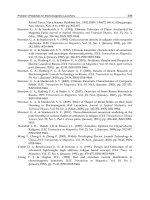
Fig. 15. Temperature distributions of the combustor wall
Figure 15 shows temperature distributions of the combustor wall. For the cases A2 and B,
hot regions exist around the middle axial positions. In case C, the hot region is located
Heat Transfer - Mathematical Modelling, Numerical Methods and Information Technology
470
further downward axial position compared with cases A2 and B. These phenomena are
matched well with the wall Nusselt number distributions. This may decrease the
combustion efficiency because of big heat loss from the combustor inside. However, if hot
gases are recirculated as in the case of the MGT proposed by (Suzuki et al., 2000), the effect
of this heat loss may be mitigated.
Fig. 16. Contour of Θ/Θmax and velocity vector fields at (x, z) cross-sectional plane. (a) Case
A1; (b) case A2; and (c) case A3
To look into the effect of velocity or momentum ratio between fuel jet and oxidant jet flows
for the recommended case A2, the cases A1, A2 and A3 are calculated as in Table 1 with the
same geometry and similar Reynolds number. Figure 16 shows the contours of time
averaged temperature both in the flow field and conjugate wall together with velocity vector
fields. With increasing velocity ratio the central recirculation region is generated and the
width(streamwise direction) and height(wall-normal direction) of the recirculation region
are changed. This greatly affects the evolution of flow and thermal fields. In Figure 16, the
near-wall recirculation region exists for the three cases and another tiny recirculation bubble
is shown at upstream very close to the baffle plate. In case A1, the path of oxidant jet flow is
going toward the wall following streamline of the near-wall recirculation region and at that
region close to the wall temperature gradient becomes steep and the temperature gradient of
the conjugated wall, too. For cases A2 and A3, the central recirculation region is generated
but its configuration is different. In case A2, the central recirculation region looks circular in
shape and above it the streamline is curved following it. So, the recirculation region pushes
more the oxidant jet flow to upward compared with case A1 and this results in the thinnest
thermal boundary layer among the three cases. In case A3 the central recirculation region
resembles ellipsoidal shape. Furthermore, according to increased oxidant jet momentum the
starting point of the recirculation region appears earlier compared with the case A2. This
makes the streamline of the oxidant jet flow partly downward earlier toward the center of
Turbulent Flow and Heat Transfer Characteristics of a Micro Combustor
471
the combustor tube. Therefore, the temperature gradient around / 6
f
xD
=
is the mildest
among the three cases.
Fig. 17. Instantaneous contour of Q1 and velocity vector fields at (x, z) cross-sectional plane.
(a) Case A1; (b) case A2; and (c) case A3
In Figure 17, for all the three cases the instantaneous near-wall recirculation region is
generated, but the central flow recirculation region can be shown only in (b) and (c). In case
A1, following the outer streamline of the near-wall recirculation region, the oxidant jet is
bent toward the wall and the parcels of fuel jet fluids are entrained into the oxidant jet flow
because of higher momentum of the oxidant jet. The
1
Q is higher at the regions between
fuel and oxidant jets and around the upward flow of the near-wall recirculation region.
With increasing velocity ratio in cases (b) and (c), the central recirculation region appears
due to smaller fuel jet momentum and this deforms the direction of the oxidant jet flow. In
case A2, the velocity of upward flow near the reattachment region is larger than that of case
A1 because the passage of oxidant jet becomes narrower by the central flow recirculation
region. The larger wall-ward velocity makes
1
Q higher at that region and the level of
1
Q is
elevated than that of the region between fuel jet and oxidant jet flows. This makes the
thermal boundary layer thinner resulting in steep temperature gradient close to the wall.
However, in case A3, the location of the central recirculation region is pulled more upstream
because of increased oxidant jet momentum compared with fuel jet one and the shape of the
the central recirculation region becomes flatter as ellipsoid. Especially, at this instant of the
Heat Transfer - Mathematical Modelling, Numerical Methods and Information Technology
472
case, the direction of oxidant jet is changed toward the center region of the combustor tube.
Therefore around the near-wall recirculation region the strength of wall-ward fluid motion
is decreased. This results in the reduction of
1
Q
at that region. These instantaneous thermal
features are repeated and finally have an effect on time-averaged values as discussed before.
From the above results, in case of the same baffle plate configuration, the variation of
velocity ratio makes the heat loss different in quantity and from this point of view the case
A3 might be recommended for a micro combustor.
Fig. 18. Comparison of heat loss
Finally, Figure 18 shows the heat loss percentage of the combustor and volume averaged
temperature of the fluid for all the cases. Here, the heat loss is defined as the total heat flux
passing through the annular wall of the combustor. These are averaged over the combustor
wall surface and normalized by heat input. As expected the previous figures, with varying
baffle plate shape the total heat loss is increased in the order from the case A2 to B and
finally case C. Also, with changing the velocity ratio case A3 has the lowest heat loss. So, the
case A3 has the best thermal performance against the heat loss. From the results, for a
method to reduce heat loss in the micro combustor, it is recommended that when the near-
wall recirculation region exists, its momentum of negative streamwise direction should be
decreased. It is noted that the heat generation by combustion should be considered for total
thermal energy budget, which is closely connected with mixing efficiency and will be
discussed in the future study and from the work of (Choi et al., 2005; Choi et al., 2006a; Choi
et al., 2008), the flow recirculation regions can greatly help the mixing enhancement between
fuel and oxidant. So, there should be the compromise between mixing enhancement and
reduction of heat loss for stable and complete combustion.
4. Conclusion
In this chapter, heat transfer characteristics of multiple jet flows in a micro combustor is
investigated by using Large Eddy Simulation (LES). The micro combustor is characterized
Turbulent Flow and Heat Transfer Characteristics of a Micro Combustor
473
by a baffle plate having single fuel nozzle surrounded by six oxidant nozzles annularly and
study was made in the three cases of different baffle plate configurations. The baffle plate is
mounted to enhance the slow scalar mixing in the low Reynolds number condition of the
micro combustor and to hold the flame stable.
With varying baffle plate shapes as the cases of A2, B, and C, the central and near-wall
recirculation region appear differently according to the velocity ratio, which is controlled by
the configuration and size of the nozzle. In cases with the baffle plates A2 and C, central
flow recirculation region is generated and turbulent mixing proceeds more effectively than
in the case with the baffle plate B where no central flow recirculation region appears. As a
result, mixing is found to be greatly affected by the near-wall flow recirculation regions
formed between jets and wall and the central flow recirculation region formed downstream
the fuel jet flow. In case C, air jet velocity is high and ring vortices appear most noticeably,
intermingling with each other and develop most effectively into turbulent vortices. Also,
high momentum of air jet flow brings about the upstream movement of the central flow
recirculation region and results in the completion of turbulent mixing within a shorter
distance from the baffle plate.
The near-wall recirculation region plays an important role for wall heat transfer, especially
near the reattachment region. The central recirculation region only appears in the cases A2
and C and helps turbulent heat transfer to the wall near the reattachment region affecting
wall-ward flow. The reattachment flow pushes the hot fluid lumps into the combustor tube
wall and this leads to the thinner thermal boundary layer representing higher wall heat
transfer there. Among the three cases of different baffle geometry, the case A2 has the
smallest wall heat loss, so the case A2 may be recommended for better design of the micro
combustor. For this case, to investigate the velocity ratio effect on the same recommended
geometry, numerical study is made for the three cases of A1, A2 and A3. With changing the
velocity ratio for the cases A1, A2 and A3, the existence and the shape of the central and the
near-wall recirculation regions are varied resulting in different heat loss characteristics.
Among the three cases, the case A3 shows the minimum heat loss in the present study. It is
noted that to prevent the big heat loss, the method of hot gas recirculation by (Suzuki et al.,
2000) may be one solution so that the effect of the heat loss may be mitigated.
5. References
Andreopoulos, J. (1993). Heat Transfer Measurement in a Heated Jet-Pipe Flow Issuing into
a Cold Cross Stream, Phys. Fluids, Vol. 26, pp. 3201-3210, ISSN:1070-6631.
Benard, P. S. & Wallace, J. M. (2002). Turbulent Flow, John Willey & Sons Inc., Hoboken, NJ.
Choi, H. S., Nakabe, K., Suzuki K. & Katsumoto, Y. (2001). An Experimental Investigation of
Mixing and Combustion Characteristics on the Can-Type Micro Combustor with a
Multi-Jet Baffle Plate, Fluid Mechanics and Its Application, Vol. 70, pp. 367-375,
ISSN:0926-5112.
Choi, H. S., Park, T. S. & Suzuki, K. (2005). LES of Turbulent Flow and Mixing in a Micro
Can Combustor, Proc. 4th Int. Symposium Turbulence and Shear Flow Phenomena, Vol.
2, pp. 389-394.
Choi, H. S., Park, T. S. & Suzuki, K. (2006a). Numerical Analysis on the Mixing of a Passive
Scalar in the Turbulent Flow of a Small Combustor by Using Large Eddy
Simulation, Journal of Computational Fluid Engineering (Korean), Vol. 11, pp. 67-74,
ISSN:1598-6071.
Heat Transfer - Mathematical Modelling, Numerical Methods and Information Technology
474
Choi, H. S., Park, T. S. & Suzuki, K. (2008). Turbulent Mixing of a Passive Scalar in Confined
Multiple Jet Flows of a Micro Combustor, Int. J. Heat Mass Transfer, Vol. 51, pp.
4276-4286, ISSN:0017-9310.
Choi, H. S., Park, T. S. & Suzuki, K. (2006b). Large Eddy Simulation of Turbulent Convective
Heat Transfer in a Micro Can Combustor with Multiple Jets, Proc. 13th Int. Heat
Transfer Conference, Vol. 1, pp. TRB-22.
Choi, H. S. & Park, T. S. (2009). A Numerical Study for Heat Transfer Characteristics of a
Micro Combustor by Large Eddy Simulation, Numerical Heat Trnasfer Part A, Vol.
56, pp. 230-245, ISSN:1040-7782
Ferziger, J. H. & Peric, M. (2002). Computational Methods for Fluid Dynamics, 3rd ed., Springer-
Verlag, Berlin, ISBN:3-540-42074-6.
Issa, R. I. (1986). Solution of the Implicitly Discretized Fluid Flow Equations by Operating-
Splitting, J. Comput. Phys., Vol. 62, pp. 40-65, ISSN:0021-9991.
Kee, R. J., Zhu, H. & Goodwin, D. G. (2005). Solid-Oxide Fuel Cells with Hydrocarbon
Fuels, Proceedings of the Combustion Institute, Vol. 30, pp. 2379-2404, ISSN:1540-7489.
Le, H., Moin, P. And Kim, J. (1997). Direct Numerical Simulation of Turbulent Flow over a
Backward-Facing Step, J. Fluid Mechacnics, Vol. 330, pp. 349-374.
Lele, S. K. (1992). Compact Finite Difference Schemes with Spectral-Like Resolution, J.
Comput. Phys., Vol. 103, pp. 16-42, ISSN:0021-9991.
Lilly, D. K. (1992). A Proposed Modification of the Germano Subgrid-Scale Closure Model,
Phys. Fluids, Vol. 4, pp. 633-635, ISSN:1070-6631.
Massardo, A. F. & Lubelli, F. (2000). Internal Reforming Solid Oxide Fuel Cell-Gas Turbine
Combined Cycles(IRSOFCGT) :Part A-Cell Model and Cycle Thermodynamics
Analysis, ASME Journal of Engineering for Gas Turbine and Power, Vol. 122, pp. 27-35,
ISSN:0742-4795.
Mcdonald, C. F. (2000). Low Cost Compact Primary Surface Recuperator Concept for
Microturbine, Applied thermal Engineering, Vol. 20, pp. 471-497, ISSN:1359-4311.
Moin, P., Squires, K., Cabot, W. & Lee, S. (1991). A Dynamic Subgrid-Scale Model for
Compressible Turbulence and Scalar Transport, Phys. Fluids, Vol. 3, pp. 2746-2757,
ISSN:1070-6631.
Park, T. S. (2006a). Effect of Time-Integration Method in a Large Eddy Simuation using PISO
Algorithm: Part I-Flow Field, Numerical Heat Trnasfer Part A, Vol. 50, pp. 229-245,
ISSN:1040-7782.
Park, T. S. (2006b). Effect of Time-Integration Method in a Large Eddy Simuation using PISO
Algorithm: Part II-Thermal Field, Numerical Heat Trnasfer Part A, Vol. 50, pp. 247-
262, ISSN:1040-7782.
Park, T. S., Sung, H. J. & Suzuki, K. (2003). Development of a Nonlinear Near-Wall
Turbulence Model for Turbulent Flow and Heat Transfer, Int. J. Heat Fluid Flow,
Vol. 24, pp. 29-40, ISSN:0142-727X.
Peng, S. H. & Davision, L. (2002). On a Subgrid-Scale Heat Flux Model for Large Eddy
Simulation of Turbulent Flow, Stream, Int. J. Heat Mass Transfer, Vol. 45, pp. 1393-
1405, ISSN:0017-9310.
Suzuki, K., Teshima, K. & Kim, J. H. (2000). Solid Oxide Fuel Cell and Micro Gas Turbine
Hybrid Cycle for a Distributed Energy Generation System, Proc. 4th JSME-KSME
Thermal Engineering Conference, Vol. 13, pp. 1-8.
19
Natural Circulation in Single and
Two Phase Thermosyphon Loop with
Conventional Tubes and Minichannels
Henryk Bieliński and Jarosław Mikielewicz
The Szewalski Institute of Fluid-Flow Machinery, Polish Academy of Sciences,
Fiszera 14, 80-952 Gdańsk,
Poland
1. Introduction
The primary function of a natural circulation loop (i.e. thermosyphon loop) is to transport
heat from a source to a sink. Fluid flow in a thermosyphon loop is created by the buoyancy
forces that evolve from the density gradients induced by temperature differences in the
heating and cooling sections of the loop. An advanced thermosyphon loop consists of the
evaporator, where the working liquid boils; and the condenser, where the vapour condenses
back to liquid; the riser and the downcomer connect these two exchangers. Heat is
transferred as the vaporization heat from the evaporator to the condenser. The
thermosyphon is a passive heat transfer device, which makes use of gravity for returning
the liquid to the evaporator. Thermosyphons are less expensive than other cooling devices
because they feature no pump.
There are numerous engineering applications for thermosyphon loops such as, for example,
solar water heaters, thermosyphon reboilers, geothermal systems, nuclear power plants,
emergency cooling systems in nuclear reactor cores, electrical machine rotor cooling, gas
turbine blade cooling, thermal diodes and electronic device cooling. The thermal diode is
based on natural circulation of the fluid around the closed-loop thermosyphon (Bieliński &
Mikielewicz, 1995, 2001), (Chen, 1998). The closed-loop thermosyphon is also known as a
“liquid fin” (Madejski & Mikielewicz, 1971).
Many researchers focused their attention on the single-phase loop thermosyphons with
conventional tubes, and the toroidal and the rectangular geometry of the loop. For example,
Zvirin (Zvirin, 1981) presented results of theoretical and experimental studies concerned with
natural circulation loops, and modeling methods describing steady state flows, transient and
stability characteristics. Greif (Greif, 1988) reviewed basic experimental and theoretical work
on natural circulation loops. Misale (Misale et al., 2007) reports an experimental investigations
related to rectangular single-phase natural circulation mini-loop. Ramos (Ramos et al., 1985)
performed the theoretical study of the steady state flow in the two-phase thermosyphon loop
with conventional tube. Vijayan (Vijayan et al., 2005) compared the dynamic behaviour of the
single-phase and two-phase thermosyphon loop with conventional tube and the different
displacement of heater and cooler. The researcher found that the most stable configuration of
the thermosyphon loop with conventional tube is the one with both vertical cooler and heater.
Heat Transfer - Mathematical Modelling, Numerical Methods and Information Technology
476
In the case of closed rectangular and toroidal loops with conventional tube, particular
attention has to be devoted to both transient and steady state flows as well as to stability
analysis of the system under various heating and cooling conditions.
The purpose of this chapter is to present a detailed analysis of heat transfer and fluid flow in
a new generalized model of thermosyphon loop and its different variants. Each individual
variant can be analyzed in terms of single- and two-phase flow in the thermosyphon loop
with conventional tubes and minichannels. The new empirical correlations for the heat
transfer coefficient in flow boiling and condensation, and two-phase friction factor in
diabatic and adiabatic sectors in minichannels and conventional tube, are used to simulate
the two-phase flow and heat transfer in the thermosyphon loop. The analysis of the
thermosyphon loop is based on the one-dimensional model, which includes mass,
momentum and energy balances.
2. A generalized model of the thermosyphon loop
A schematic diagram of a one-dimensional generalized model of the thermosyphon loop is
shown in Fig. 1.
7
9
C3
H1
C2
L
L
L
L
L
C3
H1
H2
C1
C1K
11
10
4
5
12
6
8
L
L
L
L
13
15
1
14
0
16
2
3
H2
H3
C1
S
S
S
S
S
S
S
S
S
S
S
S
S
S
S
S
S
H3P
H2P
H2
C1
C3P
C2P
H1K
L
L
L
Fig. 1. A schematic diagram of a one-dimensional generalized model of the thermosyphon
loop.
The loop has a provision for selecting one or two or three of the heat sources at any location,
in the bottom horizontal pipe or in the vertical leg; similarly, the heat sink can be chosen in
the top horizontal pipe or in the vertical leg. Therefore, any combination of heaters and
coolers can be analyzed. The constant heat fluxes
H
q
and
C
q
are applied in the cross-
Natural Circulation in Single and Two Phase Thermosyphon Loop
with Conventional Tubes and Minichannels
477
section area per heated and cooled length:
H
L
and
C
L
. The heated and cooled parts of the
thermosyphon loop are connected by perfectly insulated channels. The coordinate s along
the loop and the characteristic geometrical points on the loop are marked with s
j
, as shown
in Fig. 1. The total length of the loop is denoted by L, the cross-section area of the channel by
A and the wetted perimeter by
U
. Thermal properties of fluid:
ρ
- density,
p
c
- heat
capacity of constant pressure,
λ
- thermal conductivity.
The following assumptions are used in the theoretical model of natural circulation in the
closed loop thermosyphon:
1. thermal equilibrium exists at any point of the loop,
2. incompressibility because the flow velocity in the natural circulation loop is relatively
low compared with the acoustic speed of the fluid under current model conditions,
3. viscous dissipation in fluid is neglected in the energy equations,
4. heat losses in the thermosyphon loop are negligible,
5.
()
;1LD << one-dimensional models are used and the flow is fully mixed. The velocity
and temperature variation at any cross section is therefore neglected,
6. heat exchangers in the thermosyphon loop can be equipped by conventional tubes or
minichannels,
7. fluid properties are constants, except density in the gravity term,
8. single- and two-phase fluid can be selected as the working fluid,
a. if the Boussinsq approximation is valid for a single-phase system, then density is
assumed to vary as
(
)
[
]
00
TT1
−
⋅
β
−
⋅
ρ
=
ρ
in the gravity term where
p
0
T
1
⎟
⎠
⎞
⎜
⎝
⎛
∂
υ∂
⋅
υ
=β
( υ - specific volume, “0” is the reference of steady state),
b. for the calculation of the frictional pressure loss in the heated, cooled and adiabatic
two-phase sections, the two-phase friction factor multiplier
2
0L
R φ= is used; the
density in the gravity term can be approximated as follows:
()
LV
1 ρ⋅α−+
ρ
⋅
α
=
ρ
,
where α is a void fraction,
c.
homogeneous model or separate model can be used to evaluate the friction
pressure drop of two phase flow,
d.
quality of vapor in the two-phase regions is assumed to be a linear function of the
coordinate around the loop,
9.
the effect of superheating and subcooling are neglected,
Under the above assumptions, the governing equations for natural circulation systems can
be written as follows:
-
conservation of mass:
()
;0w
s
=⋅ρ
∂
∂
+
∂τ
∂ρ
(1)
where
τ
- time,
w
- velocity.
-
conservation of momentum:
;
A
U
g
~
s
p
s
w
w
w
w
⋅τ−⋅ρ⋅ε+
∂
∂
−=
⎟
⎠
⎞
⎜
⎝
⎛
∂
∂
⋅+
∂τ
∂
⋅ρ
(2)
where
(
)
(
)
;gefor1;gefor1;gefor0 ↓∧↓−=ε↓∧↑+=ε⊥=ε
G
G
G
G
G
G
;)g,ecos(g1geg
~
GG
G
D
G
⋅⋅==
;1e;gg ==
G
G
and e
G
is a versor of the coordinate around the loop, and
w
τ
- wall shear stress.
Heat Transfer - Mathematical Modelling, Numerical Methods and Information Technology
478
In order to eliminate the pressure gradient and the acceleration term, the momentum
equation in Eq. (2) is integrated around the loop
∫
=
⎟
⎠
⎞
⎜
⎝
⎛
∂
∂
0ds
s
p
.
-
conservation of energy:
⎪
⎪
⎪
⎪
⎩
⎪
⎪
⎪
⎪
⎨
⎧
⋅ρ⋅
⋅
+
⋅ρ⋅
⋅
−
+
∂
∂
⋅=
∂
∂
⋅+
∂τ
∂
tionsecheated
for
Ac
Uq
tionseccooled for
Ac
Uq
tionsecadiabaticfor0
s
T
a
s
T
w
T
0p
H
0p
C
2
2
0
0
0
(3)
where
0
p0
0
0
c
a
⋅ρ
λ
=
- thermal diffusivity,
The flow in natural circulation systems which is driven by density distribution is also
known as a gravity driven flow or thermosyphonic flow. In such flows, the momentum and
the energy equations are coupled and for this reason they need to be simultaneously solved
(Mikielewicz, 1995).
3. Thermosyphon loop Heated from below Horizontal side and Cooled from
upper Horizontal side (HHCH).
In this paper, we present the case of the onset of motion of the single-phase fluid from a rest
state, which occurs only for the (HHCH) variant. We have assumed that:
(
)
0CC
TTq −⋅α
=
.
The heat transfer coefficient between the wall and environment
C
α
and the temperature of
the environment
0
T are constant.
S
0
S
S
1
S
2
S
3
4
B
H
s
q
H
INSULATION
;
T
0C
a
Fig. 2. The variant of HHCH.
Natural Circulation in Single and Two Phase Thermosyphon Loop
with Conventional Tubes and Minichannels
479
The above governing equations can be transformed to their dimensionless forms by the
following scaling:
;
)Lq(
)TT()U/A(
T;)Aa()Lm(m;L/ss;L/)a(
2
H
0H0
00
2
0
⋅
−⋅⋅λ
=⋅ρ⋅⋅==τ⋅=τ
++++
(4)
The dimensionless momentum equation and the energy equation at the steady state for the
thermosyphon loop heated from below can be written as follows:
-
momentum equation (with: ;LsK
jj
=
)
;dsTdsT)Ra(m
3
2
1
K
K
K
0
**
⎟
⎟
⎟
⎠
⎞
⎜
⎜
⎜
⎝
⎛
−⋅=
∫∫
+++++
(5)
-
energy equation
tionsecheater
tionseccooling
tionssecinsulated
for
1
T)Bi(
0
ds
Td
ds
dT
m
**
2
2
⎪
⎪
⎪
⎩
⎪
⎪
⎪
⎨
⎧
+
⋅−
+
=
+
+
+
+
+
+
(6)
-
with boundary conditions
;
ds
dT
ds
dT
;
ds
dT
ds
dT
;
ds
dT
ds
dT
;
ds
dT
ds
dT
;)K(T)K(T;)K(T)K(T;)K(T)K(T;)1(T)0(T
332
2
1
1
Ks
H
Ks
2A
Ks
2A
Ks
C
Ks
C
Ks
1A
1s
H
0s
1A
3H32A22A2C1C11AH1A
=
+
+
=
+
+
=
+
+
=
+
+
=
+
+
=
+
+
=
+
+
=
+
+
++++++++
+++
+
+
+++
==
==
====
(7)
The parameters appearing in the momentum and the energy equations are the modified
Biot, Rayleigh and Prandtl numbers.
;
aA
U
L2(Pr);
U2
UA
a
)/q(Lg
)Ra(;
A
L
U
)Bi(
0
0
2
2**
2
H
00
0H
3
0
**
2
0
CC
**
⎟
⎟
⎠
⎞
⎜
⎜
⎝
⎛
ν
⋅
⎟
⎟
⎠
⎞
⎜
⎜
⎝
⎛
⋅⋅=
⋅
⋅
⋅
⋅ν
λ⋅⋅β⋅
=⋅
λ
⋅α
=
(8)
For the discussed case of laminar steady-state flow the dimensionless distributions of
temperature around the loop can be obtained analytically from Eq. (6). Working fluid was
the distilled water. The results of calculations are presented in Fig. 3.
It has been found that the Biot number has an influence on temperature and mass flow rate
in the laminar flow. The results are shown in Figs. 3 and 4.
Substitution of the temperature distributions into the dimensionless equation of motion for
the steady-state yields the relation for the dimensionless flow rate for laminar flow.
The presented numerical calculations are based on our new method for solution of the
problem for the onset of motion in the fluid from the rest. Conditions for the onset of motion
Heat Transfer - Mathematical Modelling, Numerical Methods and Information Technology
480
0,0 0,2 0,4 0,6 0,8 1,0
0,0
4,0x10
-5
8,0x10
-5
1,2x10
-4
T
+
A1
T
+
A2
T
+
C
T
+
H
(Bi)
**
= 5*10
5
(Bi)
**
=1*10
4
DIMENSIONLESS TEMPERATURE T
+
DIMENSIONLESS COORDINATE s
+
Fig. 3. The effect of Biot number on temperatures in laminar steady-state flow (HHCH).
1x10
3
1x10
3
2x10
3
2x10
3
3x10
3
3x10
3
4x10
3
4x10
3
00
5
1010
15
(Bi)
**
= 1*10
-1
(Bi)
**
= 1*10
2
(Bi)
**
= 1*10
3
(Bi)
**
= 1*10
4
(Bi)
**
= 5*10
4
MASS FLOW RATE m
+
MODIFIED RAYLEIGH NUMBER (Ra)
**
Fig. 4. The dimensionless mass flow rate
+
m
versus modified Rayleigh number
()
**
Ra with
the modified Biot number
(
)
**
Bi used as a fixed parameter (HHCH) .
in the thermosyphon can be determined by considering the steady solutions with circulation
for the limiting case of
0m
l
→
+
. The analysis was based on the equations of motion and
energy for the steady-state conditions. The heat conduction term has to be taken into
account in this approach because the heat transfer due to conduction is becoming an
increasingly important factor for decreasing mass flow rates.
Natural Circulation in Single and Two Phase Thermosyphon Loop
with Conventional Tubes and Minichannels
481
It is shown that the geometrical and thermal parameters have an influence on the problem
of global flow initiation from the rest (Figs. 4, 5 and 6).
Fig. 5 illustrates that the larger Biot numbers correspond to larger values of the critical
Rayleigh number.
1x10
-2
1x10
3
1x10
8
600
800
1000
1200
1400
CRITICAL VALUE
RAYLEIGH NUMBER (Ra)
**
MODIFIED BIOT NUMBER (Bi)
**
Fig. 5. The critical value of the modified Rayleigh number
(
)
**
Ra versus modified Biot
number
**
)Bi( (HHCH).
10
-3
10
-1
10
1
10
3
1x10
2
1x10
4
1x10
6
CRITICAL VALUE MODIFIED
RAYLEIGH NUMBER (Ra)
**
B / H
Fig. 6. The critical value of the modified Rayleigh number
(
)
**
Ra versus B/H ratio (HHCH).
It has been found that the minimum of the critical modified Rayleigh number
()
**
Ra =1121,
with
5**
102)Bi( ×= , appears for B/H=0.544.
The stability analysis shows that the loop heated from one side and cooled from the other
one asymmetrically with respect to the gravity force is always unstable and any temperature
gradient due to heating or cooling results in the onset of flow circulation.
Heat Transfer - Mathematical Modelling, Numerical Methods and Information Technology
482
4. Thermosyphon loop Heated from the lower part of Vertical side and Cooled
from the upper part of the opposite Vertical side (HVCV).
The thermosyphon loop heated from the lower part of vertical leg and cooled from the
upper part of the opposite vertical leg (HVCV) is chosen as an example to present the
analysis of two-phase flow in conventional tubes. The Stomma (Stomma, 1979) correlation
describing the void fraction, the Friedel (Friedel, 1979) correlation for the friction pressure
drop of two-phase flow in adiabatic region, the Müller-Steinhagen & Heck (Müller-
Steinhagen & Heck, 1986) correlation for the friction pressure drop of two-phase flow in
diabatic region and the Mikielewicz correlation for the flow boiling heat transfer coefficient
in conventional channels (Mikielewicz et al., 2007) are used to calculate two phase flow in
the thermosyphon loop equipped with conventional tubes. Freon R-11 was chosen as a
working fluid in the thermosyphon device.
A schematic diagram of the analysed
thermosyphon loop (HVCV) is shown in Fig. 7.
C
L
L
C
H
L
H
0H
0C
L
S
S
S
S
S
S
S
S
S
0
8
1
2
3
4
5
6
7
Fig. 7. The thermosyphon loop heated from the lower part of vertical side and cooled from
the upper part of the opposite vertical side (HVCV).
After integrating the gravitational term in the momentum equation (2) around the loop, we
obtain
()
{
}
()
()
() () ()
{}
14
01 45
21 43 10 54
;
;;
1
;
LV
VL
ss
ss ss
gds
gssssssss
εαραρ
ρρ α α α
⋅⋅⎡ − ⋅ +⋅ ⎤ =
∫
⎣⎦
⎡⎤
=⋅ − × − − − ⋅ + − ⋅ − − ⋅
⎣⎦
v
(9)
where
()
()
dss
ss
1
K
P
KPKP
s
s
s;s
PK
s;s
∫
α⋅
−
=α .
Natural Circulation in Single and Two Phase Thermosyphon Loop
with Conventional Tubes and Minichannels
483
The Stomma empirical correlation (Stomma, 1979) for the void fraction at low pressures is
applied in the form
()
()
()
2
2
1
1
2ln
1
HOM
STOMMA
HOM
HOM
x
x
x
α
α
α
α
⎡⎤
−
⎢⎥
⎣⎦
=−
⎡
⎤
⎛⎞
−
⋅−−
⎢
⎥
⎜⎟
−
⎢
⎥
⎝⎠
⎣
⎦
(10)
where
⎟
⎟
⎠
⎞
⎜
⎜
⎝
⎛
ρ
ρ
⋅
−
+
=α
L
V
HOM
x
x1
1
1
. (Subscripts: V – vapour, L – liquid, HOM - homogeneous).
The following additional assumptions are made in this study (HVCV): a) flows of liquid and
vapour phases in the two-phase regions are both turbulent and flow of liquid in single
phase region is also turbulent, b) friction coefficient is constant in each region of the loop
and the frictional component of the pressure gradient in two-phase regions was calculated
according to the two-phase separate model. Due to the friction of fluid, the pressure losses
in two-phase regions can be calculated as
0Lp2
w
ds
dp
R
ds
dp
A
U
⎟
⎠
⎞
⎜
⎝
⎛
−
⋅=
⎟
⎠
⎞
⎜
⎝
⎛
−
=τ⋅ (11)
where:
(
)
L
2
Chur
0L
0L
D
Gf2
ds
dp
ρ⋅
⋅⋅
=
⎟
⎠
⎞
⎜
⎝
⎛
is the liquid only frictional pressure gradient calculated for
the total liquid mass velocity, wG ⋅ρ=
,
Chur
0L
f is friction factor of the fluid (Churchill, 1977).
The local two-phase friction coefficient in two-phase adiabatic region was calculated using
the Friedel formula (Friedel, 1979):
;
ds
dp
ds
dp
0L
2
0L
FRIEDEL
Frict,f2
⎟
⎠
⎞
⎜
⎝
⎛
⋅Φ=
⎟
⎠
⎞
⎜
⎝
⎛
(12)
where
() ( )
;
WeFr
HF24.3
E
035.0045.0
2
0L
⋅
⋅⋅
+=Φ
and
() () ( )
;1H;x1xF;
f
f
xx1E
7.0
L
V
19.0
L
V
91.0
V
L
224.078.0
0LV
0VL
2
2
⎟
⎟
⎠
⎞
⎜
⎜
⎝
⎛
μ
μ
−
⎟
⎟
⎠
⎞
⎜
⎜
⎝
⎛
μ
μ
⋅
⎟
⎟
⎠
⎞
⎜
⎜
⎝
⎛
ρ
ρ
=−⋅=
⋅ρ
⋅ρ
⋅+−=
and ( σ - surface tension)
()
(
)
()
()
(
)
()
;
DG
We;
Dg
G
Fr
HOM
2
2
HOM
2
σ⋅ρ
⋅
=
ρ⋅⋅
=
The local two-phase friction coefficient in two-phase diabatic regions was calculated using
the Müller-Steinhagen & Heck formula (Müller-Steinhagen & Heck, 1986)
Heat Transfer - Mathematical Modelling, Numerical Methods and Information Technology
484
()
;xBx1F
ds
dp
3
3
1
SM
Frict,f2
⋅+−⋅=
⎟
⎠
⎞
⎜
⎝
⎛
−
(13)
where
()
;
ds
dp
B;
ds
dp
A;ABx2AF
0V0L
⎟
⎠
⎞
⎜
⎝
⎛
=
⎟
⎠
⎞
⎜
⎝
⎛
=−⋅⋅+=
After integrating the friction term in Eq. (2) around the loop, we obtain
()
()
() ()
{
}
;ssRssRssRss
ds
dp
ds
A
U
58
s;s
45
s;s
14
s;s
01
0L
w
54
41
10
−+⋅−+⋅−+⋅−⋅
⎟
⎠
⎞
⎜
⎝
⎛
=
⎟
⎠
⎞
⎜
⎝
⎛
τ⋅
∫
(14)
where:
()
()
dssR
ss
1
R
K
P
KP
s
s
PK
s;s
∫
⋅
−
= .
Thus the momentum equation (2) for the two-phase thermosyphon loop (HVCV) can be
written as
()
()
() ()
{}
()
()
()
[]
() ()
{}
;0ssssssssg
ssRssRssRss
ds
dp
5410
41
54
41
10
s;s
45
s;s
01
s;s
3412LV
58
s;s
45
s;s
14
s;s
01
0L
=α⋅−−α⋅−+α⋅−−−⋅ρ−ρ⋅+
+−+⋅−+⋅−+⋅−⋅
⎟
⎠
⎞
⎜
⎝
⎛
(15)
The mass flux distributions
G
versus heat flux
H
q
for the steady-state conditions and for
the conventional tube case, is shown in Fig. 8. Calculations were carried out also using the
homogeneous model of two-phase flow. The working fluid was freon R11.
1x10
4
2x10
4
3x10
4
4x10
4
4,0x10
2
8,0x10
2
1,2x10
3
FDR
G [ kg / m
2
*s ]
q
H
[ W / m
2
]
SEPARATED
HOMOGENEOUS
GDR
Fig. 8. Mass flux rate
G
as a function of
H
q
for homogeneous model and separate model of
two-phase flow (HVCV), (L=2 [m], D=0.08 [m], H=0.9 [m], B=0.1 [m], L
H
=L
C
=0.2 [m],
L
HP
=L
CP
=0.05 [m] ).
Natural Circulation in Single and Two Phase Thermosyphon Loop
with Conventional Tubes and Minichannels
485
Two flow regimes can be clearly identified in Fig. 8, namely GDR - gravity dominant regime
and FDR – friction dominant regime. In the gravity dominant regime, for a small change in
quality there is a large change in the void fraction and therefore density and buoyancy force.
The increased buoyancy force can be balanced by a significant increase in the corresponding
frictional force which is possible only at higher flow rates. As a result, the gravity dominant
regime is characterized by an increase in the flow rate with heat flux
H
q
. However, the
continued conversion of high density water to low density steam due to increase in heat flux
H
q
requires that the mixture velocity must increase resulting in the increase of the frictional
force and hence a decrease in flow rate. Thus the friction dominant regime is characterized
by a decrease in flow rate with increase in heat flux
H
q
(Vijayan et al., 2005). As presented
in Fig. 8 a comparison between two models of two-phase flow shows that the homogeneous
and the separated flow models reveal relatively big differences.
4.1 The distributions of heat transfer coefficient in flow boiling.
The heat transfer coefficient in flow boiling in minichannels was calculated using the
Mikielewicz general formula for conventional channels (Mikielewicz et al., 2007)
()
;
h
h
P1
1
R
h
h
2
REF
PB
n
SM
REF
JM
TPB
⎟
⎟
⎠
⎞
⎜
⎜
⎝
⎛
⋅
+
+=
−
(16)
where
()
;
f
1
xx1x1
f
1
21R
z1
3
3
1
1
SM
⋅+−⋅
⎥
⎥
⎦
⎤
⎢
⎢
⎣
⎡
⋅
⎟
⎟
⎠
⎞
⎜
⎜
⎝
⎛
−⋅+=
−
()
()
;
c
c
f;f
;PrRe
D
023.0h;76.0nTUR
2
3
V
L
3
1
pV
pL
15
7
L
V
TUR
z1
L
V
25.0
V
L
TUR
1
3
1
L
8.0
0L
L
REF
⎟
⎟
⎠
⎞
⎜
⎜
⎝
⎛
λ
λ
⋅
⎟
⎟
⎠
⎞
⎜
⎜
⎝
⎛
⋅
⎟
⎟
⎠
⎞
⎜
⎜
⎝
⎛
μ
μ
=
⎟
⎟
⎠
⎞
⎜
⎜
⎝
⎛
ρ
ρ
⋅
⎟
⎟
⎠
⎞
⎜
⎜
⎝
⎛
μ
μ
=
⋅⋅
λ
⋅==⇒
(
)
(
)
(
)
(
)
(
)
;1RBoRe1053.2P
65.0
SM
6.017.1
0L
3
−
−
−
−⋅⋅⋅×=
()
(
)
()
()
;
dG
Re;
rG
q
Bo;
P
P
log
P
P
Mq55h
L
0L
55.0
CRIT
n
10
12.0
CRIT
n
5.067.0
PB
μ
⋅
=
⋅
=
⎥
⎥
⎦
⎤
⎢
⎢
⎣
⎡
⎟
⎟
⎠
⎞
⎜
⎜
⎝
⎛
−⋅
⎟
⎟
⎠
⎞
⎜
⎜
⎝
⎛
⋅⋅⋅=
−
−
For comparison purposes the heat transfer coefficient for flow boiling in minichannels was
also calculated using the Liu and Winterton formula (Liu & Winterton, 1991):
(
)
()
;hShFh
2
PB
2
REF
WL
TPB
⋅+⋅=
−
(17)
where
()
()
()
()
;
Dg
G
)Fr(;
ReF055.01
1
S;1Prx1F
2
L
16.1
0L
1.0
35.0
V
L
L
⋅⋅ρ
=
⎥
⎥
⎦
⎤
⎢
⎢
⎣
⎡
⋅⋅+
=
⎥
⎥
⎦
⎤
⎢
⎢
⎣
⎡
⎟
⎟
⎠
⎞
⎜
⎜
⎝
⎛
−
ρ
ρ
⋅⋅+=
Heat Transfer - Mathematical Modelling, Numerical Methods and Information Technology
486
The heat transfer coefficient distributions in flow boiling for minichannels
TPB
h
versus heat
flux
H
q
for the steady-state conditions are presented in Fig. 9.
2x10
4
4x10
4
3x10
3
6x10
3
HVCV
CONVENTIONAL TUBE
HEATER_CORRELATION: h
TPB
= f(q
H
)
MIKIELEWICZ (2007)
LIU-WINTERTON (1991)
h
TPB
[ W / m
2
*K ]
q
H
[ W / m
2
]
Fig. 9. Heat transfer coefficient
TPB
h
as a function of
H
q
(HVCV).
5. Thermosyphon Loop Heated from the Lower Part of Horizontal Side and
Cooled from the Upper Part of Vertical Side (HHCV).
The thermosyphon loop heated from the lower part of horizontal side and cooled from the
upper part of vertical side (HHCV) was analyzed for case of two-phase flow in
minichannels. A schematic diagram of the analysed thermosyphon loop is shown in Fig. 10.
In case of a thermosyphon loop with minichannels, it is necessary to apply some other
correlations for void fraction and the local two-phase friction coefficient in the two-phase
region, and local heat transfer coefficient for flow boiling and condensation. The following
correlations have been used in calculations of the thermosyphon loop with minichannels:
the El-Hajal correlation for void fraction (El-Hajal et al., 2003), the Zhang-Webb correlation
for the friction pressure drop of two-phase flow in adiabatic region (Zhang & Webb, 2001),
the Tran correlation for the friction pressure drop of two-phase flow in diabatic region (Tran
et al. 2000), the Mikielewicz (Mikielewicz et al., 2007) and the Saitoh (Saitoh et al., 2007)
correlations for the flow boiling heat transfer coefficient for minichannels, the Mikielewicz
and the Tang (Tang et al., 2000) correlations for condensation heat transfer coefficient for
minichannels.
After integrating momentum equation (2) for the two-phase thermosyphon loop with
minichannels (HHCV) can be written in the form
() () () ()
{
}
( )()() ()
01 15 56
15 56
10 51 65 86
;;;
0
32 54 65
;;
0;
ss ss ss
L
VL
ss ss
dp
ssR ssR ssR ss
ds
gssssss
ρρ α α
⎛⎞
⋅
−⋅ +−⋅ +−⋅ +− +
⎜⎟
⎝⎠
⎡⎤
⎡⎤
+⋅ − ⋅ − − − ⋅ − − ⋅ =
⎣⎦
⎣⎦
(18)
Natural Circulation in Single and Two Phase Thermosyphon Loop
with Conventional Tubes and Minichannels
487
C
L
C
3
4
1
2
L
L
6
0
5
7
8
H
S
S
S
S
S
SS
S
S
HP
H
CP
L
S
ΔH
H
B
Fig. 10. The scheme of the two-phase thermosyphon loop heated from the lower part of
horizontal side and cooled from the upper part of vertical side (HHCV).
The El-Hajal‘s empirical correlation (El-Hajal et al., 2003) for the void fraction at low
pressures is used in calculations
;
ln
STEINER
HOM
STEINERHOM
HAJAL
⎟
⎟
⎠
⎞
⎜
⎜
⎝
⎛
α
α
α−α
=α (19)
where
()
[]
()
()
[]
()
;
G
gx118.1
x1x
x112.01
x
)1(
5.0
L
VL
LV
V
STEINER
25.0
−
⎪
⎭
⎪
⎬
⎫
⎪
⎩
⎪
⎨
⎧
ρ⋅
ρ−ρ⋅σ⋅⋅−⋅
+
⎥
⎦
⎤
⎢
⎣
⎡
ρ
−
+
ρ
⋅−⋅+×
×
⎟
⎟
⎠
⎞
⎜
⎜
⎝
⎛
ρ
=α
Heat Transfer - Mathematical Modelling, Numerical Methods and Information Technology
488
The local two-phase friction coefficient in two-phase adiabatic region was calculated using
the Zhang & Webb formula (Zhang & Webb, 2001):
() ()
()
()
()
;
P
P
x168.1
P
P
x87.2x1
;
dz
dp
dl
dp
64.1
CRIT
25.0
1
CRIT
22
2
0L
0L
2
0L
WZ
p2
−−
−
⎟
⎟
⎠
⎞
⎜
⎜
⎝
⎛
⋅−⋅+
⎟
⎟
⎠
⎞
⎜
⎜
⎝
⎛
⋅⋅+−=Φ
⎟
⎠
⎞
⎜
⎝
⎛
⋅Φ=
⎟
⎠
⎞
⎜
⎝
⎛
(20)
and the local two-phase friction coefficient in two-phase diabatic regions was calculated
using the Tran formula (Tran et al., 2000):
()
() ( ) ()
[]
()
;
dz
dp
dz
dp
Y;
D
g
N
;xx1xN1Y3.41
;
dz
dp
dl
dp
0L0V
5.0
VL
CONF
75.1875.0875.0
CONF
22
0L
0L
2
0L
TRAN
p2
⎟
⎠
⎞
⎜
⎝
⎛
⎟
⎠
⎞
⎜
⎝
⎛
=
⎥
⎦
⎤
⎢
⎣
⎡
ρ−ρ⋅
σ
=
+−⋅⋅⋅−⋅+=Φ
⎟
⎠
⎞
⎜
⎝
⎛
⋅Φ=
⎟
⎠
⎞
⎜
⎝
⎛
(21)
The mass flux distributions
G
versus heat flux
H
q
were obtained numerically for the
steady-state conditions for minichannels, as shown in Fig. 11. The working fluid was
distilled water. Two flow regimes can be clearly identified in Fig. 11. GDR - gravity
dominant regime and FDR – friction dominant regime.
Fig. 11. Mass flux
G
as a function of
H
q
(HHCV), (L=0.2 [m], D=0.002 [m], H=0.07 [m],
B=0.03 [m], L
H
=L
C
=0.025 [m], L
HP
=L
CP
=0.0001 [m] ).
The gravity dominant regime is characterized by an increase in the flow rate with heat flux
H
q
contrary to the friction dominant regime, which is characterized by a decrease in flow
rate with increase in heat flux
H
q
(Vijayan et al., 2005).
Natural Circulation in Single and Two Phase Thermosyphon Loop
with Conventional Tubes and Minichannels
489
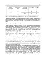
5.1 The effect of geometrical parameters on the mass flux distributions.
The effect of the internal diameter tube D on the mass flow rate for the steady-state
conditions is presented in Fig. 12. The mass flow rate rapidly increases with increasing
internal diameter tube
D.
Fig. 12. Mass flux rate
G
as a function of
H
q
with internal diameter tube D as the
parameter (HHCV).
The effect of the loop aspect ratio (height
H to breadth B) on the mass flow rate for the
steady-state conditions is presented in Fig. 13. The mass flow rate increases with increasing
H/B aspect ratio, due to the increasing gravitational driving force. The friction force is not
changed because the total length of the loop is assumed to be constant.
Fig. 13. Mass flux
G
as a function of
H
q
with aspect ratio H/B (height to breadth) as a
parameter (HHCV).
The effect of the length of the heated section
L
H
on the mass flow rate is shown in Fig. 18.
The length of FDR- friction dominant regime increases with increasing the length of the
heated section
L
H
.
The effect of the length of preheated section
L
HP
on the mass flux rate was obtained and is
demonstrated in Fig. 15. The mass flux rate increases with increasing length of preheated
section
L
HP
, due to the decreasing length of insulated section
51
s;s
.
Heat Transfer - Mathematical Modelling, Numerical Methods and Information Technology
490
Fig. 14. Mass flux
G
as a function of
H
q
with parameter L
H
(HHCV).
Fig. 15. Mass flux
G
as a function of
H
q
with parameter L
HP
(HHCV).
The effect of the length of the cooled section
L
C
on the mass flux rate was also investigated
and the results of calculations are presented in Fig. 16. The mass flux rate decreases with
increasing length of the cooled section
L
C
, due to the decreasing gravitational driving force
(
)
HΔ↓.
The effect of the length of precooled section
L
CP
on the mass flux rate is shown in Fig. 17.
The mass flux rate increases with decreasing length of precooled section
L
CP
due to the
decreasing length of insulated section
15
;ss and due to the increasing gravitational
driving force
(
)
HΔ↑. The decreasing value of the insulated two phase friction pressure
drop
15
2,
;
p
Friction
ss
dp
ds
⎛⎞
⎜⎟
⎝⎠
was caused by the decreasing length of insulated section
15
;ss
.
Natural Circulation in Single and Two Phase Thermosyphon Loop
with Conventional Tubes and Minichannels
491
Fig. 16. Mass flux
G
as a function of
H
q
with parameter L
C
(HHCV).
Fig. 17. Mass flux
G
as a function of
H
q
with L
CP
as a parameter (HHCV)
Fig. 18. Mass flux
G
as a function of
H
q
with parameter L (HHCV).
Heat Transfer - Mathematical Modelling, Numerical Methods and Information Technology
492
The effect of the total length of the loop L on the mass flow rate is shown in Fig. 18. The
mass flow rate decreases with increasing total length of the loop
L, due to the increasing
frictional pressure drop. The gravitational pressure drop is not changed because the
difference of height
HΔ
of the loop is constant.
5.2 The distributions of the heat transfer coefficient in flow boiling.
The heat transfer coefficient for flow boiling in minichannels was calculated using the
Mikielewicz formula Eq. (16) with some modifications concerning the two-phase flow in
minichannels, such as:
()
()
()
;
f
1
xx1Nx1
f
1
21R
z1
3
3
1
1
CONF
1
SM
⋅+−⋅
⎥
⎥
⎦
⎤
⎢
⎢
⎣
⎡
⋅⋅
⎟
⎟
⎠
⎞
⎜
⎜
⎝
⎛
−⋅+=
−
−
(22)
The heat transfer coefficient for flow boiling in minichannels was also calculated using the
Saitoh formula (Saitoh et al., 2007).
;hShEh
POOL
REF
SAITOH
TPB
⋅+⋅= (23)
where
()
;Pr
T
dq
d
207h
533.0
L
581.0
L
G
745.0
SATL
b
b
L
POOL
⋅
⎟
⎟
⎠
⎞
⎜
⎜
⎝
⎛
ρ
ρ
⋅
⎟
⎟
⎠
⎞
⎜
⎜
⎝
⎛
⋅λ
⋅
⋅
⎟
⎟
⎠
⎞
⎜
⎜
⎝
⎛
λ
⋅=
()
()()
⎪
⎪
⎩
⎪
⎪
⎨
⎧
⎟
⎠
⎞
⎜
⎝
⎛
λ
⋅⋅⋅
⎟
⎠
⎞
⎜
⎝
⎛
λ
⋅
=
TUR;
D
PrRe023.0
LAM;
D
Nu
h
L
4.0
L
5
4
L
L
LAM
REF
()
()
()
()
;
DG
Re;
DG
Re;
We1
X
1
1E
L
L
L
V
V
V
4.0
V
05.1
μ
⋅
=
μ
⋅
=
+
⎟
⎠
⎞
⎜
⎝
⎛
+=
−
()
()
(
)
()
[
]
()
;5.0
g
2
51.0d;
Re104.01
1
S;
DG
We
VL
b
4.1
TP
4
V
V
V
⎟
⎟
⎠
⎞
⎜
⎜
⎝
⎛
ρ−ρ⋅
σ⋅
⋅=
⋅⋅+
=
ρ⋅σ
⋅
=
−
()
()()
()
()
;
DG
Re;FReRe;x1GG;xGG
L
L
L
25.1
LTPLV
μ
⋅
=⋅=−⋅=⋅=
(
)
()
()
()
()
()
;
1000Re
1000Re
for
G
G
Re
C
C
X
;16C;046.0C
;
1000Re
1000Re
for
x
x1
X
V
L
5.0
V
L
5.0
L
V
5.0
V
L
4.0
G
5.0
V
L
LV
G
L
1.0
G
L
5.0
L
G
9.0
⎩
⎨
⎧
>
<
⎟
⎟
⎠
⎞
⎜
⎜
⎝
⎛
μ
μ
⋅
⎟
⎟
⎠
⎞
⎜
⎜
⎝
⎛
ρ
ρ
⋅
⎟
⎟
⎠
⎞
⎜
⎜
⎝
⎛
⋅⋅
⎟
⎟
⎠
⎞
⎜
⎜
⎝
⎛
=
==
⎩
⎨
⎧
>
>
⎟
⎟
⎠
⎞
⎜
⎜
⎝
⎛
μ
μ
⋅
⎟
⎟
⎠
⎞
⎜
⎜
⎝
⎛
ρ
ρ
⋅
⎟
⎠
⎞
⎜
⎝
⎛
−
=
−
The heat transfer coefficient for flow boiling in minichannels
TPB
h
versus heat flux
H
q
is
presented in Fig. 19.
Natural Circulation in Single and Two Phase Thermosyphon Loop
with Conventional Tubes and Minichannels
493
4x10
2
8x10
2
1x10
3
2x10
3
HHCV
MINICHANNELS: D=0.002 [m]
HEATER_CORRELATION: h
TPB
= f(q
H
)
MIKIELEWICZ (2007)
SAITOH (2007)
h
TPB
[ W / m
2
*K ]
q
H
[ W / m
2
]
Fig. 19. Heat transfer coefficient
TPB
α
as a function of
H
q
(HHCV).
5.3 The heat transfer coefficient for condensation.
The heat transfer coefficient in condensation for minichannels was calculated using the
general Mikielewicz formula Eq. (16). The term which describes nucleation process in that
formula was neglected.
The heat transfer coefficient for condensation in minichannels was also calculated using the
modified Tang formula (Tang et al., 2000)
()
()
()
;
x1
p
p
lnx
863.41
D
Nuh
836.0
CRIT
SAT
L
TANG
TPC
⎥
⎥
⎥
⎥
⎥
⎥
⎦
⎤
⎢
⎢
⎢
⎢
⎢
⎢
⎣
⎡
⎟
⎟
⎟
⎟
⎟
⎟
⎠
⎞
⎜
⎜
⎜
⎜
⎜
⎜
⎝
⎛
−
⎥
⎥
⎦
⎤
⎢
⎢
⎣
⎡
⎟
⎟
⎠
⎞
⎜
⎜
⎝
⎛
⋅−
⋅+⋅
⎟
⎟
⎠
⎞
⎜
⎜
⎝
⎛
λ
⋅= (24)
The heat transfer coefficient for condensation in minichannels
TPC
h
versus heat flux
C
q
is
presented in Fig. 21.
4x10
2
8x10
2
1,5x10
3
2,0x10
3
HHCV
MINICHANNELS: D=0.002 [m]
COOLER: h
TPC
=f(q
C
)
MIKIELEWICZ (2007)
TANG (2000)
h
TPC
[ W / m
2
*K ]
q
C
[ W / m
2
]
Fig. 20. Heat transfer coefficient
TPC
h
as a function of
C
q
(HHCV).