Vehicular Technologies Increasing Connectivity Part 5 pptx
Bạn đang xem bản rút gọn của tài liệu. Xem và tải ngay bản đầy đủ của tài liệu tại đây (580.83 KB, 30 trang )
Unlike in the IEEE802.11n system, in the 3GPP/LTE system, the time channel (SCME typical
to urban macro channel model (Baum et al., 2005)) varies too much due to higher mobility.
The orthogonality between training sequences in the 3GPP/LTE standard is thus based on
the transmission on each subcarrier of pilot symbols on one antenna while null symbols are
simultaneously sent on the other antennas. Therefore the LS channel estimates are calculated
only for
M
N
t
= 150 subcarriers and interpolation is performed to obtain an estimation for all
the modulated subcarriers.
system 802.11n 3GPP/LTE
Channel Model TGn (Erceg et al., 2004 ) SCME (Baum et al., 2005)
Sampling frequency (MHz) 20 15.36
Carrier frequency (GHz) 2.4 2
FFT size (N) 64 1024
OFDM symbol duration (μs) 4 71.35
Useful carrier (M) 52 600
Cyclic prefix (CP) 16 72
CP duration (μs) 0.80 4.69
MIMO scheme SDM double-Alamouti
MIMO rate (R
M
) 1 1/2
N
t
× N
r
2 ×2 4 ×2
Modulation QPSK 16QAM
Number of bit (m) 2 4
FEC conv code (7,133,171) turbo code (UMTS)
Coding Rate (R
c
) 1/2 1/3
Table 1 . Simulation Parameters
6.2 Simulation results
Perfect time and frequency synchronizations are assumed. Monte Carlo simulation results in
terms of bit error rate (BER) versus
E
b
N
0
are presented here for the different DFT based channel
estimation methods: classical DFT, DFT with pseudo inverse and DFT with truncated SVD.
The
E
b
N
0
value can be inferred from the signal to no ise ratio (SNR):
E
b
N
0
=
N
t
mR
c
R
M
.
σ
2
s
σ
2
n
=
N
t
mR
c
R
M
.SNR (26)
where σ
2
noise
and σ
2
x
represent the noise and signal variances respectively. R
c
, R
M
and m
represent the coding rate, the MIMO scheme rate and the modulation order respectively.
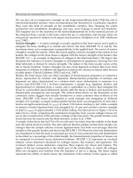
Fig.11 and Fig.12 show the performance results in terms of BER versus
E
b
N
0
for perfect, least
square (LS), classical DFT, DFT with pseudo inverse (DFT
− T
h
= CP)andDFTwith
truncated SVD for (several T
h
) channel estimation methods in 3GPP/LTE and 802.11n system
environments respectively.
In the context of 3GPP/LTE, the classical DFT based method presents p oorer results d ue to the
large number of null carriers at the border of the spectrum (424 among 1024). The conditional
number is as a consequence very high (CN
= 2.17 10
15
) and the impact of the “border
effect” is very important. For this reason, the DFT with pseudo inverse (DFT
− T
h
= CP =
111
DFT Based Channel Estimation Methods for MIMO-OFDM Systems
2 3 4 5 6 7 8 9 10
10
−4
10
−3
10
−2
10
−1
10
0
Eb/No (dB)
BER
PERFECT
DFT
DFT−Th43
DFT−Th44
DFT−Th45
DFT−Th46
DFT−Th55
DFT−Th72
LS
Th=44, 45, 46
Th=55
Th=CP=72
Th=43
Fig. 11. BER versus
E
b
N
0
for classical DFT, DFT pseudo inverse (T
h
= CP = 72) and DFT with
truncated SVD (T
h
= 55, T
h
= 46, T
h
= 45, T
h
= 44 and T
h
= 43) based channel estimation
methods in 3GPP context. N
t
= 4, N
r
= 2, N = 1024, CP = 72 and M = 600
2 4 6 8 10 12 14 16
10
−4
10
−3
10
−2
10
−1
10
0
Eb/No
BER
PERFECT
DFT
DFT−Th13
DFT−Th14
DFT−Th15
DFT−Th16
LS
Th=14, 15, 16
Th=13
Fig. 12. BER versus
E
b
N
0
for classical DFT, DFT pseudo inverse (T
h
= CP = 16) and DFT with
truncated SVD (T
h
= 15, T
h
= 14 and T
h
= 13) based channel estimation methods in 802.11n
context. N
t
= 2, N
r
= 2, N = 1024, CP = 72 and M = 600
112
Vehicular Technologies: Increasing Connectivity
72) can not greatly improve the accuracy of the estimated channel response. The classical
DFT and the DFT with pseudo inverse estimated channel responses are thus considerably
degraded compared to the LS one. The DFT with a truncated SVD technique and optimized
T
h
( T
h
=46,45,44) greatly enhances the accuracy of the estimated channel response by both
reducing the noise component and eliminating the impact of the “border effect” (up to 2dB
gain compared to LS). This last method presents an error floor when T
h
= 55duetothefact
that the “border effect” is still present and very bad results are obtained when T
h
is small
( T
h
= 43) due to the large loss of energy.
Comparatively, in the context of 802.11n, the number of null carriers is less important and the
classical DFT estimated channel response is not degraded even if it does not bring about any
improvement compared to the LS. The pseudo inverse technique completely eliminates the
“border effect” and thus its estimation (DFT
− T
h
= CP = 16) is already very reliable. DFT
with a truncated SVD channel estimation method does not provide any further performance
enhancement as the “border effect" is quite limited in this system configuration.
7. Conclusion
Several channel estimation methods have been investigated in this paper regarding the
MIMO-OFDM system environment. All these techniques are based on DFT and are so
processed through the time transform domain. The key system parameter, taken into account
here, is the number of null carriers at the spectrum extremities which are used on the vast
majority of multicarrier systems. Conditional number magnitude of the transform matrix has
been shown as a relevant metric to gauge the degradation on the estimation of the channel
response. The limit of the classical DFT and the DFT with pseudo inverse techniques has been
demonstrated by increasing the number of null subcarriers which directly generates a high
conditional number. The DFT with a truncated SVD technique has been finally proposed to
completely eliminate the impact of the null subcarriers whatever their number. A technique
which allows the determination of the truncation threshold for any MIMO-OFDM system is
also proposed. The truncated SVD calculation is constant and depends only on the system
parameters: the number and position of the modulated subcarriers, the cyclic prefix size and
the number of FFT points. All these parameters are predefined and are known at the receiver
side and it is thus possible to calculate the truncated SVD matrix in advance. Simulation
results in 802.11n and 3GPP/LTE contexts have illustrated that DFT with a truncated SVD
technique and optimized T
h
is very efficient and can be employed for any MIMO-OFDM
system.
8. References
Weinstein, S. B., and Ebert, P.M. (1971). Data transmission by frequency-division multiplexing
using Discret Fourier Transform. IEEE Trans. Commun., Vol. 19, Oct. 1971, pp.
628-634.
Telatar, I. E (1995). Capacity of Multi-antenna Gaussien Channel. ATT Bell Labs tech. memo,
Jun. 1995.
Alamouti, S. (1998). A simple tr ansmit diversity technique for wi reless communications, IEEE
J. Select. Areas Communication, Vol. 16, Oct. 1998, pp. 1451-1458.
Tarokh, V., Japharkhani, H., and Calderbank, A. R (1999). Space-time block codes from
orthogonal designs. IEEE Trans. Inform. Theory, Vol. 45, Jul. 1999, pp. 1456-1467.
113
DFT Based Channel Estimation Methods for MIMO-OFDM Systems
Boubaker, N., Letaief, K.B., and Murch, R.D. (2001). A low complexity multi-carrier
BLAST architecture for realizing high data rates over dispersive fading channels.
Proceedings of V TC 2001 Spring, 10.1109/VETECS.2001.944489, Taipei, Taiwan, May
2001.
Winters, J. H. (1987). On the capacity of radio communication systems with diversity in a
Rayleigh fading environment. IEEE J. Select. Areas Commun., Vol.5, June 1987, pp.
871-878.
Foschini, G. J (1996). Layered space-time architecture for wireless communication in a fading
environment when using multi-element antennas. Bell Labs Tech. J., Vol. 5, 1996, pp.
41-59.
Zhao, Y., and Huang, A. (1997). A Novel Channel Estimation Method for OFDM Mobile
Communication Systems Based on Pilot Signals and Transform-Domain. Proceedings
of IEEE 47th VTC, 10.1109/VETEC.1997.605966, Vol. 47, pp. 2089-2093, May 1997.
Morelli, M., and Mengali., U. (2001). A comparison of pilot-aided channel estimation methods
for OFDM systems. IEEE Transactions on Signal Processing, Vol. 49, Jan. 2001, pp.
3065-3073.
3GPP ( 2008), 3GPP TS 36.300 V8.4.0: E-UTRA and E-UTRAN overall description, Mar. 2008.
Doukopoulos, X.G., and Legouable, R. (2007). Robust Channel Estimation via FFT
Interpolation for Multicarrier Systems. Proceedings of IEEE 65th V TC-Spring,
10.1109/VETECS.2007.386, pages 1861-1865, 2007.
Van de Beek, J., Edfors, O., Sandell, M., Wilson, S. K. a nd Borjesson, P.O. (1995).
On Channel Estimation in OFDM Systems. Proceedings of IEEE VTC 1995,
10.1109/VETEC.1995.504981, pp. 815-819, Chicago, USA, Sept. 1995.
Auer, G. (2004). Channel Estimation for OFDM with Cyclic delay Diversity.
Proceedings of PIMRC 2004, 15th IEEE International Symposium on IEEE,
10.1109/PIMRC.2004.1368308, Vol. 3, pp. 1792-1796.
Draft-P802.11n-D2.0. IEEE P802.11nTM, Feb. 2007.
Le Saux, B., Helard, M., and Legouable, R. (2007). Robust Time Domaine Channel Estimation
for MIMO-OFDM Downlink System. Proceedings of MC-SS, Herrsching, Allemagne,
Vol. 1, pp 357-366, May 2007.
Baum, D.S., Hansen, J., and Salo J. (2005). An interim channel model for beyond-3g
systems: extending the 3gpp spatial channel model (smc). Proceedings of VTC,
10.1109/VETECS.2005.1543924, Vol. 5, pp 3132-3136, May 2005.
Moore, E. H. (1920). On the reciprocal of the general algebraic matrix. Bulletin of the American
Mathematical Society, Vol. 26, pp 394-395, 1920.
Penrose, R. (1955). A generalized inverse for matrices. Proceedings of the Cambridge
Philosophical Society 51, pp 406-413, 1955.
Yimin W. and al. (1991). Componentwise Condition Numbers for Generalized Matix Inversion
and Linear least sqares. AMS subject classification, 1991.
Erceg V. and al. (2004). TGn channel models. IEEE 802.11-03/940r4, May 2004.
114
Vehicular Technologies: Increasing Connectivity
7
Channels and Parameters Acquisition in
Cooperative OFDM Systems
D. Neves
1
, C. Ribeiro
1,2
, A. Silva
1
and A. Gameiro
1
1
University of Aveiro, Instituto de Telecomunicações,
2
Instituto Politécnico de Leiria
Portugal
1. Introduction
Cooperative techniques are promising solutions for cellular wireless systems to improve
system fairness, extend the coverage and increase the capacity. Antenna array schemes, also
referred as MIMO systems, exploit the benefits from the spatial diversity to enhance the link
reliability and achieve high throughput (Foschini & Gans, 1998). On the other hand,
orthogonal frequency division multiplexing (OFDM) is a simple technique to mitigate the
effects of inter-symbol interference in frequency selective channels (Laroia et al., 2004). The
integration of multiple antenna elements is in some situation unpractical especially in the
mobile terminals because of the size constraints, and the reduced spacing does not
guarantee decorrelation between the channels. An effective way to overcome these
limitations is generate a virtual antenna-array (VAA) in a multi-user and single antenna
devices environment, this is referred as cooperative diversity. The use of dedicated
terminals with relaying capabilities has been emerging as a promising key to expanded
coverage, system wide power savings and better immunity against signal fading (Liu, K. et
al., 2009).
A large number of cooperative techniques have been reported in the literature the potential
of cooperation in scenarios with single antennas. In what concerns channel estimation, some
works have discussed how the channel estimator designed to point-to-point systems
impacts on the performance of the relay-assisted (RA) systems and many cooperative
schemes consider that perfect channel state information (CSI) is available (Muhaidat &
Uysal, 2008), (Moco et al., 2009), (Teodoro et al., 2009), (Fouillot et al., 2010). Nevertheless, to
exploit the full potential of cooperative communication accurate estimates for the different
links are required. Although some work has evaluated the impact of the imperfect channel
estimation in cooperative schemes (Chen et al., 2009), (Fouillot et al., 2010), (Gedik & Uysal,
2009), (Hadizadeh & Muhaidat, 2010), (Han et al., 2009), (Ikki et al. 2010), (Muhaidat et al.,
2009), new techniques have been derived to address the specificities of such systems.
Channel estimation for cooperative communication depends on the employed relaying
protocol, e.g., decode and forward (DF) (Laneman et al., 2004) when the relay has the
capability to regenerate and re-encode the whole frame; amplify and forward (AF)
(Laneman et al., 2004) where only amplification takes place; and what we term equalize and
forward (EF) (Moco et al., 2010), (Teodoro et al., 2009), where more sophisticated filtering
operations are used.
Vehicular Technologies: Increasing Connectivity
116
In the case of DF, the effects of the BÆR (base station-relay node) channel are reflected in the
error rate of the decided frame and therefore the samples received at the destination only
depend on the RÆU (relay node–user terminal) channel. In this protocol the relaying node
are able to perform all the receiver’s processes including channel estimation and the point-
to-point estimators can be adopted in these cooperative systems. However the situation is
different with AF and Equalize-and-Forward (EF) which are protocols less complex than the
DF. In the former case (AF), BÆRÆU (base station-relay node-user terminal) channel is the
cascaded of the BÆR and RÆU channels, which has a larger delay spread than the
individual channels and additional noise introduced at the relay, this model has been
addressed in (Liu M. et al., 2009), (Ma et al., 2009), (Neves et al., 2009), (Wu & Patzold, 2009),
(Zhang et al., 2009), (Zhou et al., 2009).
Channel estimation process is an issue that impacts in the overall system complexity reason
why it is desirable use a low complex and optimal estimator as well. This tradeoff has been
achieved in (Ribeiro & Gameiro, 2008) where the MMSE in time domain (TD-MMSE) can
decrease the estimator complexity comparatively to the frequency domain implementation.
In (Neves et al., 2009) it is showed that under some considerations the TD-MMSE can
provide the cascaded channel estimate in a cooperative system. Also regarding the receiver
complexity (Wu & Patzold, 2009) proposed a criterion for the choice of the Wiener filter
length, pilot spacing and power. (Zhang et al., 2009) proposed a permutation pilot matrix to
eliminate inter-relay signals interference and such approach allows the use of the least
square estimator in the presence of frequency off-sets. Based on the non-Gaussian dual-hop
relay link nature (Zhou et al., 2009) proposed a first-order autoregressive channel model and
derived an estimator based on Kalman filter. In (Liu, M. et al., 2009) the authors propose an
estimator scheme to disintegrate the compound channel which implies insertion of pilots at
the relay, in the same way (Ma et al., 2009) developed an approach based on a known pilot
amplifying matrix sequence to improve the compound channel estimate taking into account
the interim channels estimate. To separately estimate BÆR and RÆU channels (Sheu &
Sheen. 2010) proposed an iterative channel estimator based on the expectation
maximization. Regarding that the BÆR and RÆU links are independent and point-to-point
links (Xing et al. 2010) investigated a transceiver scheme that jointly design the relay
forward matrix and the destination equalizer which minimize the MSE. Concerning the two-
way relay (Wang et al. 2010) proposed an estimator based on new training strategy to jointly
estimate the channels and frequency offset. For MIMO relay channels (Pang et al. 2010)
derived the linear mean square error estimator and optimal training sequences to minimize
the MSE. However to the best of our knowledge channel estimation for EF protocol that use
Alamouti coding from the base station (BS) to relay node (RN), equalizes, amplifies the
signals and then forward it to the UT has not been considered from the channel estimation
point of view in the literature. Such a scenario is of practical importance in the downlink of
cellular systems since the BS has less constraints than user terminals (or terminals acting as
relays) in what concerns antenna integration, and therefore it is appealing to consider the
use of multiple antennas at the BS improving through the diversity achieved the
performance in the BÆR link.
However due to the Alamouti coding–decoding operations, the channel BÆRÆ
U is not just
the cascade of the BÆR and RÆU channels, but a more complex channel. The channel
estimator at the UT needs therefore to estimate this equivalent channel in order to perform
the equalization. The derivation of proper channel estimator for this scenario is the objective
of this chapter. We analyze the requirements in terms of channels and parameters estimation
Channels and Parameters Acquisition in Cooperative OFDM Systems
117
to obtain optimal equalization. We evaluate the sensitivity of required parameters in the
performance of the system and devise scheme to make these parameters available at the
destination. We consider a scenario with a multiple antenna BS employing the EF protocol,
and propose a time domain pilot–based scheme (Neves, et al. 2010) to estimate the channel
impulse response. The BÆR channels are estimated at the RN and the information about the
equivalent channel inserted in the pilot positions. At the user terminal (UT) the TD-MMSE
estimator, estimates the equivalent channel from the source to destination, taking into
account the Alamouti equalization performed at the RN. The estimator scheme we consider
operates in time domain because of the reduced complexity when compared against its
implementation in frequency domain, e.g. (Ribeiro & Gameiro, 2008).
The remainder of this chapter is organized as follows. In Section 2, we present the scenario
description, the relaying protocol used in this work and the corresponding block diagram of
the proposed scheme. The mathematical description involving the transmission in our
scheme is presented in Section 3. In Section 4, we present the channel estimation issues such
as the estimator method used in this work and the channels and parameters estimates to be
assess at the RN or UT. The results in terms of BER and MSE are presented in Section 5.
Finally, the conclusion is pointed out in Section 6.
2. System model
2.1 Definition
Throughout the text index n and k denote time and frequency domain variables,
respectively. Complex conjugate and the Hermitian transposition are denoted by
()
*
. and
()
H
⋅ , respectively.
{
}
Ε
⋅ and
(
)
∗
correspondently denote the statistical expectation and the
convolution operator.
(
)
σ
N
2
,m refers to a complex Gaussian random variable with mean
m and variance
σ
2
.
(
)
⋅
dia
g
stands for diagonal matrix,
⋅
denotes absolute value and
Q
I
denotes the identity matrix of size
Q . Regular small letters denote variables in frequency
domain while boldface small and capital letters denote matrices and vectors, respectively in
frequency domain as well. Variables, vectors or matrixes in time domain are denoted by
(
)
~ . All estimates are denoted by
(
)
^ .
2.2 Channel model
The OFDM symbol =xd+p where p corresponds to the pilots which are multiplexed
with data
d subcarriers. The element
()
k
x of the OFDM symbol vector is transmitted over a
channel which the discrete impulse response is given by:
()
()
1
0
,
G
lg
n
g
hn
β
δτ
−
=
=−
∑
(1.1)
where G is total number of paths,
g
β
and
g
τ
are the complex amplitude and delay of the
gth path, respectively.
g
β
is modelled as wide-sense stationary uncorrelated scattering
(WSSUS) process. The
gth path has a variance
2
g
σ
which is determined by the power delay
profile and satisfies
1
2
0
1
G
g
g
σ
−
=
=
∑
. Although the channel is time-variant we assume it is
constant during one OFDM symbol interval and its time dependence is not present in
notation for simplicity.
Vehicular Technologies: Increasing Connectivity
118
2.3 Scenario description
The studied scenario, depicted in Fig. 1, corresponds to the proposed RA schemes for
downlink OFDM-based system. The BS and the RN are equipped with
M
and L antennas,
respectively. The BS is a double antenna array and the UT is equipped with a single
antenna. Throughout this chapter we analyze two RA schemes: the RN as a single antenna
or an array terminal. These scenarios are referred as 1ML
×
× schemes.
Antenna
Array
Single
Antenna
BS
RN
Direct Channel
Relay Channel
UT
bu
:
m
h
br
:
ml
h
ru
:
l
h
Single Antenna
/Array
brml
h
bum
h
rul
h
B Æ U
R Æ U
B Æ R
Fig. 1. Proposed RA scenario
The following channels per k subcarrier are involved in this scheme:
•
1M × MISO channel between the BS and UT (BÆU):
()
bu ,
, 1,2
mk
hm=
•
1L × MISO channel between the RN and UT (RÆU):
()
ru ,
, 1,2
lk
hl=
•
M
L× channel between the BS and RN (BÆR):
()
br ,
, 1,2 and 1,2
ml k
hm l==
All the channels are assumed to exhibit Rayleigh fading, and since the RN and UT are
mobile the Doppler’s effect is considered in all channels and the power transmitted by the
BS is equally allocated between the two antennas.
2.4 The Equalize-and-Forward (EF) relaying protocol
For the single antenna relay scenario, the amplify-and-forward protocol studied in (Moco et
al., 2010) is equivalent to the RA EF protocol considered here. However, if the signal at the
relay is collected by two antennas, doing just a simple amplify-and-forward it is not the best
strategy. We need to perform some kind of equalization at the RN to combine the received
signals before re-transmission. Since we assume the relay is half-duplex, the communication
cycle for the aforementioned cooperative scheme requires two phases:
Phase I: the BS broadcasts its own data to the UT and RN, which does not transmit data
during this stage.
Phase II: while the BS is idle, the RN retransmits to the UT the equalized signal which was
received from the BS in phase I. The UT terminal receives the signal from the RN and after
reception is complete, combines it with the signal received in phase I from the BS, and
provides estimates of the information symbols.
Channels and Parameters Acquisition in Cooperative OFDM Systems
119
2.5 The cooperative system
Fig. 2 shows the corresponding block diagram of the scenario depicted in Fig. 1, with
indication of the signals at the different points. The superscripts (1) and (2) denote the first
and the second phase of the EF protocol, respectively. In the different variables used, the
subscripts
u
, r and b mean that these variables are related to the UT, RN and BS,
respectively.
RN
Estimator
1
0
BS
UT
Hard
Decision
1
0
Estimator
Data
Combiner
()
()
1
k
x
()
()
1
k
x
()
(
)
2
k
x
()
(
)
2
u, k
y
()
(
)
1
r, k
s
Soft-Decision
+
+
+
()
(
)
2
u, k
s
()
(
)
1
u, k
s
Estimator
()
ru ,lk
h
()
() ()
(
)
121
u
u,
,0,
k
n
σ
N
()
() ()
(
)
121
r
r,
,0,
k
n
σ
N
()
() ()
(
)
222
u
u,
,0,
k
n
σ
N
()
br ,ml k
h
()
bu ,mk
h
SFBC
Mapping
Soft-Decision
Soft-Decision
Fig. 2. The corresponding block diagram of the 1ML
×
× RA scenario
Let
(
)
01
1
d
T
N
d d d=−d " be the symbol sequence to be transmitted where
d
N is the
number of data symbols, then for k even the SFBC (Teodoro el al., 2009) mapping rule is
defined in Table 1. The symbols
()
k
d are assumed to have unit average energy, i.e.
()
2
1,
k
d k=∀
, and therefore the factor
12
used in the mapping, is to ensure that the total
energy transmitted by the two antennas per subcarrier is normalized to
1
.
Subcarrier Antenna 1 Antenna 2
k
()
2
k
d
()
1
2
k
d
∗
+
−
1k
+
()
1
2
k
d
+
()
2
k
d
∗
Table 1. Two transmit antenna SFBC mapping
The pilot symbols are multiplexed with data and the BS broadcasts the information
()
()
1
k
x
(data and pilot) to the RN and UT. This processing corresponds to the phase I of the EF relay
protocol. At the UT, the direct channels are estimated and the data are SFBC de-mapped and
equalized. These two operations are referred as soft-decision which the result is the soft-
decision variable, in this case,
()
()
1
u, k
s
. At the RN, pilots and data are separated; based on
pilots, the channels BÆR are estimated and the soft-decision is performed. The result is the
soft-decision variable
()
()
1
r, k
s
. Then, the new pilot symbols are multiplexed in
()
()
1
r, k
s
and the
Vehicular Technologies: Increasing Connectivity
120
information
()
()
2
k
x is transmitted / forwarded to the UT via RÆU channel. This second
transmission corresponds to the phase II of the EF protocol. At the final destination, the
required channel is estimated and the soft-decision is performed in order to obtain the soft-
decision variable
()
()
2
u, k
s . After the phase II the UT has the soft-variable provided by both the
BS and RN. These variables are combined and hard-decoded.
3. Mathematical description of the proposed cooperative scheme
The mathematical description for transmit and receive processing is described in this
section. As this work is focused on channel estimation, this scheme is designed in order to
be capable to provide all the channels and parameters that the equalization requires in both
phases of the relaying protocol.
3.1 Phase I
During the first phase the information is broadcasted by the BS. The frequency domain (FD)
signals received at the UT in data-subcarriers k and
+
1k are given by
()
()
()() ()()
()
()
()
()
()
() () ( ) ( )
()
()
()
++
++++
⎧
=−+
⎪
⎪
⎨
⎪
=++
⎪
⎩
11
*
u, bu1, bu2, 1 1 u,
11
*
u,1 bu2, bu1,1 1 u,1
1
2
,
1
2
kkkkkk
kkkkkk
yhdhdn
yhdhdn
(3.1)
where
()
()
1
u, k
n
is the additive white Gaussian noise with zero mean unit variance
()
σ
21
u
and for
1,2m =
,
()
bu ,mk
h
represent the channels between the BS and the UT terminal.
The FD signals received at the RN in data-subcarriers
k and 1k
+
are expressed by:
()
()
() () ( ) ( )
()
()
()
()
()
() () ( ) ( )
()
()
()
++
++++
⎧
=−+
⎪
⎪
=
⎨
⎪
=++
⎪
⎩
11
*
r , br1 , br2 , 1 1 r,
11
*
r,1 br2, br1,1 1 r,1
1
2
,1,2
1
2
lk lk k lk k k
lk lk k lk k k
yhdhdn
l
yhdhdn
(3.2)
where
()
br ,ml k
h represent the channels between the antenna
m
of the BS and antenna l of the
RN terminal and
()
()
1
r, k
n is the additive white Gaussian noise with zero mean unit variance
()
21
r
σ
.
Since the data are SFBC mapped at the BS the SFBC de-mapping at the terminals RN and UT
also includes the MRC (maximum ration combining) equalization which coefficients are
functions dependent on the channels estimates. It is widely known that in the OFDM
systems the subcarrier separation is significantly lower than the coherence bandwidth of the
channel. Accordingly, the fading in two adjacent subcarriers can be considered flat and
without loss of generality we can assume for generic channel
() ( )
1kk
hh
+
=
. Thus, in phase I
the soft-decision variables at the UT follow the expression.
()
()
() ()
()
() ( )
()
()
()
() ()
()
() ( )
()
+
++
⎧
=+
⎪
⎨
=− +
⎪
⎩
11*1
*
u, bu1, u, bu2, u, 1
1*11
*
u,1 bu2,u, bu1,u,1
,
kkkkk
kkkkk
sgygy
sgygy
(3.3)
Channels and Parameters Acquisition in Cooperative OFDM Systems
121
where the equalization coefficients for 1,2m
=
are given by
() ()
σ
=
2
u
bu , bu ,
ˆ
2
mk mk
gh . After
some mathematical manipulation, these soft-decision variables may be expressed as:
()
()
() ()
()
()
()
()
()
()
()
()
()()
()
()
()
()
()
()
*
bu1, bu2,
111*
u, bu, u, u,
*
bu1, 1 bu2, 1
111*
u, 1 bu, 1 1 u, 1 u, 1
ˆˆ
22
,
ˆˆ
22
kk
kkk k k
kk
kkk k k
hh
sdn n
hh
sdn n
++
+++ + +
⎧
⎪
=Γ + +
⎪
⎨
⎪
=Γ + −
⎪
⎩
(3.4)
where
=
Γ=
∑
2
2
bu bu
1
1
ˆ
2
m
m
h .
The soft-decision variables should be kept in a buffer, waiting for the information to be
provided by the RN in the second phase of the protocol. The mathematical formulation of
the next phase varies according to the number of antennas at the RN, i.e.
L , and these cases
are separately presented in the next sub-sections.
3.2 Phase II
3.2.1 RN equipped with a single antenna
The FD soft-decision variables at the RN in data-subcarriers k and 1k
+
are expressed by:
()
()
()
()
()
()
()
()
()
()
()
()
+
++
⎧
=+
⎪
⎨
=− +
⎪
⎩
11*1
*
br11 br21
r, r1, r1, 1
1*11
*
br21 br11
r, 1 r1, r1, 1
,
kkk
kkk
sgy gy
sgygy
(3.5)
where the equalization coefficient are given by
() ()
(
)
=
br , br ,
ˆ
2
ml k ml k
gh , for
1,2m
=
and 1l = .
After some mathematical manipulation, these soft-decision variables are given by:
()
()
() ()
()
()
()
()
()
()
()
()
()()
()
()
()
()
()
()
*
br11, br21,
111*
r, br, r, r,
*
br11, 1 br21, 1
111*
r, 1 br, 1 1 r, 1 r, 1
ˆˆ
22
,
ˆˆ
22
kk
kkk k k
kk
kkk k k
hh
sd n n
hh
sd n n
++
+++ + +
⎧
⎪
=Γ + +
⎪
⎨
⎪
=Γ + −
⎪
⎩
(3.6)
where
()
=
Γ=
∑
2
2
br
br,
1
1
ˆ
2
ml
k
m
h .
In order to transmit a unit power signal the RN normalizes the expression in (3.6) by
considering the normalization factor
()
k
α
which is given by:
()
() ()
()
α
σ
=
Γ+Γ
21
2
r
br, br ,
1
k
kk
(3.7)
During the phase II, the normalized soft-decision variable is sent via the second hop of the
relay channel R
ÆU. The FD signal received at the UT per k subcarrier is expressed
according to:
Vehicular Technologies: Increasing Connectivity
122
()
()
() ()
()
() ()
()
21 2
u, r, ru, u,
,
kkkk k
yshn
α
=+ (3.8)
where
()
()
2
u, k
n
is the additive white Gaussian noise which is zero mean and has unit variance
()
σ
22
u
.
The signal in (3.8) is equalized using the coefficients
() () () ()
(
)
α
σ
=Γ
2
t
ru , br, ru ,
ˆ
lk k k k
gh which after
some mathematical manipulation is given by:
()
()
() ()
()
() () ()
()
()
()
() () ()
() ()
()
() ()
()
()
αα
σσ
α
σ
=Γ +Γ
Γ+
2
*
ru1,
ru1,
22
22
u, br, u,
22
2
1*1
2*
br, ru , br11, r, br21, r ,
2
ˆ
ˆ
1
ˆˆˆ
+ .
2
k
k
kkk kkk k
tt
k k lk kk kk
t
h
h
sdn
hhnhn
(3.9)
The equalization coefficient
()
ru1, k
g is a function dependent on the channel estimate
()
ru1,
ˆ
k
h
and the variance of the total noise. Moreover, the statistics of the total noise is conditioned to
the channel realization
()
br ,
ˆ
ml k
h . Therefore the variance of the total noise can be computed as
conditioned to these channel realizations or averaged over all the channel realizations. We
denote by
()
()
ru1
2
t,hk
σ
the noise variance conditioned to the specific channel realization per k
subcarrier and by
σ
2
t
the unconditioned noise variance. The noise variance of the total noise
conditioned to channel realizations is found to be:
()
()
() () ()
() ()
ru ,
2
22 21
22
uu
br, ru1,
t,
.
k
kk k
h
h
σα σσ
=Γ + (3.10)
3.2.2 RN equipped with a double antenna array
When the array is equipped with two antennas the soft-decision variables are expressed by:
()
()
() ()
()
() ( )
()
()
()
()
() ()
()
() ( )
()
()
2
111*
*
r, br1, r, br2, r, 1
1
2
11*1
r,1 br2,r, br1,r,1
1
, 1,2
k lklk lklk
l
k lklk lklk
l
sgygy
l
sgygy
+
=
++
=
⎧
=+
⎪
⎪
=
⎨
⎪
=− +
⎪
⎩
∑
∑
(3.11)
where the equalization coefficients are expressed by
() ()
(
)
=
br , br ,
ˆ
2
ml k ml k
gh
.
The RN transmits to the UT a unit power signal following the normalization factor in (3.7).
However, in this scenario
()
Γ
br, k
is expressed by
() ()
==
Γ=
∑∑
22
2
br, br ,
11
1
ˆ
2
kmlk
ml
h . The FD signals
received at the UT are given by:
()
()
() () ()
()
()()()
()
()
()
()
()
()
() () ()
()
()()()
()
()
()
()
αα
αα
++ +
+++++
⎧
=− +
⎪
⎪
⎨
⎪
=+ +
⎪
⎩
211*2
*
u, ru1, , ru2,1 1r,1 u,
21*12
*
u, 1 ru2, r , ru1, 1 1 r, 1 u, 1
1
2
,
1
2
kkkrkkkkk
kkkkkkkk
yhsh sn
yhshsn
(3.12)
Channels and Parameters Acquisition in Cooperative OFDM Systems
123
where
()
ru ,
ˆ
lk
h represent the channels between the RN and the UT terminal. The soft-decision
variables found at the UT in phase II are expressed by:
()
()
()
()
()
()
()
()
()
()
()
()
+
++
⎧
=+
⎪
⎨
=− +
⎪
⎩
22*2
*
ru1 ru2
u, u, u, 1
2*22
*
ru2 ru1
u, 1 u, u, 1
,
kkk
kkk
sgygy
sgygy
(3.13)
where the equalization coefficients are given by
() () () ()
(
)
α
σ
=Γ
2
t
ru , br, ru ,
ˆ
2
lk k k lk
gh, for 1,2l = .
In this scenario the soft-decision variables also depend on the variance of the total noise
σ
2
t
which conditioned to the channel specific realization can be calculated from (3.12) and is
expressed by,
()
() () ()
() ()
ru ,
21 22
22
t, r u
br, ru,
lk
h
kkk
σα σσ
=ΓΓ + (3.14)
where
() ()
=
Γ=
∑
2
2
ru, ru ,
1
1
ˆ
2
klk
l
h .
The UT combines the signals received from the RN and the BS. By performing this
combining the diversity of the relay path is exploited. This processing is conducted by
taking into account
()
()
()
()
+
12
u, u,kk
ss with ensure and MRC combining. The result corresponds to
the variable to be hard-decoded.
4. Channel estimation
4.1 Time Domain Minimum Mean Square Error (TD-MMSE) estimator
The TD-MMSE (Ribeiro & Gameiro, 2008) corresponds to the version of the MMSE estimator
which was originally implemented in FD. This estimator comprises the least square (LS)
estimation and the MMSE filtering, both processed in time domain (TD). The TD-MMSE is a
pilot-aided estimator, i.e. the channel estimation is not performed blindly. It is based on pilot
symbols which are transmitted by the source and are known at destination.
The pilot subcarriers convey these symbols that are multiplexed with data subcarriers
according to a pattern, Fig. 3, where
f
N and
t
N correspond to distance between two
consecutives pilots in frequency and in time, respectively. N is the number of OFDM
symbols and
c
N is the number of subcarriers. The pattern presented in Fig. 3 is adopted
during the transmission stages of the envisioned cooperative scheme.
It is usual the pilot symbols assume a unitary value and be constant during an OFDM
symbol transmission. Thus, at k subcarrier the element
p
of the vector p may be expressed
by a pulse train equispaced by
f
N with unitary amplitude. The corresponding expression
in TD is also given by a pulse train with elements in the instants
(
)
c
f
nmNN− , for
{
}
0; 1
f
mN∈−, according to the following expression.
()
()
()
()
1
1
00
1
.
ff
fcf
NN
F
kn
kmN nmN N
mm
f
p p
N
δδ
−
−
−−
==
=←⎯⎯→=
∑∑
(4.1)
The transmitted signal is made-up of data and pilot components. Consequently, at the
receiver side the component of the received signal in TD is given by the expression in (4.2).
Vehicular Technologies: Increasing Connectivity
124
() () ( )
()
()
1
1
00
1
,
f
c
cf
N
N
nknk n
nmN N
km
f
y
hd h n
N
−
−
−
−
==
=+ +
∑∑
(4.1)
where
()
n
n
is the complex white Gaussian noise.
N
t
N
c
Frequency
Time
: Data subcarriers
: Pilot Subcarriers: antenna 1
: Subcarriers
N
f
N
c
: Pilot Subcarriers: antenna 2
N
N
: OFDM Symbols
Fig. 3. Pilot pattern
In order to perform the LS estimation in TD, i.e. TD-LS, the received signal is convolved
with the TD pilot symbols
()
n
p
. This convolution corresponds to multiply by 1 the
subcarriers at frequencies
f
N as by design these are the positions reserved to the pilots thus
the data component in the received signal vanishes. The resulting CIR estimate
ˆ
LS
h
is made-
up of
f
N replicas of the CIR separated by
c
f
NN.
()()
11
LS
00
CIR Noise
ˆ
, 0,1, , 1.
ff
cf cf
NN
c
nmN N nmN N
mm
f
N
hh n n
N
−−
−−
==
=
+=−
∑∑
"
(4.3)
Besides to estimate the CIR the TD-MMSE in (Ribeiro & Gameiro, 2008) can estimate the
noise variance as well. It corresponds to an essential requirement when the UT has no
knowledge of this parameter. Since we know that the CIR energy is limited to the number
of taps, or the set of the taps
{
}
G , the noise variance estimate
2
ˆ
n
σ
can be calculated by take
into account the samples out of the number of taps, i.e.
{
}
nG∉ and by averaging the
number of OFDM symbols N . Thus
2
ˆ
n
σ
is given by:
()
()
{}
2
2
1
ˆ
ˆ
.
N
cf
n
n
inG
cf
NN
h
NN GN
σ
=∉
=
⎡⎤
−
⎣⎦
∑∑
(4.4)
The MMSE filter can improve the LS estimates by reducing its noise variance. The TD-
MMSE filter corresponds to a diagonal matrix with non-zero elements according to the
number of taps, i.e. G , thus it can be implemented simultaneously with the TD-LS estimator
and this operation simplifies the estimator implementation. The MMSE filter implemented
by the
()
(
)
c
f
c
f
NN NN× matrix and for a generic channel h it is expressed by:
Channels and Parameters Acquisition in Cooperative OFDM Systems
125
1
ˆˆˆ
,
,
MMSE h
hh hh
−
=WRR
(4.5)
where
ˆˆ
hh
R
is the
(
)
(
)
c
f
c
f
NN NN× filter input correlation matrix,
{
}
ˆˆ
H
Ε hh
, which is given
by
2
cf
nN N
hh
σ
+RI
, and
ˆ
hh
R
is the
(
)
(
)
c
f
c
f
NN NN× filter input-output cross-correlation
matrix,
{
}
ˆ
H
Ε hh
, which is given by
(
)
σσ σ
−
⎡⎤
=
⎣⎦
""
22 2
01 1
diag , , , , 0, , 0
G
hh
R
.
4.2 Channels and parameters estimates
According to the scenario previously presented, there are channels which correspond to
point-to-point links:
()
bu ,mk
h
and
()
br ,ml k
h
. Therefore, these channels can be estimated by using
conventional estimators. However, for the RN
ÆUT links, and since the EF protocol is used,
it is necessary to estimate a version of
()
ru ,lk
h
, which depends on
()
k
α
and
()
k
Γ
, the
equivalent channel
() () ()
α
=
Γ
eq
ru ,kk lk
hh
. Note that the UT has no knowledge of
()
k
α
and
()
k
Γ
.
These factors are dependent on
()
br ,ml k
h
which the UT has no knowledge as well. However,
the channels
()
br ,ml k
h
are estimated at the RN, and based on that,
() ()
kk
α
Γ
is calculated.
Therefore, we propose to transmit the factor
() ()
kk
α
Γ
at the pilot subcarriers as pilots.
Consequently, the new pilots are no longer constant and that may compromise the
conventional TD-MMSE performance, since this estimator was designed in time domain
assuming the pilots are unitary with constant values at the destination. Although our
approach enables the destination had knowledge of the non-constant pilot
() ()
(
)
kk
α
Γ , the
result of the convolution between the received signal and these pilots, would result in the
overlapped replicas of CIR, according to the Fig. 4.
overlap
Convolution by the pulse
train in TD
Equispaced pilots with non-
constant and undesirable
samples between them
Data samples overlap with
pilot and undesirable samples
As result:
The replicas of CIR
are spread
Frequency Domain
Time Domain
Equispaced pilots with
non-constant values
Time Domain
…
…
…
Pilot
Data
⇔
⇐
…… …
f
N
c
f
N
N
c
f
N
N
c
f
N
N
c
f
N
N
+
+
Fig. 4. Pilots with non-constant values result in the overlapped replicas of the CIR
However, the
()
k
α
expressions depend on the noise variance
()
σ
21
r
and the product
() ()
α
Γ
kk
tends to one for a high SNR value, according to (4.6). The same equation also suggests that
the factor
() ()
α
Γ
kk
varies exponentially according to the SNR, as depicted in Fig. 5 for 1L = .
() ()
() ()
()
()
()
()
α
σ
⎛⎞
⎛⎞
⎜⎟
⎜⎟
Γ
=Γ=Γ≅
⎜⎟
⎜⎟
⎜⎟
Γ+
⎜⎟
Γ+Γ
⎝⎠
⎝⎠
br, br,
2
21
2
br
,
br, br, r
11
1.
0
kk k k
k
kk
(4.6)
Vehicular Technologies: Increasing Connectivity
126
0 2 4 6 8 10 12 14 16 18 20
0.75
0.8
0.85
0.9
0.95
1
αΓ
SNR (dB)
αΓ
Fig. 5.
() ()
kk
α
Γ vs. SNR
Other behaviour of the factor
() ()
α
Γ
kk
can be demonstrated in terms of SNR and subcarriers,
as presented in Fig. 6. These plots show that in the first case,
i.e. SNR 20dB
=
, the
() ()
kk
α
Γ
factor presents the amplitude close to
1 with some negligible fluctuation. However, in the
second case, SNR 2dB
=
, the result is likely different to the previous one: the
() ()
α
Γ
kk
factor
presents an amplitude also close to
1 but the fluctuation is not negligible.
0 20 40 60 80 100 120
0.3
0.6
0.9
1.2
Subcarrier
Amplitude
αΓ
: 2 x2x1 SNR=2dB
αΓ
: 2x2x1, SNR=20dB
αΓ
: 2x1x1, SNR=2dB
αΓ
: 2x1x1, SNR=20dB
Fig. 6.
() ()
α
Γ
kk
per subcarriers
The results in Fig. 6 emphasize that transmit the factor
() ()
α
Γ
kk
in the pilot subcarriers may
degrade the estimator performance and the causes are:
1.
Pilots with some fluctuation in amplitude:
Channels and Parameters Acquisition in Cooperative OFDM Systems
127
• As the amplitude of the pilots at the destination are constant and equal to one, the
result of the estimation is a spread of the replicas of the CIR.
2.
Decreasing the amplitude of the pilots:
• The SNR of the pilots is decreased as well.
3. The MMSE filter depends on the statistics of the channel B
Æ
R
Despite we are considering the TD-MMSE estimator in our analysis, the causes presented
previously degrade the performance of any other estimator scheme as well. In order to
quantify how these effects can degrade the estimator performance we evaluated the impact
of both of them, separately, in a SISO system, since the B
ÆR and RÆU channels correspond
to point-to-point links.
First, we evaluate the case when the pilots have some fluctuation in amplitude. We consider
that the pilots (originally with unit amplitude) had their amplitude disturbed by a noise
with zero mean and variance equal to
() ()
{
}
2
2
kk
1
αΓ
σ=Ε −αΓ
,
2
α
Γ
σ
quantifies how far the
factor
() ()
α
Γ
kk
would be from the pilots with unitary amplitude. We can express
2
αΓ
σ as:
() ()
()
{
}
() ()
{}
2
2
kk kk
12.
αΓ
σ =+ΕαΓ −ΕαΓ (4.7)
Therefore, the pilots are no longer constant and unitary. They have some fluctuation in
amplitude which depend on
() ()
α
Γ
kk
and they are equal to
2
p 1z
αΓ
σ
=
+ , where z has a
normal distribution with zero mean and power
2
α
Γ
σ
. The performance of a SISO system
which the pilots correspond to
2
p
α
Γ
σ
is shown in Fig. 7 (dash line). For reference, we also
include the SISO performance for unit pilots,
1
p
. Since we are focus on the degradation of
the estimator performance, the results are presented in terms of the normalized mean square
error (MSE) and
0b
EN, where
b
E corresponds to the energy per bit received at UT and
0
N
is the power spectrum density of the total noise which affects the information conveying
signals. The normalized MSE for a generic channel
h is given by:
{
}
{}
2
2
ˆ
MSE .
h
hh
h
Ε−
=
Ε
(4.8)
For low values of SNR,
[
]
04
−
, the major difference in performance between the two results
is approximately 0.5dB , which is not a noticeable degradation and the estimator
performance is not compromised.
The second effect to be evaluated is the decreasing of the amplitude of the transmitted pilot.
In order to evaluate this effect we also consider a SISO system, for which the transmitted
pilots assume different constant values, and we consider different values of the factor
() ()
α
Γ
kk
as pilot. The normalized MSE is given by (4.9). The result is shown in Fig. 8 and for
reference we include the SISO performance for unit pilots,
1
p
, as well.
{
}
{}
2
eq eq
eq
2
eq
ˆ
MSE .
hh
h
Ε−
=
Ε
(4.9)
Vehicular Technologies: Increasing Connectivity
128
0 2 4 6 8 10 12
-27
-24
-21
-18
-15
-12
MSE (dB)
E
b
/N
0
(dB)
SISO, p
σ
2
αΓ
SISO, p
1
Fig. 7. Channel estimation MSE performance
0 2 4 6 8 10 12
-27
-24
-21
-18
-15
-12
MSE (dB)
E
b
/N
0
(dB)
αΓ
= 7.388e-001
αΓ
= 8.730e-001
αΓ
= 9.306e-001
p
1
Fig. 8. Channel estimation MSE performance
The results show a constant shift in the MSE when the amplitude of the pilots is not unitary.
The shift presents in all results is not a real degradation. It is caused by the normalization
present in the MSE in (4.9). In fact, assuming a MSE without normalization the results are all
the same.
Transmit the factor
() ()
α
Γ
kk
as pilot does not bring any noticeable degradation in the TD-
MMSE performance comparing to transmitting unitary pilots. The major degradation occurs
only when the pilots have some fluctuation in amplitude, as shown in Fig. 7, and solely for
low SNR values.
The conventional MMSE filter in (4.5) is implemented to improve a channel estimate
ˆ
h
when the required channel corresponds to h . However, according to our cooperative
Channels and Parameters Acquisition in Cooperative OFDM Systems
129
scheme, we need estimate an equivalent channel
() () ()
eq
ru ,
kk lk
hh
=
αΓ . Since the factor
j
αΓ does
not depend on
ru
h
, the MMSE filter input correlation matrix for the channel
eq
h
, referred
eq eq
ˆˆ
hh
R
, is expressed by
{
}
j
m
j
m
{}
ru ru
2
eq eq
ˆˆ
cf
H
nN N
hh
αΓαΓ
Ε= +σhh R R I
while the filter input-output
cross-correlation, referred as
eq eq
ˆ
hh
R
, is given by
{
}
j
m
j
m
{}
ru ru
eq eq
ˆ
H
hh
αΓαΓ
Ε=hh R R
, both
eq eq
ˆˆ
hh
R
and
eq eq
ˆ
hh
R
are
()
(
)
c
f
c
f
NN NN× matrices. Thus the MMSE filter, when
eq
h
is required, may
be express as:
j
m
j
m
{}
j
m
j
m
{}
eq ru ru ru ru
1
2
MMSE,
.
cf
nN N
hhhhh
αΓαΓ αΓα
−
Γ
⎛⎞
=+σ
⎜⎟
⎝⎠
WRRRRI
(4.10)
As we shown previously in (4.6) the factor
() ()
α
Γ
kk
tends to one for high values of SNR and
examining (4.10), which depends on
j
m
α
Γ , it is clear that (4.10) tends to (4.5) for high values
of SNR as well. In order to show that several simulation were performed by taking into
account
eq eq
ˆˆ
hh
R
and the noise variance
(
)
21
r
σ
. According to Fig. 9 the results show that the
maximum value in the
eq eq
ˆˆ
hh
R
matrix is close to 40dB
−
for high values of the noise variance.
0 0.5 1 1.5 2
-85
-80
-75
-70
-65
-60
-55
-50
-45
-40
σ
2
n
Max (dB)
Maximum Value in the Cross-correlation Matrix
Fig. 9. Maximum value in the correlation matrix vs. noise variance
According to the results in Fig. 7 and Fig. 8 in terms of MSE, transmitting the factor
j
m
αΓ
brings, in the worst case, 0.5dB of degradation reason why there is no need to increase the
system complexity by implementing the filter in (4.10). We have shown that our cooperative
scheme allows the use of the TD-MMSE estimator without compromising its estimate.
According to (4.6) the behaviour of the factor
() ()
α
Γ
kk
does not depend on number of taps of
the channel, it depends only on the noise variance
(
)
21
r
σ
. Therefore, this analysis is applied to
Vehicular Technologies: Increasing Connectivity
130
any other channel without loss of generality. Besides to estimate the equivalent channel it is
necessary estimate others factors
() () ()
2
2
ru,kk k
hαΓ and
() () ()
2
br, ru,kkk
αΓ Γ for 1L
=
and 2L = ,
respectively. These factors are required parameters in the variance of the total noise
()
(
)
ru ,
2
t,
lk
h
σ , previously presented in (3.10) and (3.14).
Although the UT does not have individual knowledge of
()
br ,ml k
h ,
()
k
α
and
()
k
Γ it has
knowledge of the second moment of the expected value of the channels,
i.e. for all channels
{
}
2
1hΕ=. Thus, we propose the use of the noise variance unconditioned to the channel
realization,
2
t
σ , instead of its instantaneous value
()
(
)
ru ,
2
t
lk
h
σ . Therefore,
2
t
σ
is referred as the
expectation value of the variance of the total noise. Also we consider that the channels have
identical statistics,
i.e.
(
)
(
)
(
)
21 21 22
ur u
σ=σ=σ, thus
2
t
σ
can be expressed numerically by (4.11)
and (4.12) for
1L = and 2L
=
, respectively.
()
() ()
22 22
2
tuu
22
u
1
.
1.5
σ≅ σ +σ
+σ
(4.11)
()
() ()
22 22
2
tuu
22
u
1
2 .
52
σ≅ σ +σ
+σ
(4.12)
If we consider the premise of the cooperative transmission, high SNR compared to the SNR
of the direct link, we have
(
)
22
u
1.5σ<< for 1L
=
and consequently (4.11) may be express as
()
22
2
tu
5
3
σ≅ σ
.
0 2 4 6 8 10 12
10
-5
10
-4
10
-3
10
-2
10
-1
BER
E
b
/N
0
(dB)
σ
t
2
: 2x1x1
σ
2
(n,h
ru1,(k)
)
: 2x1x1
σ
t
2
: 2x2x1
σ
2
(n,h
rul,(k)
)
: 2x2x1
Fig. 10. System performance
Channels and Parameters Acquisition in Cooperative OFDM Systems
131
To assess the validity of using the averaged noise variance instead of the conditioned one
we plot in Fig. 10, the BER versus
0b
N
Ε
performance assuming perfect channel estimation
is available at the receiver but considering the cases where the noise variance used is the
conditioned one and the averaged ones. The results refer to a channel as referred in Section 5
but similar results were obtained with other models.
The performance penalty by using the averaged noise variance is less than 0.8dB which is a
tolerable penalty to pay in order to obtain the variance of the total noise regarding the low
complexity implementation. Therefore we consider the use of
2
t
σ
in our schemes.
5. Results
5.1 Simulation parameters
In order to evaluate the performance of the presented RA schemes we considered a typical
scenario, based on LTE specifications (3GPP TS, 2007). In the simulations we used the ITU
pedestrian channel model B at speed 10km/h
v
=
. The transmitted OFDM symbol carried
pilot and data with a pilot separation 4
f
N
=
and 1
t
N
=
.
We focus our analysis on the 2×1×1 and 2×2×1 scenarios and the simulations were
performed assuming that the channels are uncorrelated, the receiver is perfectly
synchronized and the insertion of a long enough cyclic prefix in the transmitter ensures that
the orthogonality of the subcarriers in maintained after transmission. We use the TD-MMSE
to estimate all the noise variances as well.
The results are presented in terms of BER and MSE, both as function of
0b
EN. The
normalized MSE is defined according to (4.9). The MSE performance of the cooperative
channel is evaluated by averaging the MSE’s of the direct and the relaying channel (Kim et
al., 2007). Since the direct channel corresponds to a MISO its MSE is obtained also by
averaging the MSE of the B
ÆU channels, both normalized. The MSE of the relaying channel
corresponds to the MSE of the equivalent channel
() () ()
eq
ru ,kk lk
hh
=
αΓ
which is calculated
according to (5.1). Thus the resulting MSE, i.e. the MSE of the cooperative channel, is given
by:
()
eq
11
MSE = MSE MSE .
22
hh
⎛⎞
+
⎜⎟
⎝⎠
(5.1)
5.2 Performance evaluation
In order to validate the use of the proposed scheme, some channel estimation simulations
were performed using the TD-MMSE estimator. Fig. 11 depicts the BER attained with
perfect CSI and the TD-MMSE estimator when the RN was employing the proposed pilots.
The difference of performance is minimal in most of the cases and in the 2×1×1 scheme
which is in the worst case this difference is 0.5dB .
Fig. 12 depicts the normalized MSE’s performance of the 2×1×1 scheme. These results show
that the proposed pilot allocation, at the RN, according to Section I.B, allows the TD-MMSE
satisfactory estimate the required channel. When comparing the channel estimator for the
link with relay against the one of the direct link, there is some penalty which accounts for
the additional noise added at the relay. The relative penalty decreases as
0b
EN increases
Vehicular Technologies: Increasing Connectivity
132
and can be verified to converge to 2.2dB which is the factor of 53 that relates the total and
individual noises in the asymptotic case of high SNR. According to Fig. 13, this penalty is
smaller in the 2×2×1 scheme, since the factor
() ()
kk
α
Γ presents a flatter behavior.
0 2 4 6 8 10 12
10
-5
10
-4
10
-3
10
-2
10
-1
BER
E
b
/N
0
of the direct link (dB)
σ
t
2
: 2x1x1
σ
2
(n,h
ru1,(k)
)
: 2x1x1
σ
t
2
: 2x2x1
σ
2
(n,h
rul,(k)
)
: 2x2x1
Fig. 11. System performance: RA 2×1×1 and RA 2×2×1 schemes
0 2 4 6 8 10 12
-30
-27
-24
-21
-18
-15
-12
MSE (dB)
E
b
/N
0
of the direct link (dB)
2x1x1: Relaying Channel
2x1x1: Cooperative Channel
2x1x1: Direct Channel
Fig. 12. Channel estimation MSE performance: RA 2×1×1 scheme
Channels and Parameters Acquisition in Cooperative OFDM Systems
133
0 2 4 6 8 10 12
-30
-27
-24
-21
-18
-15
MSE (dB)
E
b
/N
0
of the direct link (dB)
2x2x1: Relaying Channel
2x2x1: Cooperative Channel
2x2x1: Direct Channel
Fig. 13. Channel estimation MSE performance: RA 2×2×1 scheme
6. Conclusion
In this chapter we considered two problems of channel estimation in a scenario where
spatial diversity provided by SFBC is complemented with the use of a half-duplex relay
node employing the EF protocol. The channel estimation scheme was based on the TD-
MMSE which led to a significant complexity reduction when compared to its frequency
domain counterpart. We proposed a scheme where the estimates of the B
ÆR link are
inserted in the pilot positions in the R
ÆU transmission. For the estimation of the equivalent
channel,
i.e. BÆRÆU, at the destination we analyzed several simplifying options enabling
the operation of channel estimation namely the use of averaged statistics for the overall
noise and the impact of the fluctuations in the amplitude of the equivalent channel. In the
RA 2×1×1 scheme is shown that in the asymptotic case of high SNR, and equal noise
statistics at the relay and destination the penalty in the estimation equivalent channel is
2.2dB relatively to the case of a direct link using the same pilot density. This difference in
performance is smaller in the RA 2×2×1 scheme since the equivalent channel presents a
flatter behaviour. The resulting estimation was assessed in terms of the BER of the overall
link through simulation with channel representative of a real scenario and the results have
shown its effectiveness despite a moderate complexity.
7. Acknowledgments
The authors wish to acknowledge the support of the European project Enhanced Wireless
Communication Systems Employing Cooperative Diversity – CODIV,
FP7/ICT/2007/215477, Portuguese Cooperative and Antenna Diversity for Broadband
Wireless Networks – CADWIN, PTDC/EEA – TEL/099241/2008 and Portuguese
Foundation for Science and Technology (FCT) grant for the first author.
Vehicular Technologies: Increasing Connectivity
134
8. References
Chen, Z.; Peng, M.; Wang, W. & Chen, H. H. (2009). Cooperative base station
beamforming in WiMAX systems,
IET Communications, Vol. 4, No 9, June, 2009,
1049-1058, ISSN: 1751-8628.
Foschini, G. J. & Gans, M. J. (1998). On limits of wireless communications in a fading
environment when using multiple antenna.
Wireless Personal Communications
Magazine
, Vol. 6, No. 3, 1998, 311-335, DOI: 10.1023/A: 1008889222784.
Fouillot, P.; Icart, I. & Martret, C. J. (2010). Performance analysis of a two-relay assisted
transmission scheme, in
Proceedings on European Wireless Conference, 116-122, Print
ISBN: 978-1-4244-5999-5, France, April, 2010, IEEE, Lucca.
Gedik, B. & Uysal, M. (2009). Impact of imperfect channel estimation on the performance
of amplify-and-forward relaying,
IEEE Trans. on Wireless Communication, Vol. 8,
No 3, March, 2009, 1468-1479, ISSN: 1536-1276.
Hadizadeh, H. & Muhaidat, S. (2010). Impact of imperfect channel estimation on the
performance of inter-vehicular cooperative networks, in
Proceedings on Biennial
Symposium on Communication,
373-376, Print ISBN: 978-1-4244-5709-0, Canada,
May, 2010, IEEE, Kingston.
Han, S.; Ahn, S.; Oh, E. & Hong, D. (2009). Effect of channel-estimation error on BER
performance in cooperative transmission,
IEEE Trans. on Vehicular Technology,
Vol. 58, No. 4, May, 2009, 2083-2088, ISSN: 0018-9545.
Ikki, S. S.; Feteiha, M. & Uysal, M. (2010). Performance analysis of cooperative diversity
networks with imperfect channel estimation over rician fading channels, in
Proceedings on International Conference on Communications, 1–5, ISSN: 1550-3607,
South Africa, May, 2010, IEEE, Cape Town.
Kim, K.; Kim, H. & Park, H. (2007). OFDM channel estimation for the amply–and–forward
cooperative channel, in
Proceedings on Vehicular Technology Conference-Spring,
1642–1646, ISSN: 1550-2252, Ireland, April, 2007, IEEE
, Dublin.
Laneman, J. N.; Tse, D. N. C. & Wornell, G. W. (2004). Cooperative diversity in wireless
networks: efficient protocols and outage behaviour,
IEEE Trans. Inform. Theory,
Vol. 50, No. 12, December, 2004, 3062–3080, ISSN: 0018-9448.
Laroia, R. & Uppala, Li, S. (2004). Designing a mobile broadband wireless access
network.
IEEE Signal Processing Magazine, Vol. 21, No. 5, September, 2004, 20-28,
ISSN: 1053-5888.
Liu, K. J. R.; Sadek, A. K.; Su, W. & Kwasinski, A. (2009).
Cooperative Communications and
Networking
, Cambridge University Press, ISBN: 978-0-521-89513-2, New York.
Liu, M.; Zhang, J.; Zhang, Y. & Liu, Y. (2009). A channel estimation scheme for amplify-
and-forward OFDM relay networks, in
Proceedings on Vehicular Technology
Conference-Fall
, 1-5, ISSN: 1090-3038, United States, September, 2009, IEEE,
Anchorage.
Ma, J.; Orlik, P.; Zhang, J. & Li, G. Y. (2009). Pilot matrix design for interim channel
estimation in two-hop MIMO AF relay systems, in
Proceedings on International
Conference on Communications
, 1-5, ISSN: 1938-1883, Germany, June, 2009, IEEE,
Dresden.
Moço, A.; Lima, H.; Silva, A. & Gameiro, A. (2009). Multiple antenna relay-assisted
schemes for the uplink OFDM based systems, in
Proceedings on International
Channels and Parameters Acquisition in Cooperative OFDM Systems
135
Symposium on Wireless Communication Systems, 633–637, Print ISBN: 978-1-4244-
3584-5, Italy, September, 2009, IEEE, Tuscany.
Moço, A.; Teodoro, S.; Silva, A.; Lima, H. and Gameiro, A. (2010), Single and multiple
antenna, relay-assisted techniques for uplink and downlink OFDM systems,
IARIA
International Journal on Advances in Systems and Measurements
, Vol. 3, No. 1&2, 2010,
pp. 22-34.
Muhaidat, H. & Uysal, M. (2008). Cooperative diversity with multiple–antenna nodes in
fading relay channels,
IEEE Trans. on Wireless Communications, Vol. 7, No. 8,
August, 2008, 3036–3046, ISSN: 1536-1276.
Muhaidat, H.; Uysal, M. & Adve, R. (2009), Pilot-symbol-assisted detection scheme for
distributed orthogonal space-time block coding,
IEEE Trans. on Wireless
Communication
, Vol. 3, No. 3, March, 2009, 1057–1061, ISSN: 1536-1276.
Neves, D.; Ribeiro, C.; Silva, A. & Gameiro A. (2009). Channel estimation schemes for
OFDM relay-assisted systems, in
Proceedings on Vehicular Technology Conference-
Spring
, 1-5, ISSN: 1550-2252, Spain, April, 2009, IEEE, Barcelona.
Neves, D.; Ribeiro, C.; Silva, A. & Gameiro A. (2010). A Time Domain Channel Estimation
Scheme for Equalize-and-Forward Relay-Assisted Systems, in
Proceedings on
Vehicular Technology Conference-Fall
, 1-5, ISSN: 1090-3038, Canada, September,
2010, IEEE, Ottawa.
Pang, J.; Shen, G.; Wang, D.; Jiang, L. & Wang, W. (2010). Channel Estimation and
Optimal Training Design for Amplify and Forward MIMO Relay Channel under
Spatial Fading Correlation, in
Proceedings on Vehicular Technology Conference-Fall,
1-5, ISSN: 1090-3038, Canada, September, 2010, IEEE, Ottawa.
Ribeiro, C. & Gameiro, A. (2008). An OFDM symbol design for reduced complexity mmse
channel estimation,
Academic Publisher on Journal of Communication, Vol. 3, No. 4,
September, 2008, 26-33, ISSN: 796-2021.
Sheu, J. S. & Sheen, W. H. (2010). An EM algorithm-based channel estimation for OFDM
amplify-and-forward relaying systems, in
Proceedings on International conference on
Communications
, 1-5, ISSN: 1550-3607, South Africa, May, 2010, IEEE, Cape Town.
Teodoro, S.; Silva, A.; Gil, J. M. & Gameiro, A. (2009). Virtual MIMO schemes for
downlink space–frequency coding OFDM systems, in
Proceedings on Personal
Indoor and Mobile Radio Communications,
1322-1326, E-ISBN: 978-1-4244-5123-4,
Japan, September, 2009, IEEE, Tokyo.
Wang, G.; Gao, F. & Tellambura, C. (2010). Superimposed pilots aided joint CFO and
channel estimation for ZP-OFDM modulated two-way, in
Proceedings on Vehicular
Technology Conference-Fall
, 1-5, ISSN: 1090-3038, Canada, September, 2010, IEEE,
Ottawa.
Wu, Y. & Patzold, M. (2009). Parameter optimization for amplify-and-forward relaying
with imperfect channel estimation, in
Proceedings on Vehicular Technology
Conference-Spring
, 1-5, ISSN: 1550-2252, Spain, April, 2009, IEEE, Barcelona.
Xing, C.; Ma, S.; Wu, Y. C. & Ng, T. S. (2010). Transceiver design for dual-hop non-
regenerative MIMO-OFDM relay systems under channel uncertainties,
IEEE
Transc. on Signal Processing
, Vol. PP, No. 99, August, 2010, 1-1, ISSN: 1053-587X.
Zhang, Z.; Zhang, W. & Tellambura, C. (2009). Cooperative OFDM channel estimation in
the presence of frequency offsets,
IEEE Trans. on Vehicular Technology, Vol. 58, No
7, September, 2009, 3447–3459, ISSN: 0018-9545.