Magnetic Bearings Theory and Applications Part 9 pot
Bạn đang xem bản rút gọn của tài liệu. Xem và tải ngay bản đầy đủ của tài liệu tại đây (432.73 KB, 14 trang )
Passive permanent magnet bearings for rotating shaft : Analytical calculation 105
u
1
= −
2
f
2
+ 4 f q
2
− f
2
(η + 2s) + 4d(−f + η + 2s)
q
2
(−4d + f
2
+ 4q
2
− f η)(−f + η + 2s)
−
8q(−2qs + η
d − f s + s
2
)
q
2
(−4d + f
2
+ 4q
2
− f η)(−f + η + 2s)
(29)
u
2
= −
2
f
2
+ 4 f q
2
− f
2
(η −2s) −4d( f + η −2s)
q
2
(−4d + f
2
+ 4q
2
+ f η)( f + η −2s)
−
−
8q(2qs + η
d − f s + s
2
)
q
2
(−4d + f
2
+ 4q
2
+ f η)( f + η −2s)
(30)
with
η
=
−4d + f
2
+ 4q
2
(31)
The third contribution V is given by (32).
V
= th
(1)
(r
out
, r
2
, z
a
, z
b
, h, θ
1
) − th
(1)
(r
in
, r
2
, z
a
, z
b
, h, θ
1
) (32)
with
th
(1)
= t
(3)
(r
1
, h −z
a
, r
2
2
+ (h − z
a
)
2
, 2r
2
cos(θ
1
))
+
t
(3)
(r
1
, z
a
, r
2
2
+ z
2
a
, 2r
2
cos(θ
1
))
−
t
(3)
(r
1
, h −z
b
, r
2
2
+ (h − z
b
)
2
, 2r
2
cos(θ
1
))
−
t
(3)
(r
1
, z
b
, r
2
2
+ z
2
b
, 2r
2
cos(θ
1
))
(33)
6.4 Expression of the axial stiffness between two radially polarized ring magnets
As previously done, the stiffness K exerted between two ring permanent magnets is deter-
mined by calculating the derivative of the axial force with respect to z
a
. We set z
b
= z
a
+ b
where b is the height of the inner ring permanent magnet. Thus, the axial stiffness K can be
calculated with (34).
K
= −
∂
∂z
a
F
z
(34)
where F
z
is given by (18). We obtain :
K
= K
S
+ K
M
+ K
V
(35)
where K
S
represents the stiffness determined by considering only the magnetic pole surface
densities of each ring permanent magnet, K
M
corresponds to the stiffness determined with
the interaction between the magnetic pole surface densities of one ring permanent magnet
and the magnetic pole volume density of the other one, and K
V
corresponds to the stiffness
determined with the interaction between the magnetic pole volume densities of each ring
permanent magnet. Thus, K
S
is given by:
K
S
=
η
31
1
√
α
31
K
∗
−
4r
3
r
1
α
31
−
1
β
31
K
∗
−
4r
3
r
1
β
31
+
1
√
δ
31
K
∗
−
4r
3
r
1
δ
31
−
1
√
γ
31
K
∗
−
4r
3
r
1
γ
31
+ η
41
1
√
α
41
K
∗
−
4r
4
r
1
α
41
−
1
β
41
K
∗
−
4r
4
r
1
β
41
+
1
√
δ
41
K
∗
−
4r
4
r
1
δ
41
−
1
√
γ
41
K
∗
−
4r
4
r
1
γ
41
+ η
32
1
√
α
32
K
∗
−
4r
3
r
2
α
32
−
1
β
32
K
∗
−
4r
3
r
2
β
32
+
1
√
δ
32
K
∗
−
4r
3
r
2
δ
32
−
1
√
γ
32
K
∗
−
4r
3
r
2
γ
32
+ η
42
1
√
α
42
K
∗
−
4r
4
r
2
α
42
−
1
β
42
K
∗
−
4r
4
r
2
β
42
+
1
√
δ
42
K
∗
−
4r
4
r
2
δ
42
−
1
√
γ
42
K
∗
−
4r
4
r
2
γ
42
(36)
with
η
ij
=
2r
i
r
j
σ
∗
µ
0
(37)
α
ij
= (r
i
−r
j
)
2
+ z
2
a
(38)
β
ij
= (r
i
−r
j
)
2
+ (z
a
+ h)
2
(39)
γ
ij
= (r
i
−r
j
)
2
+ (z
a
− h) (40)
δ
ij
= (r
i
−r
j
)
2
+ (b − h)
2
+ z
a
(2b −2h + z
a
) (41)
K
∗
[
m
]
=
π
2
0
1
1 −m sin(θ)
2
dθ (42)
The second contribution K
M
is given by:
K
M
=
σ
∗
1
σ
∗
2
2µ
0
2π
θ
=0
udθ (43)
with
u
= f
(
r
in
, r
out
, r
in2
, h, z
a
, b, θ
)
−
f
(
r
in
, r
out
, r
out2
, h, z
a
, b, θ
)
+
f
(
r
in2
, r
out2
, r
in
, h, z
a
, b, θ
)
−
f
(
r
in2
, r
out2
, r
out
, h, z
a
, b, θ
)
(44)
and
Magnetic Bearings, Theory and Applications106
f (α, β, γ, h, z
a
, b, θ) =
−
γ log
α − γ cos(θ) +
α
2
+ γ
2
+ z
2
a
−2αγ cos(θ)
+ γ log
α − γ cos(θ) +
α
2
+ γ
2
+ (z
a
+ b)
2
−2αγ cos(θ)
+ γ log
α − γ cos(θ) +
α
2
+ γ
2
+ (z
a
− h)
2
−2αγ cos(θ)
−γ log
α − γ cos(θ) +
α
2
+ γ
2
+ (b − h)
2
+ 2z
a
(b −h) + z
2
a
−2αγ cos(θ)
+ γ log
β − γ cos(θ) +
β
2
+ γ
2
+ z
2
a
−2αγ cos(θ)
−γ log
β − γ cos(θ) +
β
2
+ γ
2
+ (z
a
+ b)
2
−2αγ cos(θ)
+ γ log
β − γ cos(θ) +
β
2
+ γ
2
+ (z
a
− h)
2
−2αγ cos(θ)
−γ log
β − γ cos(θ) +
β
2
+ γ
2
+ (b − h)
2
+ 2z
a
(b −h) + z
2
a
−2αγ cos(θ)
(45)
The third contribution K
V
is given by:
K
V
=
σ
∗
1
σ
∗
2
2µ
0
2π
θ
=0
r
out
r
1
=r
in
δdθ (46)
with
δ
= −log
r
in2
−r
1
cos(θ) +
r
2
1
+ r
2
in2
+ z
2
a
−2r
1
r
in2
cos(θ)
+ log
r
in2
−r
1
cos(θ) +
r
2
1
+ r
2
in2
+ (z
a
+ b)
2
−2r
1
r
in2
cos(θ)
−log
r
in2
−r
1
cos(θ) +
r
2
1
+ r
2
in2
+ (b − h)
2
+ 2bz
a
−2hz
a
+ z
2
a
−2r
1
r
in2
cos(θ)
+ log
r
in2
−r
1
cos(θ) +
r
2
1
+ r
2
in2
+ (z
a
− h)
2
−2r
1
r
in2
cos(θ)
+ log
r
out2
−r
1
cos(θ) +
r
2
1
+ r
2
out2
+ z
2
a
−2r
1
r
out2
cos(θ)
−log
r
out2
−r
1
cos(θ) +
r
2
1
+ r
2
out2
+ (z
a
+ b)
2
−2r
1
r
out2
cos(θ)
−log
r
out2
−r
1
cos(θ) +
r
2
1
+ r
2
out2
+ (z
a
− h)
2
−2r
1
r
out2
cos(θ)
+ log
r
out2
−r
1
cos(θ) +
r
2
1
+ r
2
out2
+ (b − h)
2
+ 2bz
a
−2hz
a
+ z
2
a
−2r
1
r
out2
cos(θ)
(47)
As a remark, the expression of the axial stiffness can be determined analytically if the magnetic
pole surface densities of each ring only are taken into account, so, if the magnetic pole volume
densities can be neglected. This is possible when the radii of the ring permanent magnets are
large enough (Ravaud, Lemarquand, Lemarquand & Depollier, 2009).
7. Study and characteristics of bearings with radially polariz ed ring magnets.
Radially polarized ring magnets can be used to realize passive bearings, either with a cylindri-
cal air gap or with a plane one. A device with a cylindrical air gap works as an axial bearing
when the ring magnets have the same radial polarization direction, whereas it works as a
radial one for opposite radial polarizations.
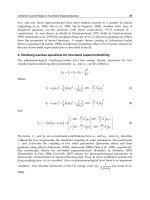
For rings with a square cross-section and radii large enough to neglect the magnetic pole
volume densities, the authors shew that the axial force exerted between the magnets as well
as the corresponding siffness was the same whatever the polarization direction, axial or radial.
For instance, this is illustrated for a radial bearing of following dimensions: r
in2
= 0.01 m,
r
out2
= 0.02 m, r
in
= 0.03 m, r
out
= 0.04 m, z
b
−z
a
= h = 0.1 m, J = 1 T.
Fig. 22 gives the results obtained for a bearing with radial polarization. These results are to
be compared with the ones of Fig. 23 corresponding to axial polarizations.
0.04 0.02 0 0.02 0.04
z m
30
20
10
0
10
20
30
Axial Force N
0.04 0.02 0 0.02 0.04
z m
6000
4000
2000
0
2000
Axial Stiffness Nm
Fig. 22. Axial force and stiffness versus axial displacement for two ring permanent magnets
with radial polarizations; r
1
= 0.01 m, r
2
= 0.02 m, r
3
= 0.03 m, r
4
= 0.04 m, z
2
− z
1
=
z
4
−z
3
= 0.1 m, J = 1 T
Passive permanent magnet bearings for rotating shaft : Analytical calculation 107
f (α, β, γ, h, z
a
, b, θ) =
−
γ log
α − γ cos(θ) +
α
2
+ γ
2
+ z
2
a
−2αγ cos(θ)
+ γ log
α − γ cos(θ) +
α
2
+ γ
2
+ (z
a
+ b)
2
−2αγ cos(θ)
+ γ log
α − γ cos(θ) +
α
2
+ γ
2
+ (z
a
− h)
2
−2αγ cos(θ)
−γ log
α − γ cos(θ) +
α
2
+ γ
2
+ (b − h)
2
+ 2z
a
(b −h) + z
2
a
−2αγ cos(θ)
+ γ log
β − γ cos(θ) +
β
2
+ γ
2
+ z
2
a
−2αγ cos(θ)
−γ log
β − γ cos(θ) +
β
2
+ γ
2
+ (z
a
+ b)
2
−2αγ cos(θ)
+ γ log
β − γ cos(θ) +
β
2
+ γ
2
+ (z
a
− h)
2
−2αγ cos(θ)
−γ log
β − γ cos(θ) +
β
2
+ γ
2
+ (b − h)
2
+ 2z
a
(b −h) + z
2
a
−2αγ cos(θ)
(45)
The third contribution K
V
is given by:
K
V
=
σ
∗
1
σ
∗
2
2µ
0
2π
θ
=0
r
out
r
1
=r
in
δdθ (46)
with
δ
= −log
r
in2
−r
1
cos(θ) +
r
2
1
+ r
2
in2
+ z
2
a
−2r
1
r
in2
cos(θ)
+ log
r
in2
−r
1
cos(θ) +
r
2
1
+ r
2
in2
+ (z
a
+ b)
2
−2r
1
r
in2
cos(θ)
−log
r
in2
−r
1
cos(θ) +
r
2
1
+ r
2
in2
+ (b − h)
2
+ 2bz
a
−2hz
a
+ z
2
a
−2r
1
r
in2
cos(θ)
+ log
r
in2
−r
1
cos(θ) +
r
2
1
+ r
2
in2
+ (z
a
− h)
2
−2r
1
r
in2
cos(θ)
+ log
r
out2
−r
1
cos(θ) +
r
2
1
+ r
2
out2
+ z
2
a
−2r
1
r
out2
cos(θ)
−log
r
out2
−r
1
cos(θ) +
r
2
1
+ r
2
out2
+ (z
a
+ b)
2
−2r
1
r
out2
cos(θ)
−log
r
out2
−r
1
cos(θ) +
r
2
1
+ r
2
out2
+ (z
a
− h)
2
−2r
1
r
out2
cos(θ)
+ log
r
out2
−r
1
cos(θ) +
r
2
1
+ r
2
out2
+ (b − h)
2
+ 2bz
a
−2hz
a
+ z
2
a
−2r
1
r
out2
cos(θ)
(47)
As a remark, the expression of the axial stiffness can be determined analytically if the magnetic
pole surface densities of each ring only are taken into account, so, if the magnetic pole volume
densities can be neglected. This is possible when the radii of the ring permanent magnets are
large enough (Ravaud, Lemarquand, Lemarquand & Depollier, 2009).
7. Study and characteristics of bearings with radially polariz ed ring magnets.
Radially polarized ring magnets can be used to realize passive bearings, either with a cylindri-
cal air gap or with a plane one. A device with a cylindrical air gap works as an axial bearing
when the ring magnets have the same radial polarization direction, whereas it works as a
radial one for opposite radial polarizations.
For rings with a square cross-section and radii large enough to neglect the magnetic pole
volume densities, the authors shew that the axial force exerted between the magnets as well
as the corresponding siffness was the same whatever the polarization direction, axial or radial.
For instance, this is illustrated for a radial bearing of following dimensions: r
in2
= 0.01 m,
r
out2
= 0.02 m, r
in
= 0.03 m, r
out
= 0.04 m, z
b
−z
a
= h = 0.1 m, J = 1 T.
Fig. 22 gives the results obtained for a bearing with radial polarization. These results are to
be compared with the ones of Fig. 23 corresponding to axial polarizations.
0.04 0.02 0 0.02 0.04
z m
30
20
10
0
10
20
30
Axial Force N
0.04 0.02 0 0.02 0.04
z m
6000
4000
2000
0
2000
Axial Stiffness Nm
Fig. 22. Axial force and stiffness versus axial displacement for two ring permanent magnets
with radial polarizations; r
1
= 0.01 m, r
2
= 0.02 m, r
3
= 0.03 m, r
4
= 0.04 m, z
2
− z
1
=
z
4
−z
3
= 0.1 m, J = 1 T
Magnetic Bearings, Theory and Applications108
0.04 0.02 0 0.02 0.04
z m
30
20
10
0
10
20
30
Axial Force N
0.04 0.02 0 0.02 0.04
z m
6000
4000
2000
0
2000
Axial Stiffness Nm
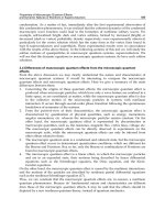
Fig. 23. Axial force and stiffness versus axial displacement for two ring permanent magnets
with axial polarizations; r
1
= 0.01 m, r
2
= 0.02 m, r
3
= 0.03 m, r
4
= 0.04 m, z
2
− z
1
=
z
4
−z
3
= 0.1 m, J = 1 T
These figures show clearly that the performances are the same. Indeed, for the radial polar-
izations the maximal axial force exerted by the outer ring on the inner one is 37.4 N and the
maximal axial stiffness is
|
K
z
|
=
7205 N/m and for the axial polarizations the maximal axial
force exerted by the outer ring on the inner one is 35.3 N and the maximal axial stiffness is
|
K
z
|
=
6854 N/m.
Moreover, the same kind of results is obtained when radially polarized ring magnets with
alternate polarizations are stacked: the performances are the same as for axially polarized
stacked rings.
So, as the radial polarization is far more difficult to realize than the axial one, these calcula-
tions show that it isn’t interesting from a practical point of view to use radially polarized ring
magnets to build bearings.
Nevertheless, this conclusion will be moderated by the next section. Indeed, the use of
“mixed” polarization directions in a device leads to very interesting results.
2
0
r
r
r
r
u
r
u
u
z
z
z
z
z
1
2
3
4
J
J
31
4
Fig. 24. Ring permanent magnets with perpendicular polarizations.
8. Determination of the force exerted between two ring permanent magnets with
perpendicular polarizations
The geometry considered is shown in Fig. 24: two concentric ring magnets separated by a
cylindrical air gap. The outer ring is radially polarized and the inner one is axially polarized,
hence the reference to “perpendicular” polarization.
8.1 Notations
The following parameters are used:
r
1
, r
2
: inner and outer radius of the inner ring permanent magnet [m]
r
3
, r
4
: inner and outer radius of the outer ring permanent magnet [m]
z
1
, z
2
: lower and upper axial abscissa of the inner ring permanent magnet [m]
z
3
, z
4
: inner and outer axial abscissa of the outer ring permanent magnet [m]
The two ring permanent magnets are radially centered and their polarization are supposed
uniformly radial.
8.2 Magnet modelling
The coulombian model is chosen for the magnets. So, each ring permanent magnet is repre-
sented by faces charged with fictitious magnetic pole surface densities. The outer ring perma-
nent magnet which is radially polarized is modelled as in the previous section. The outer face
is charged with the fictitious magnetic pole surface density
−σ
∗
and the inner one is charged
with the fictitious magnetic pole surface density
+σ
∗
. Both faces are cylindrical. Moreover,
the contribution of the magnetic pole volume density will be neglected for simplifying the
calculations.
The faces of the inner ring permanent magnet which is axially polarized are plane ones: the
upper face is charged with the fictitious magnetic pole surface density
−σ
∗
and the lower one
Passive permanent magnet bearings for rotating shaft : Analytical calculation 109
0.04 0.02 0 0.02 0.04
z m
30
20
10
0
10
20
30
Axial Force N
0.04 0.02 0 0.02 0.04
z m
6000
4000
2000
0
2000
Axial Stiffness Nm
Fig. 23. Axial force and stiffness versus axial displacement for two ring permanent magnets
with axial polarizations; r
1
= 0.01 m, r
2
= 0.02 m, r
3
= 0.03 m, r
4
= 0.04 m, z
2
− z
1
=
z
4
−z
3
= 0.1 m, J = 1 T
These figures show clearly that the performances are the same. Indeed, for the radial polar-
izations the maximal axial force exerted by the outer ring on the inner one is 37.4 N and the
maximal axial stiffness is
|
K
z
|
=
7205 N/m and for the axial polarizations the maximal axial
force exerted by the outer ring on the inner one is 35.3 N and the maximal axial stiffness is
|
K
z
|
=
6854 N/m.
Moreover, the same kind of results is obtained when radially polarized ring magnets with
alternate polarizations are stacked: the performances are the same as for axially polarized
stacked rings.
So, as the radial polarization is far more difficult to realize than the axial one, these calcula-
tions show that it isn’t interesting from a practical point of view to use radially polarized ring
magnets to build bearings.
Nevertheless, this conclusion will be moderated by the next section. Indeed, the use of
“mixed” polarization directions in a device leads to very interesting results.
2
0
r
r
r
r
u
r
u
u
z
z
z
z
z
1
2
3
4
J
J
31
4
Fig. 24. Ring permanent magnets with perpendicular polarizations.
8. Determination of the force exerted between two ring permanent magnets with
perpendicular polarizations
The geometry considered is shown in Fig. 24: two concentric ring magnets separated by a
cylindrical air gap. The outer ring is radially polarized and the inner one is axially polarized,
hence the reference to “perpendicular” polarization.
8.1 Notations
The following parameters are used:
r
1
, r
2
: inner and outer radius of the inner ring permanent magnet [m]
r
3
, r
4
: inner and outer radius of the outer ring permanent magnet [m]
z
1
, z
2
: lower and upper axial abscissa of the inner ring permanent magnet [m]
z
3
, z
4
: inner and outer axial abscissa of the outer ring permanent magnet [m]
The two ring permanent magnets are radially centered and their polarization are supposed
uniformly radial.
8.2 Magnet modelling
The coulombian model is chosen for the magnets. So, each ring permanent magnet is repre-
sented by faces charged with fictitious magnetic pole surface densities. The outer ring perma-
nent magnet which is radially polarized is modelled as in the previous section. The outer face
is charged with the fictitious magnetic pole surface density
−σ
∗
and the inner one is charged
with the fictitious magnetic pole surface density
+σ
∗
. Both faces are cylindrical. Moreover,
the contribution of the magnetic pole volume density will be neglected for simplifying the
calculations.
The faces of the inner ring permanent magnet which is axially polarized are plane ones: the
upper face is charged with the fictitious magnetic pole surface density
−σ
∗
and the lower one
Magnetic Bearings, Theory and Applications110
is charged with the fictitious magnetic pole surface density +σ
∗
. All the illustrative calcula-
tions are done with σ
∗
=
J.
n = 1 T, where
J is the magnetic polarization vector and
n is the
unit normal vector.
8.3 Force calculation
The axial force exerted between the two magnets with perpendicular polarizations can be
determined by:
F
z
=
J
2
4πµ
0
r
2
r
1
2π
0
H
z
(r, z
3
)rdrdθ
−
J
2
4πµ
0
r
2
r
1
2π
0
H
z
(r, z
4
)rdrdθ
(46)
where H
z
(r, z) is the axial magnetic field produced by the outer ring permanent magnet. This
axial field can be expressed as follows:
H
z
(r, z) =
J
4πµ
0
S
(z −
˜
z
)
R(r
3
,
˜
θ,
˜
z)
r
3
d
˜
θd
˜
z
−
J
4πµ
0
S
(z −
˜
z
)
R(r
4
,
˜
θ,
˜
z)
r
4
d
˜
θd
˜
z
(45)
with
R
(r
i
,
˜
θ,
˜
z) =
r
2
+ r
2
i
−2r r
i
cos(
˜
θ
) + (z −
˜
z
)
2
3
2
(45)
The expression of the force can be reduced to:
F
z
=
J
2
4πµ
0
2
∑
i,k=1
4
∑
j,l=3
(−1)
i+j+k+l
A
i,j,k,l
+
J
2
4πµ
0
2
∑
i,k=1
4
∑
j,l=3
(−1)
i+j+k+l
S
i,j,k,l
(44)
with
A
i,j,k,l
= −8πr
i
E
−
4r
i
r
j
S
i,j,k,l
= −2πr
2
j
2π
0
cos(θ) ln
[
β + α
]
dθ
(43)
where E
[
m
]
gives the complete elliptic integral which is expressed as follows:
E
[
m
]
=
π
2
0
1 −m sin(θ)
2
dθ (43)
The parameters , α and β depend on the ring permanent magnet dimensions and are defined
by:
= (r
i
−r
j
)
2
+ (z
k
−z
l
)
2
α =
r
2
i
+ r
2
j
−2r
i
r
j
cos(θ) + (z
k
−z
l
)
2
β = r
i
−r
j
cos(θ)
(41)
8.4 Stiffness exerted between two ring permanent magnets with perpendicular polarizations
The axial stiffness derives from the axial force:
K
z
= −
d
dz
F
z
(41)
where F
z
is determined with R(r
i
,
˜
θ,
˜
z) and Eq. (46). After mathematical manipulations, the
previous expression can be reduced in the following form:
K
z
=
J
2
4πµ
0
2
∑
i,k=1
4
∑
j,l=3
(−1)
i+j+k+l
k
i,j,k,l
(41)
with
k
i,j,k,l
= −
2π
0
r
j
(z
k
−z
l
)(α + r
i
)
α
(
α + β
)
dθ
(41)
9. Study and characteristics of bearings using ring magnets with perpendicular
polarizations.
9.1 Structures with two ring magnets
The axial force and stiffness are calculated for the bearing constituted by an outer radially
polarized ring magnet and an inner axially polarized one. The device dimensions are the
same as in section 7. Thus, the results obtained for this bearing and shown in Fig. 25 are
easily compared to the previous ones: the maximal axial force is 39.7 N and the maximal axial
stiffness is
|
K
z
|
=
4925 N/m.
So, the previous calculations show that the greatest axial force is obtained in the bearing using
ring permanent magnets with perpendicular polarizations whereas the greatest axial stiffness
is obtained in the one using ring permanent magnets with radial polarizations.
9.2 Multiple ring structures: stacks forming Halbach patterns
The conclusion of the preceding section naturally leads to mixed structures which would have
both advantages of a great force and a great stiffness. This is achieved with bearings consti-
tuted of stacked ring magnets forming a Halbach pattern (Halbach, 1980).
Passive permanent magnet bearings for rotating shaft : Analytical calculation 111
is charged with the fictitious magnetic pole surface density +σ
∗
. All the illustrative calcula-
tions are done with σ
∗
=
J.
n = 1 T, where
J is the magnetic polarization vector and
n is the
unit normal vector.
8.3 Force calculation
The axial force exerted between the two magnets with perpendicular polarizations can be
determined by:
F
z
=
J
2
4πµ
0
r
2
r
1
2π
0
H
z
(r, z
3
)rdrdθ
−
J
2
4πµ
0
r
2
r
1
2π
0
H
z
(r, z
4
)rdrdθ
(46)
where H
z
(r, z) is the axial magnetic field produced by the outer ring permanent magnet. This
axial field can be expressed as follows:
H
z
(r, z) =
J
4πµ
0
S
(z −
˜
z
)
R(r
3
,
˜
θ,
˜
z)
r
3
d
˜
θd
˜
z
−
J
4πµ
0
S
(z −
˜
z
)
R(r
4
,
˜
θ,
˜
z)
r
4
d
˜
θd
˜
z
(45)
with
R
(r
i
,
˜
θ,
˜
z) =
r
2
+ r
2
i
−2r r
i
cos(
˜
θ
) + (z −
˜
z
)
2
3
2
(45)
The expression of the force can be reduced to:
F
z
=
J
2
4πµ
0
2
∑
i,k=1
4
∑
j,l=3
(−1)
i+j+k+l
A
i,j,k,l
+
J
2
4πµ
0
2
∑
i,k=1
4
∑
j,l=3
(−1)
i+j+k+l
S
i,j,k,l
(44)
with
A
i,j,k,l
= −8πr
i
E
−
4r
i
r
j
S
i,j,k,l
= −2πr
2
j
2π
0
cos(θ) ln
[
β + α
]
dθ
(43)
where E
[
m
]
gives the complete elliptic integral which is expressed as follows:
E
[
m
]
=
π
2
0
1
−m sin(θ)
2
dθ (43)
The parameters , α and β depend on the ring permanent magnet dimensions and are defined
by:
= (r
i
−r
j
)
2
+ (z
k
−z
l
)
2
α =
r
2
i
+ r
2
j
−2r
i
r
j
cos(θ) + (z
k
−z
l
)
2
β = r
i
−r
j
cos(θ)
(41)
8.4 Stiffness exerted between two ring permanent magnets with perpendicular polarizations
The axial stiffness derives from the axial force:
K
z
= −
d
dz
F
z
(41)
where F
z
is determined with R(r
i
,
˜
θ,
˜
z) and Eq. (46). After mathematical manipulations, the
previous expression can be reduced in the following form:
K
z
=
J
2
4πµ
0
2
∑
i,k=1
4
∑
j,l=3
(−1)
i+j+k+l
k
i,j,k,l
(41)
with
k
i,j,k,l
= −
2π
0
r
j
(z
k
−z
l
)(α + r
i
)
α
(
α + β
)
dθ
(41)
9. Study and characteristics of bearings using ring magnets with perpendicular
polarizations.
9.1 Structures with two ring magnets
The axial force and stiffness are calculated for the bearing constituted by an outer radially
polarized ring magnet and an inner axially polarized one. The device dimensions are the
same as in section 7. Thus, the results obtained for this bearing and shown in Fig. 25 are
easily compared to the previous ones: the maximal axial force is 39.7 N and the maximal axial
stiffness is
|
K
z
|
=
4925 N/m.
So, the previous calculations show that the greatest axial force is obtained in the bearing using
ring permanent magnets with perpendicular polarizations whereas the greatest axial stiffness
is obtained in the one using ring permanent magnets with radial polarizations.
9.2 Multiple ring structures: stacks forming Halbach patterns
The conclusion of the preceding section naturally leads to mixed structures which would have
both advantages of a great force and a great stiffness. This is achieved with bearings consti-
tuted of stacked ring magnets forming a Halbach pattern (Halbach, 1980).
Magnetic Bearings, Theory and Applications112
0.04 0.02 0 0.02 0.04
z m
40
30
20
10
0
10
Axial Force N
0.04 0.02 0 0.02 0.04
z m
4000
2000
0
2000
4000
Axial Stiffness Nm
Fig. 25. Axial force axial stiffness versus axial displacement for two ring permanent magnets
with perpendicular polarizations; r
1
= 0.01 m, r
2
= 0.02 m, r
3
= 0.03 m, r
4
= 0.04 m,
z
2
−z
1
= z
4
−z
3
= 0.1 m, J = 1 T
Fig. 26. Cross-section of a stack of five ring permanent magnets with perpendicular polar-
izations; r
1
= 0.01 m, r
2
= 0.02 m, r
3
= 0.03 m, r
4
= 0.04 m, J = 1 T, height of each ring
permanent magnet = 0.01 m
0.04 0.02 0 0.02 0.04
z m
400
200
0
200
400
Axial Force N
0.04 0.02 0 0.02 0.04
z m
80000
60000
40000
20000
0
20000
40000
60000
Axial Stiffness Nm
Fig. 27. Axial force and stiffness versus axial displacement for a stack of five ring permanent
magnets with perpendicular polarizations; r
1
= 0.01 m, r
2
= 0.02 m, r
3
= 0.03 m, r
4
= 0.04 m,
J
= 1 T, height of each ring permanent magnet = 0.01 m
Section 4.2 shew that stacking ring magnets with alternate polarization led to structures with
higher performances than the ones with two magnets for a given magnet volume. So, the per-
formances will be compared for stacked structures, either with alternate radial polarizations
or with perpendicular ones.
Thus, the bearing considered is constituted of five ring magnets with polarizations alternately
radial and axial (Fig. 26). The axial force and stiffness are calculated with the previously
presented formulations (Fig.27).
The same calculations are carried out for a stack of five rings with radial alternate polarizations
having the same dimensions (Fig. 28). It is to be noted that the result would be the same for a
stack of five rings with axial alternate polarizations of same dimensions.
As a result, the maximal axial force exerted in the case of alternate magnetizations is 122 N
whereas it reaches 503 N with a Halbach configuration. Moreover, the maximal axial stiffness
is
|
K
z
|
=
34505 N/m for alternate polarizations and
|
K
z
|
=
81242 N/m for the perpendicular
ones. Thus, the force is increased fourfold and the stiffness twofold in the Halbah structure
when compared to the alternate one. Consequently, bearings constituted of stacked rings with
perpendicular polarizations are far more efficient than those with alternate polarizations. This
shows that for a given magnet volume these Halbach pattern structures are the ones that give
the greatest axial force and stiffness. So, this can be a good reason to use radially polarized
ring magnets in passive magnetic bearings.
10. Conclusion
This chapter presents structures of passive permanent magnet bearings. From the simplest
bearing with two axially polarized ring magnets to the more complicated one with stacked
rings having perpendicular polarizations, the structures are described and studied. Indeed,
Passive permanent magnet bearings for rotating shaft : Analytical calculation 113
0.04 0.02 0 0.02 0.04
z m
40
30
20
10
0
10
Axial Force N
0.04 0.02 0 0.02 0.04
z m
4000
2000
0
2000
4000
Axial Stiffness Nm
Fig. 25. Axial force axial stiffness versus axial displacement for two ring permanent magnets
with perpendicular polarizations; r
1
= 0.01 m, r
2
= 0.02 m, r
3
= 0.03 m, r
4
= 0.04 m,
z
2
−z
1
= z
4
−z
3
= 0.1 m, J = 1 T
Fig. 26. Cross-section of a stack of five ring permanent magnets with perpendicular polar-
izations; r
1
= 0.01 m, r
2
= 0.02 m, r
3
= 0.03 m, r
4
= 0.04 m, J = 1 T, height of each ring
permanent magnet = 0.01 m
0.04 0.02 0 0.02 0.04
z m
400
200
0
200
400
Axial Force N
0.04 0.02 0 0.02 0.04
z m
80000
60000
40000
20000
0
20000
40000
60000
Axial Stiffness Nm
Fig. 27. Axial force and stiffness versus axial displacement for a stack of five ring permanent
magnets with perpendicular polarizations; r
1
= 0.01 m, r
2
= 0.02 m, r
3
= 0.03 m, r
4
= 0.04 m,
J
= 1 T, height of each ring permanent magnet = 0.01 m
Section 4.2 shew that stacking ring magnets with alternate polarization led to structures with
higher performances than the ones with two magnets for a given magnet volume. So, the per-
formances will be compared for stacked structures, either with alternate radial polarizations
or with perpendicular ones.
Thus, the bearing considered is constituted of five ring magnets with polarizations alternately
radial and axial (Fig. 26). The axial force and stiffness are calculated with the previously
presented formulations (Fig.27).
The same calculations are carried out for a stack of five rings with radial alternate polarizations
having the same dimensions (Fig. 28). It is to be noted that the result would be the same for a
stack of five rings with axial alternate polarizations of same dimensions.
As a result, the maximal axial force exerted in the case of alternate magnetizations is 122 N
whereas it reaches 503 N with a Halbach configuration. Moreover, the maximal axial stiffness
is
|
K
z
|
=
34505 N/m for alternate polarizations and
|
K
z
|
=
81242 N/m for the perpendicular
ones. Thus, the force is increased fourfold and the stiffness twofold in the Halbah structure
when compared to the alternate one. Consequently, bearings constituted of stacked rings with
perpendicular polarizations are far more efficient than those with alternate polarizations. This
shows that for a given magnet volume these Halbach pattern structures are the ones that give
the greatest axial force and stiffness. So, this can be a good reason to use radially polarized
ring magnets in passive magnetic bearings.
10. Conclusion
This chapter presents structures of passive permanent magnet bearings. From the simplest
bearing with two axially polarized ring magnets to the more complicated one with stacked
rings having perpendicular polarizations, the structures are described and studied. Indeed,
Magnetic Bearings, Theory and Applications114
0.04 0.02 0 0.02 0.04
z m
100
50
0
50
100
Axial Force N
0.04 0.02 0 0.02 0.04
z m
30000
20000
10000
0
10000
20000
Axial Stiffness Nm
Fig. 28. Axial force and stiffness versus axial displacement for a stack of five ring permanent
magnets with radial polarizations; r
1
= 0.01 m, r
2
= 0.02 m, r
3
= 0.03 m, r
4
= 0.04 m, J = 1 T,
height of each ring permanent magnet = 0.01 m
analytical formulations for the axial force and stiffness are given for each case of axial, ra-
dial or perpendicular polarization. Moreover, it is to be noted that Mathematica Files con-
taining the expressions presented in this paper are freely available online (v-
lemans.fr/
∼glemar, n.d.). These expressions allow the quantitative study and the comparison
of the devices, as well as their optimization and have a very low computational cost. So, the
calculations show that a stacked structure of “small” magnets is more efficient than a structure
with two “large” magnets, for a given magnet volume. Moreover, the use of radially polar-
ized magnets, which are difficult to realize, doesn’t lead to real advantages unless it is done
in association with axially polarized magnets to build Halbach pattern. In this last case, the
bearing obtained has the best performances of all the structures for a given magnet volume.
Eventually, the final choice will depend on the intended performances, dimensions and cost
and the expressions of the force and stiffness are useful tools to help the choice.
11. References
Azukizawa, T., Yamamoto, S. & Matsuo, N. (2008). Feasibility study of a passive magnetic
bearing using the ring shaped permanent magnets, IEEE Trans. Magn. 44(11): 4277–
4280.
Azzerboni, B. & Cardelli, E. (1993). Magnetic field evaluation for disk conductors, IEEE Trans.
Magn. 29(6): 2419–2421.
Babic, S. I. & Akyel, C. (2008a). Improvement in the analytical calculation of the magnetic field
produced by permanent magnet rings, Prog. Electromagn. Res. C 5: 71–82.
Babic, S. I. & Akyel, C. (2008b). Magnetic force calculation between thin coaxial circular coils
in air, IEEE Trans. Magn. 44(4): 445–452.
Barthod, C. & Lemarquand, G. (1995). Degrees of freedom control of a magnetically levitated
rotor, IEEE Trans. Magn. 31(6): 4202–4204.
Durand, E. (1968). Magnetostatique, Masson Editeur, Paris, France.
Filatov, A. & Maslen, E. (2001). Passive magnetic bearing for flywheel energy storage systems,
IEEE Trans. Magn. 37(6): 3913–3924.
Halbach, K. (1980). Design of permanent multiple magnets with oriented rec material, Nucl.
Inst. Meth. 169: 1–10.
Hijikata, K., Takemoto, M., Ogasawara, S., Chiba, A. & Fukao, T. (2009). Behavior of a novel
thrust magnetic bearing with a cylindrical rotor on high speed rotation, IEEE Trans.
Magn. 45(10): 4617–4620.
Holmes, F. T. & Beams, J. W. (1937). Frictionnal torque of an axial magnetic suspension, Nature
140: 30–31.
/>∼glemar (n.d.).
Hussien, A. A., Yamada, S., Iwahara, M., Okada, T. & Ohji, T. (2005). Application of the
repulsive-type magnetic bearing for manufacturing micromass measurement balance
equipment, IEEE Trans. Magn. 41(10): 3802–3804.
Janssen, J., Paulides, J., Compter, J. & Lomonova, E. (2010). Threee-dimensional analytical
calculation of the torque between permanent magnets in magnetic bearings, IEEE
Trans. Mag. 46(6): 1748–1751.
Kim, K., Levi, E., Zabar, Z. & Birenbaum, L. (1997). Mutual inductance of noncoaxial circular
coils with constant current density, IEEE Trans. Magn. 33(5): 4303–4309.
Lang, M. (2002). Fast calculation method for the forces and stiffnesses of permanent-magnet
bearings, 8th International Symposium on Magnetic Bearing pp. 533–537.
Lemarquand, G. & Yonnet, J. (1998). A partially passive magnetic suspension for a discoidal
wheel., J. Appl. Phys. 64(10): 5997–5999.
Meeks, C. (1974). Magnetic bearings, optimum design and applications, First workshop on
RE-Co permanent magnets, Dayton.
Mukhopadhyay, S. C., Donaldson, J., Sengupta, G., Yamada, S., Chakraborty, C. & Kacprzak,
D. (2003). Fabrication of a repulsive-type magnetic bearing using a novel ar-
rangement of permanent magnets for vertical-rotor suspension, IEEE Trans. Magn.
39(5): 3220–3222.
Ravaud, R., Lemarquand, G. & Lemarquand, V. (2009a). Force and stiffness of passive mag-
netic bearings using permanent magnets. part 1: axial magnetization, IEEE Trans.
Magn. 45(7): 2996–3002.
Passive permanent magnet bearings for rotating shaft : Analytical calculation 115
0.04 0.02 0 0.02 0.04
z m
100
50
0
50
100
Axial Force N
0.04 0.02 0 0.02 0.04
z m
30000
20000
10000
0
10000
20000
Axial Stiffness Nm
Fig. 28. Axial force and stiffness versus axial displacement for a stack of five ring permanent
magnets with radial polarizations; r
1
= 0.01 m, r
2
= 0.02 m, r
3
= 0.03 m, r
4
= 0.04 m, J = 1 T,
height of each ring permanent magnet = 0.01 m
analytical formulations for the axial force and stiffness are given for each case of axial, ra-
dial or perpendicular polarization. Moreover, it is to be noted that Mathematica Files con-
taining the expressions presented in this paper are freely available online (v-
lemans.fr/
∼glemar, n.d.). These expressions allow the quantitative study and the comparison
of the devices, as well as their optimization and have a very low computational cost. So, the
calculations show that a stacked structure of “small” magnets is more efficient than a structure
with two “large” magnets, for a given magnet volume. Moreover, the use of radially polar-
ized magnets, which are difficult to realize, doesn’t lead to real advantages unless it is done
in association with axially polarized magnets to build Halbach pattern. In this last case, the
bearing obtained has the best performances of all the structures for a given magnet volume.
Eventually, the final choice will depend on the intended performances, dimensions and cost
and the expressions of the force and stiffness are useful tools to help the choice.
11. References
Azukizawa, T., Yamamoto, S. & Matsuo, N. (2008). Feasibility study of a passive magnetic
bearing using the ring shaped permanent magnets, IEEE Trans. Magn. 44(11): 4277–
4280.
Azzerboni, B. & Cardelli, E. (1993). Magnetic field evaluation for disk conductors, IEEE Trans.
Magn. 29(6): 2419–2421.
Babic, S. I. & Akyel, C. (2008a). Improvement in the analytical calculation of the magnetic field
produced by permanent magnet rings, Prog. Electromagn. Res. C 5: 71–82.
Babic, S. I. & Akyel, C. (2008b). Magnetic force calculation between thin coaxial circular coils
in air, IEEE Trans. Magn. 44(4): 445–452.
Barthod, C. & Lemarquand, G. (1995). Degrees of freedom control of a magnetically levitated
rotor, IEEE Trans. Magn. 31(6): 4202–4204.
Durand, E. (1968). Magnetostatique, Masson Editeur, Paris, France.
Filatov, A. & Maslen, E. (2001). Passive magnetic bearing for flywheel energy storage systems,
IEEE Trans. Magn. 37(6): 3913–3924.
Halbach, K. (1980). Design of permanent multiple magnets with oriented rec material, Nucl.
Inst. Meth. 169: 1–10.
Hijikata, K., Takemoto, M., Ogasawara, S., Chiba, A. & Fukao, T. (2009). Behavior of a novel
thrust magnetic bearing with a cylindrical rotor on high speed rotation, IEEE Trans.
Magn. 45(10): 4617–4620.
Holmes, F. T. & Beams, J. W. (1937). Frictionnal torque of an axial magnetic suspension, Nature
140: 30–31.
/>∼glemar (n.d.).
Hussien, A. A., Yamada, S., Iwahara, M., Okada, T. & Ohji, T. (2005). Application of the
repulsive-type magnetic bearing for manufacturing micromass measurement balance
equipment, IEEE Trans. Magn. 41(10): 3802–3804.
Janssen, J., Paulides, J., Compter, J. & Lomonova, E. (2010). Threee-dimensional analytical
calculation of the torque between permanent magnets in magnetic bearings, IEEE
Trans. Mag. 46(6): 1748–1751.
Kim, K., Levi, E., Zabar, Z. & Birenbaum, L. (1997). Mutual inductance of noncoaxial circular
coils with constant current density, IEEE Trans. Magn. 33(5): 4303–4309.
Lang, M. (2002). Fast calculation method for the forces and stiffnesses of permanent-magnet
bearings, 8th International Symposium on Magnetic Bearing pp. 533–537.
Lemarquand, G. & Yonnet, J. (1998). A partially passive magnetic suspension for a discoidal
wheel., J. Appl. Phys. 64(10): 5997–5999.
Meeks, C. (1974). Magnetic bearings, optimum design and applications, First workshop on
RE-Co permanent magnets, Dayton.
Mukhopadhyay, S. C., Donaldson, J., Sengupta, G., Yamada, S., Chakraborty, C. & Kacprzak,
D. (2003). Fabrication of a repulsive-type magnetic bearing using a novel ar-
rangement of permanent magnets for vertical-rotor suspension, IEEE Trans. Magn.
39(5): 3220–3222.
Ravaud, R., Lemarquand, G. & Lemarquand, V. (2009a). Force and stiffness of passive mag-
netic bearings using permanent magnets. part 1: axial magnetization, IEEE Trans.
Magn. 45(7): 2996–3002.
Magnetic Bearings, Theory and Applications116
Ravaud, R., Lemarquand, G. & Lemarquand, V. (2009b). Force and stiffness of passive mag-
netic bearings using permanent magnets. part 2: radial magnetization, IEEE Trans.
Magn. 45(9): 3334–3342.
Ravaud, R., Lemarquand, G., Lemarquand, V. & Depollier, C. (2008). Analytical calculation of
the magnetic field created by permanent-magnet rings, IEEE Trans. Magn. 44(8): 1982–
1989.
Ravaud, R., Lemarquand, G., Lemarquand, V. & Depollier, C. (2009). Discussion about the an-
alytical calculation of the magnetic field created by permanent magnets., Prog. Elec-
tromagn. Res. B 11: 281–297.
Samanta, P. & Hirani, H. (2008). Magnetic bearing configurations: Theoretical and experimen-
tal studies, IEEE Trans. Magn. 44(2): 292–300.
Yonnet, J. P. (1978). Passive magnetic bearings with permanent magnets, IEEE Trans. Magn.
14(5): 803–805.
Yonnet, J. P., Lemarquand, G., Hemmerlin, S. & Rulliere, E. (1991). Stacked structures of
passive magnetic bearings, J. Appl. Phys. 70(10): 6633–6635.
A rotor model with two gradient static eld shafts and a bulk twined heads system 117
A rotor model with two gradient static eld shafts and a bulk twined heads
system
Hitoshi Ozaku
X
A rotor model with
two gradient static field shafts
and a bulk twined heads system
Hitoshi Ozaku
Railway Technical Research Institute
Japan
1. Introduction
The noncontact high speed rotor is one of dream for many engineers. There are many
investigations. At example, one is the bearing less motor, another is flywheel using the bulk
high temperature superconducting (HTS). The bearing less motor is needed the high
technical knowledge and the accurate system. HTS materials are effectively utilized to the
flywheel which needs the grater levitation force, to the motor of the ship which needs the
grater torque, and to the motor for the airplane which needs the grater torque and smaller
weight. It is very difficult that the rotor of the micro size type generator generates a high
power which rotating in a high speed.
Fig. 1. View of the original rotor model in 2007
As my first try in 2006, a small generator in which only one HTS bulk (47mm in diameter)
was arranged was tested for the levitation force, but it was useless as the synchronous
generator because of being unstable. And an axial gap type rotor improved to a new rotor
with two gradient static field shafts which is lifted between a set of the magnets and a
trapped static magnetic field of a HTS bulk. Furthermore, the improved rotor was so
6
Magnetic Bearings, Theory and Applications118
rearranged as to form a twin type combination of two bulks and two set of magnets
components (Figure 1). The concept of magnetic shafts which plays a role of the twined the
magnetic bearing was presented, and acts as magnetic spring.
For achieve the system which achieve the more convenient and continuously examinations
without use of liquid nitrogen, we fabricated bulk twined heads type pulse tube cryocooler
based on the above experimental.
And, I reported [1] that this system recorded at 2,000 rpm. Later, the improved system and
rotor recorded at 15,000 rpm.
2. System
2.1 Rotor model with two gradient static field shafts
The rotor is 70mm in diameter, 70mm in height, and consists of many size acrylic pipes of
various sizes. A set of the combined magnets consist of both a cylindrical magnet, 20mm in
diameter, 10mm in thickness, and 0.45T, and the two ring magnets, 30mm in inside
diameter, 50mm in outside diameter, 5mm in thickness, and 0.33T. The cylindrical magnet
was arranged to be the opposite pole in the centre of a ring magnet. The dissembled
drawing of the rotor is shown in figure 2. The detail of the structure of the rotor is shown in
figure 3. The centre ring part of the rotor is rotary mechanism part, and it can change easily
another differ type ring.
The magnetic distribution of a set of the magnets of the rotor measured by the Hall
generator with gap 0.5mm is shown in figure 4. In advance the trapped field distribution of
the supplied HTS bulk was measured with Hall generator at 0.5mm above the surface of the
bulk at over 1.5T field cooling. The peak value was at 0.9T. The relationship of the
distributions between the magnetic distribution of the rotor and the magnetic distribution of
a HTS bulk trapped in field cooling using liquid nitrogen by the permanent magnets of the
rotor is shown in figure 5. The shown values of the magnetic flux density of a HTS bulk in
figure 5 were reverse pole. The magnetic distributions of the both poles of the magnets of
the rotary mechanism part (8 poles, acrylic ring, in figure 3 and 9) of the rotor were shown
in figure 6. The x-axis is shown at vertical direction, and 0 point in x-axis is shown the hole
position the acrylic ring of the rotary mechanism part of the rotor.
Fig. 2. View of the rotor model
Fig. 3. Detail of component of the rotor model
Fig. 4. Magnetic distribution of a set the component of the permanent magnets of the rotor
Fig. 5. Magnetic flux density of a set the component of the permanent magnets of the rotor
and a trapped HTS bulk