Mass Transfer in Multiphase Systems and its Applications Part 4 pot
Bạn đang xem bản rút gọn của tài liệu. Xem và tải ngay bản đầy đủ của tài liệu tại đây (682.53 KB, 40 trang )
Mass Transfer in Multiphase Mechanically Agitated Systems
109
The effect of upper agitator type on the volumetric mass transfer coefficient value in the
gas–solid–liquid system is presented in Fig. 14.
0
2
4
6
8
10
123456
k
L
a
x 10
2
, 1/s
RT- A 315
RT- HE 3
X = 0.5 mass % X = 2.5 mass%
1.71
3.41
6.82
1.71
6.82
0
2
4
6
8
10
123456
k
L
a
x 10
2
, 1/s
RT- A 315
RT- HE 3
X = 0.5 mass % X = 2.5 mass%
1.71
3.41
6.82
1.71
6.82
0
2
4
6
8
10
123456
k
L
a
x 10
2
, 1/s
RT- A 315
RT- HE 3
X = 0.5 mass % X = 2.5 mass%
1.71
3.41
6.82
1.71
6.82
3.41
Fig. 14. Comparison of values of k
L
a coefficient for two impeller configurations, working in
gas–solid–liquid systems; X ≠ const; n = 15 1/s; various values of superficial gas velocity w
og
×10
-3
m/s
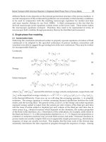
In the three–phase system that, which agitator ensure better conditions to conduct the
process of gas ingredient transfer between gas and liquid phase, depends significantly on
the quantity of gas introduced into the vessel. Comparison of values of k
L
a coefficient for
two impeller configurations, working in gas–solid–liquid systems with two different solid
concentrations is presented in Fig. 14. At lower value of superficial gas velocity (w
og
= 1.71
×10
-3
m/s) both in the system with lower solid particles concentration X = 0.5 mass % and
with greater one: X = 2.5 mass %, higher of about 20 % values of volumetric mass transfer
coefficient were obtained in the system agitated by means of the configuration with HE 3
impeller. With the increase of gas velocity w
og
the differences in the values of k
L
a coefficient
achieved for two tested impellers configuration significantly decreased. Moreover, in the
system with lower solid concentration at the velocity w
og
= 3.41×10
-3
m/s, in the whole
range of impeller speeds, k
L
a values for both sets of impellers were equal.
Completely different results were obtained when much higher quantity of gas phase were
introduced in the vessel. For high value of w
og
for both system including 0.5 and 2.5 mass %
of solid particles, more favourable was configuration Rushton turbine – A 315. Using this set
of agitators about 20 % higher values of the volumetric mass transfer coefficient were
obtained, comparing with the data characterized the vessel with HE 3 impeller as an upper
one (Fig. 12).
The data obtained for three–phase systems were also described mathematically. On the
strength of 150 experimental points Equation (2) was formulated:
G-L-S
L
2
L
12
1
1
b
c
og
P
ka A w
V
mX mX
⎛⎞
⎛⎞
=
⎜⎟
⎜⎟
⎜⎟
++
⎝⎠
⎝⎠
(6)
Mass Transfer in Multiphase Systems and its Applications
110
The values of the coefficient A, m
1
, m
2
, and exponents B, C in this Eq. are collected in Table 6
for single impeller system and in Table 7 for the configurations of double impeller differ in a
lower one. In these tables mean relative error ±Δ is also presented. For the vessel equipped
with single impeller Eq. (6) is applicable within following range of the measurements: P
G-L-
S
/V
L
∈ <118; 5700 W/m
3
>; w
og
∈ <1.71×10
-3
; 8.53×10
-3
m/s>; X ∈ <0.5; 5 mass %>. The range
of an application of this equation for the double impeller systems is as follows: P
G-L-S
/V
L
∈
<540; 5960 W/m
3
>; w
og
∈ <1.71×10
-3
; 6.82×10
-3
m/s>; X ∈ <0.5; 5 mass %>.
No. Impeller
A b c m
1
m
2
±Δ, %
Exp.
point
1. Rushton turbine (RT) 0.031 0.43 0.515 -186,67 11.921 6.8 100
2. Smith turbine (CD 6) 0.038 0.563 0.67 -388.62 23.469 6.6 98
3. A 315 0.062 0.522 0.774 209.86 -11.038 10.3 108
Table 6. The values of the coefficient A, m
1
, m
2
and exponents b, c in Eq. (6) for single
impeller systems (Kiełbus-Rąpała et al., 2010)
Configuration of impellers
No.
lower upper
A b c m
1
m
2
±Δ, %
1. CD 6 RT 0.164 0.318 0.665 0.361 8.81 3
2. A 315 RT 0.031 0.423 0.510 -0.526 -8.31 4
Table 7. The values of the coefficient A, m
1
, m
2
and exponents b, c
in Eq. (6) for double
impeller systems (Kiełbus-Rąpała & Karcz, 2009)
The results of the k
L
a coefficient measurements for the vessel equipped with double impeller
configurations differ in an upper impeller were described by Eq. 7.
1
1
B
C
GLS
Log
L
P
ka A w
VmX
−−
⎛⎞
=
⎜⎟
+
⎝⎠
(7)
The values of the coefficient A, m, and exponents B, C in this Eq. for both impeller designs
are collected in Table 8. The range of application of Eq. 2 is as follows: Re ∈ <9.7; 16.8×10
4
>;
P
G-L-S
/V
L
∈ <1100; 4950 W/m
3
>; w
og
∈ <1.71×10
-3
; 6.82×10
-3
m/s>; X ∈ <0; 0.025>.
Configuration of impellers
No.
lower upper
A B C m
±Δ, %
1. Rushton Turbine A 315 0.103 0.409 0.695 4.10 4.8
2. Rushton Turbine HE 3 0.031 0.423 0.510 6.17 6.4
Table 8. The values of the coefficient A and exponents B, C in Eq. (7) (Kiełbus-Rąpała &
Karcz 2010)
Mass Transfer in Multiphase Mechanically Agitated Systems
111
4. Conclusions
In the multi – phase systems the k
L
a coefficient value is affected by many factors, such as
geometrical parameters of the vessel, type of the impeller, operating parameters in which
process is conducted (impeller speed, aeration rate), properties of liquid phase (density,
viscosity, surface tension etc.) and additionally by the type, size and loading (%) of the solid
particles.
The results of the experimental analyze of the multiphase systems agitated by single
impeller and different configuration of two impellers on the common shaft show that within
the range of the performed measurements:
1. Single radial flow turbines enable to obtain better results compared to mixed flow A 315
impeller.
2. Geometry of lower as well as upper impeller has strong influence on the volumetric
mass transfer coefficient values. From the configurations used in the study for gas-
liquid system higher values of k
L
a characterized Smith turbine (lower)–Rushton turbine
and Rushton turbine–A 315 (upper) configurations.
3. In the vessel equipped with both single and double impellers the presence of the solids
in the gas–liquid system significantly affects the volumetric mass transfer coefficient
k
L
a. Within the range of the low values of the superficial gas velocity w
og
, high agitator
speeds n and low mean concentration X of the solids in the liquid, the value of the
coefficient k
L
a increases even about 20 % (for single impeller) comparing to the data
obtained for gas–liquid system. However, this trend decreases with the increase of both
w
og
and X values. For example, the increase of the k
L
a coefficient is equal to only 10 %
for the superficial gas velocity w
og
= 5.12 x10
-3
m/s. Moreover, within the highest range
of the agitator speeds n value of the k
L
a is even lower than that obtained for gas–liquid
system agitated by means of a single impeller.
In the case of using to agitation two impellers on the common shaft k
L
a coefficient
values were lower compared to a gas–liquid system at all superficial gas velocity
values.
4. The volumetric mass transfer coefficient increases, compared to the system without
solids, only below a certain level of particles concentration. Introducing more particles,
X = 2.5 mass % into the system causes a decrease of k
L
a in the system agitated by both
single and double impeller systems.
5. In the gas–solid–liquid system the choice of the configuration (upper impeller) strongly
depends on the gas phase participation in the liquid volume:
-The highest values of volumetric mass transfer coefficient in the system with small
value of gas phase init were obtained in the vessel with HE 3 upper stirrer;
-In the three-phase system, at large values of superficial gas velocity better
conditions to mass transfer process performance enable RT–A 315 configuration.
Symbols
a length of the blade m
B width of the baffle m
b width of the blade m
C concentration g/dm
3
D inner diameter of the agitated vessel m
d impeller diameter m
Mass Transfer in Multiphase Systems and its Applications
112
d
d
diameter of the gas sparger m
d
p
particles diameter m
e distance between gas sparger and bottom of the vessel m
H liquid height in the agitated vessel m
h
1
off – bottom clearance of lower agitator m
h
2
off – bottom clearance of upper agitator m
i number of the agitators
J number of baffles
k
L
a volumetric mass transfer coefficient s
-1
n agitator speed s
-1
n
JSG
critical impeller speed for gas – solid – liquid system s
-1
P power consumption W
R curvature radius of the blade m
t time s
V
L
liquid volume m
3
V
g
gas flow rate m
3
s
-1
w
og
superficial gas velocity (= 4 V
g
/πD
2
)· m s
-1
X mass fraction of the particles % w/w
Z number of blades
Greek Letters
β
pitch of the impeller blade deg
ρ
p
density of solid particles kgm
-3
Subscripts
G-L refers to gas – liquid system
G-S-L refers to gas – solid – liquid system
5. References
Alper, E.; Wichtendahlet, B. & Deckwer, W.D. (1980). Gas absorption mechanism in catalytic
slurry reactions. Chemical Engineering Science, 35, 217-222
Arjunwadkar, S.J.; Sarvanan, K.; Pandit, A.B. & Kulkarni, P.R. (1998). Gas - liquid mass
transfer in dual impeller bio-reactor. Biochemical Engineering Journal, 1, 93-96
Bartos, T.M. & Satterfield, C.N. (1986). Effect of finely divided solids on mass transfer
between a gas and organic liquid. AICHE Journal, 32, 773-780
Brehm, A.; Oguz, H. & Kisakurek, B. (1985). Gas - liquid mass transfer data in an three phase
stirred vessel. Proceedings of the 5th European Conference on Mixing, pp. 419-425,
Wurzburg, Germany, June 10-12, 1985
Brehm, A. & Oguz, H. (1988). Measurement of gas/liquid mass transfer: peculiar effects In
aqueous and organic slurries. Proceedings of the 6th European Conference on Mixing,
pp. 413-420, Pavia, Italy, 24-26.05.1988
Chandrasekaran, K. & Sharma, M.M. (1977). Absorption of oxygen in aqueous solutions of
sodium sulfide in the presence of activated carbon as catalyst. Chemical
Engineering Science, 32, 669-675
Chapman, C.M.; Nienow, A.W.; Cooke, M. & Middleton, J.C. (1983). Particle - gas - liquid
mixing in stirred vessels. Part IV: Mass transfer and final conclusions. Chemical
Engineering Research & Design, 61, 3, 182-185
Mass Transfer in Multiphase Mechanically Agitated Systems
113
Dohi, N.; Matsuda, Y.; Itano, N.; Shimizu, K.; Minekawa, K. & Kawase, Y. (1999). Mixing
characteristics in slurry stirred tank reactors with multiple impellers. Chemical
Engineering Communications, 171, 211-229
Dohi, N.; Takahashi, T.; Minekawa, K. & Kawase, Y. (2004). Power consumption and solid
suspension performance of large - scale impellers in gas - liquid - solid three -
phase stirred tank reactors. Chemical Engineering Journal, 97, 103-114,
doi:10.1016/S1385-8947(03)00148-7
Dutta, N.N. & Pangarkar, V.G. (1995). Critical impeller speed for solid suspension in multi -
impeller three phase agitated contactors. Canadian Journal of Chemical Engineering,
73, 273-283
Fujasova, M.; Linek, V. & Moucha, T. (2007). Mass transfer correlations for multiple -
impeller gas - liquid contactors. Analysis of the effect of axial dispersion in gas
liquid phases on “local” k
L
a values measured by the dynamic pressure method in
individual stages of the vessel. Chemical Engineering Science, 62, 1650-1669,
doi:10.1016/j.ces.2006.12.03
Galaction, A.I.; Cascaval, D.; Oniscu, C. & Turnea, M. (2004). Modeling of oxygen transfer in
stirred bioreactors for bacteria, yeasts and fungus broths. Proceedings of the 16
th
International Congress of Chemical & Processing Engineering, CHISA, Paper F1.5 Praha,
Czech Republic, August 22-26, 2004
Garcia-Ochoa, F. & Gomez, E. (2009). Bioreaktor scale-up oxygen transfer rate in microbial
processes. An overview. Biotechnology Advances, 27, 153-176.
Gogate, P.R.; Beenackers, A.A.C.M. & Pandit A.B. (2000). Multiple - impeller systems with
special emphasis on bioreactors: a critical review. Biochemical Engineering Journal, 6,
109-144
Gogate, P.R. & Pandit, A.B. (1999). Survey of measurement for gas-liquid mass transfer
coefficient in bioreactors. Biochemical Engineering Journal, 4, 7-15
Greaves, M. & Loh, V.Y. (1985). Effect of hight solids concentrations on mass transfer and
gas hold-up in three – phase mixing. Proceedings of 5th European Conference on
Mixing, pp. 451-467, Germany, Wurzburg, 10-12.06.1985
Harnby, N.; Edwards, M.F. & Nienow A.W. (1997). Mixing in the process industries, second
edition, Butterworth, Heinemann, ISBN 0 7506 37609, Oxford
Jahoda, M.; Machoň, V.; Veverka, P. & Majiřová, H. (2000). Homogenisation of the liquid in
three - phase multiimpeller stirred reactor. Proceedings of the 14
th
International
Congress of Chemical & Processing Engineering, CHISA, Paper E4.5, Praha, Czech
Republic August 27-31, 2000
Jin, B. & Lant, P. (2004). Flow regime, hydrodynamics, floc size distribution and sludge
properties in activated sludge bubble column, air - lift and aerated stirred reactors.
Chemical Engineering Science, 59, 2379-2388, doi:10.1016/j.ces.2004.01.061
Joosten, G.E.H; Schilderet, J.G.M. & Jansen, J.J. (1977). The influence of suspended solid
material on the gas-liquid mass transfer in stirred gas-liquid contactors. Chemical
Engineering Science, 32, 563-570
Karcz, J. & Kiełbus—Rąpała, A. (2006). An effect of solids on the volumetric gas - liquid
mass - transfer coefficient in mechanically agitated gas - solid - liquid system.
Proceedings of the 17
th
International Congress of Chemical & Processing Engineering,
CHISA, Praha, Czech Republic, August 27-31, 2006
Mass Transfer in Multiphase Systems and its Applications
114
Kiełbus—Rąpała, A. & Karcz, J. (2009). Influence of suspended solid particles on gas-liquid
mass transfer coefficient in a system stirred by double impellers. Chemical Papers,
63, 2, 188-196, doi:10.2478/s11696-009-013-y
Kiełbus—Rąpała, A. & Karcz, J. (2010). The influence of stirrers’ configuration on the
volumetric gas-liquid mass transfer coefficient in multiphase systems. Paper P5.80.
Proceedings of the 19
th
International Congress of Chemical & Processing Engineering,
CHISA, Praha, Czech Republic, August 28- September 1, 2010
Kiełbus—Rąpała, A., Karcz, J. & Cudak, M. (2010). The effect of physical properties of the
liquid phase on the gas-liquid mass transfer coefficient in the two- and three-phase
agitated systems. Proceedings of the 37
th
International Conference of Slovak Society of
Chemical Engineering, pp. 1310-1318, ISBN 978-80-227-3290-1, Tatranske Matliare,
Slovakia, May 24-28, 2010
Kordac, M. & Linek, V. (2010). Efect of solid particle size on mass transfer between gas and
liquid. Paper I3.1. Proceedings of the 19
th
International Congress of Chemical &
Processing Engineering, CHISA, Praha, Czech Republic, August 28- September1, 2010
Kluytmans, J.H.J.; Wachem, B.G.M;, Kuster, B.F.M. & Schouten, J.C. (2003). Mass transfer in
sparged and stirred reactors: influence of carbon particles and electrolyte. Chemical
Engineering Science, 58, 4719-4728, doi:10.1016/j.ces.2003.05.004
Kralj, F. & Sincic, D. (1984). Hold – up and mass transfer in two- and three - phase stirred
tank reactor, Chemical Engineering Science, 39, 604-607
Lee, J.C.; Ali, S.S. & Tasakorn, P. (1982). Influence of suspended solids on gas-liquid mass
transfer in an agitated tank. Proceedings of 4th European Conference on Mixing, pp.
399-408, Noordwijkerhout, The Netherlands, April, 1982
Lemoine, R. & Morsi, B.I. (2005). An algorithm for predicting the hydrodynamic and mass
transfer parameters in agitated reactors. Chemical Engineering Journal, 114, 9-31
Linek, V.; Moucha, T. & Sinkule, J. (1996). Gas - liquid mass transfer in vessel stirred with
multiple impellers - I. Gas - liquid mass transfer characteristics in individual stages.
Chemical Engineering Science, 51, 3203-3212
Linek, V.; Vacek, V. & Benes, P. (1987). A critical review and experimental verification of
correct use of dynamic method for the determination of oxygen transfer in aerated
agitated vessels to water, electrolytic solutions and viscous liquids. Chemical
Engineering Journal, 34, 11-34
Linek, V.; Benes, P. & Vacek, V. (1982). A critical review and experimental verification of
correct use of dynamic method for the determination of oxygen transfer in aerated
agitated vessels to water, electrolytic solutions and viscous liquids. Chemical
Engineering Journal, 25, 77-88
Littlejohns, J.V. & Daugulis, A.J. (2007). Oxygen transfer in a gas - liquid system containing
solids of varying oxygen affinity. Chemical Engineering Journal, 129, 67-74,
doi:10.1016/j.cej.2006.11.002
Lu, W.M.; Hsu, R.C. & Chou, H.S. (1993). Effect of solid concentration on gas liquid mass
transfer in a machanically agitated three phase. Journal Chin. I. Chemical Engineering,
24, 31-39
Lu, W.M.; Wu, H.Z. & Chou, C.Y. (2002). Gas recirculation rate and its influences on mass
transfer in multiple impeller systems with various impeller combinations. The
Canadian Journal of Chemical Engineering, 80, 51-62
Mass Transfer in Multiphase Mechanically Agitated Systems
115
Machon, V.; Vlcek, J. & Hudcova, V. (1988). Multi-impeller gas-liquid contactors. Proceedings
of the 6th European Conference on Mixing, pp. 351-360, Pavia, Italy, 1988, May 24-26
Majiřova, H.; Prokopa, T.; Jagoda, M. & Machoň, V. (2002). Gas hold – up and power input
in two - and three - phase dual - impeller stirred reactor. Proceedings of the 15
th
International Congress of Chemical & Processing Engineering, CHISA, Praha, Czech
Republic, 2002, August 25-29
Markopoulos, J.; Christofi,C. & Katsinaris, J. (2007). Mass transfer coefficients in
mechanically agitated gas-liquid contactors. Chemical Engineering & Technology
30, 7, 829-834, doi: 10.1002/ceat.200600394
Martin, M.; Montes, F.J. & Galan, M.E. (2008). On the contribution of the scales of mixing to
the oxygen transfer in stirred tanks. Chemical Engineering Journal, 145, 232-241
Mills, D.B.; Bar, R. & Kirwan, D.J. (1987). Effect of solid on oxygen transfer in agitated three
phase systems. AICHE Journal, 33, 1542
Moilanen, P.; Laakkonen, M.; Visuri, O.; Alopaeus, V. & Aittamaa, J. (2008). Modelling mass
transfer in an aerated 0.2 m
3
vessel agitated by Rushton, Phasejet and Combijet
impellers. Chemical Engineering Journal, 142, 92-108
Moucha, T.; Linek, V. & Prokopová, E. (2003). Gas hold - up, mixing time and gas - liquid
volumetric mass transfer coefficient of various multiple - impeller configurations:
Rushton turbine, pitched blade and Techmix impeller and their combinations.
Chemical Engineering Science, 58, 1839-184, doi:10.1016/S0009-2509(02)00682-6
Nocentini, M.,Fajner, D., Pasquali, G.& Majeli, F. (1993). Gas - liquid mass transfer and hold-
up in vessels stirred with multiple Rushton turbines: water and glicerol solution.
Industrial Engineering & Chemical Research, 32, 19-24
Oguz, H.; Brehm, A. & Deckwer, W.D. (1987). Gas-liquid mass transfer in sparged agitated
slurries. Chemical Engineering Science, 42, 1815-1822
Özbek, B. & Gayik, S. (2001). The studies on the oxygen mass transfer coefficient in
bioreactor. Proc. Biochem., 36, 729-741
Ozkan, O.; Calimli, A.; Berber, R. & Oguz, H. (2000). Effect on inert solid particles at low
concentrations on gas - liquid mass transfer in mechanically agitated reactors.
Chemical Engineering Science, 55, 2737-2740
Paul, E.L; Atiemo-Obeng, V.A & Kresta, S.M. (2004). Handbook of Industrial Mixing, Wiley-
Interscience, ISBN 0-471-26919-0, Hoboken, New Yersey
Pinelli, D. (2007). The role of small bubbles in gas-liquid mass transfer in stirred vessels and
assessment of a two-fraction model for noncoalescent or moderately viscous
liquids. Chemical Engineering Science, 62, 3767-3776
Puthli, M.S.; Rathod, V.K. & Pandit, A.B., (2005). Gas - liquid mass transfer studies with
triple impeller system on a laboratory scale bioreactor. Biochemical Engineering
Journal, 23, 25-30, doi:10.1016/j.bej.2004.10.006
Roman, R.V. & Tudose, R.Z., ( 1997). Studies on transfer processes in mixing vessels: power
consumption of the modified Rushton turbine agitators in three - phase systems.
Bioprocess Engineering, 17, 307-316
Ruthiya, K.C.; Schaaf, J. & Kuster, B.F.M, (2003). Mechanism of physical and reaction
enhancement of mass transfer in a gas inducing stirred slurry reactor. Chemical
Engineering Journal, 96, 55-69, doi:10.1016/j.cej.2003.08.05
Van’t Riet, K., (1979). Review of measuring methods and results in nonviscous gas-liquid
mass transfer in stirred vessels. Industrial Engineering Chemical Process Design and
Development, 18, 357-364
Mass Transfer in Multiphase Systems and its Applications
116
Vasconcelos, J.M.T.; Orvalho, S.C.P.; Rodrigues, A.M.A.F. & Alves, S.S. (2000). Effect of
Blade shape on the performance of six bladed disc turbine impellers. Industrial
Engineering & Chemical Research, 39, 203-208
Wu, H. (1995). An issue on applications of a disk turbine for gas-liquid mass transfer.
Chemical Engineering Science, 50, 17, 2801-2811
Yawalkar, A.A.; Heesink, A.B.M.; Versyeeg, G.F. & Pangarkar, V.G. (2002). Gas-liquid mass
transfer coefficient in stirred tank reactors. Canadian Journal of Chemical Engineering,
80, 5, 840-848
Yoshida, M.; Kitamura, A.; Yamagiwa, K. & Ohkawa, A. (1996). Gas hold-up and volumetric
oxygen transfer coefficient in an aerated agitated vessel without baffles having
forward-reverse rotating impellers. Canadian Journal of Chemical Engineering, 74, 840-
848
Zhang, G.D.; Cai, W.F., Xu, C.J., Zhou & M. (2006). A general enhancement factor model of
the physical absorption of gases in multiphase system. Chemical Engineering Science,
61, 558-568, doi:10.1016/j.ces.2005.07.035
Zwietering, T.N. (1958). Suspending of solids particles in liquid by agitation. Chemical
Engineering Science, 8, 244-253.
6
Gas-Liquid Mass Transfer in an
Unbaffled Vessel Agitated by Unsteadily
Forward-Reverse Rotating Multiple Impellers
Masanori Yoshida
1
, Kazuaki Yamagiwa
1
,
Akira Ohkawa
1
and Shuichi Tezura
2
1
Department of Chemistry and Chemical Engineering, Niigata University
2
Shimazaki Mixing Equipment Co., Ltd.
Japan
1. Introduction
Gas-sparged vessels agitated by mechanically rotating impellers are apparatuses widely
used mainly to enhance the gas-liquid mass transfer in industrial chemical process
productions. For gas-liquid contacting operations handling liquids of low viscosity, baffled
vessels with unidirectionally rotating, relatively small sized turbine type impellers are
generally adopted and the impeller is rotated at higher rates. In such a conventional
agitation vessel, there are problems which must be considered (Bruijn et al., 1974; Tanaka
and Ueda, 1975; Warmoeskerken and Smith, 1985; Nienow, 1990; Takahashi, 1994): 1)
occurrence of a zone of insufficient mixing behind the baffles and possible adhesion of a
scale to the baffles and the need to clean them periodically; 2) formation of large gas-filled
cavities behind the impeller blades, producing a considerable decrease of the impeller
power consumption closely related to characteristics on gas-liquid contact, i.e., mass
transfer; 3) restriction in the range of gassing rate in order to avoid phenomena such as
flooding of the impeller by gas bubbles, etc. Neglecting these problems may result in a
reduced performance of conventional agitation vessels. Review of the literatures for the
conventional agitation vessel reveals that a considerable amount of work was carried out to
improve existing type apparatuses. However, a gas-liquid agitation vessel which is almost
free of the above-mentioned problems seems not to have hitherto been available. Therefore,
there is a need to develop a new type apparatus, namely, an unbaffled vessel which
provides better gas-liquid contact and which may be used over a wide range of gassing
rates.
As mentioned above, in conventional agitation vessels, baffles are generally attached to the
vessel wall to avoid the formation of a purely rotational liquid flow, resulting in an
undeveloped vertical liquid flow. In contrast, if a rotation of an impeller and a flow
produced by the impeller are allowed to alternate periodically its direction, a sufficient
mixing of liquid phase would be expected in an unbaffled vessel without having anxiety
about the problems encountered with conventional agitation vessels. We developed an
agitator of a forward-reverse rotating shaft whose unsteady rotation proceeds while
alternating periodically its direction at a constant angle (Yoshida et al., 1996). Additionally,
Mass Transfer in Multiphase Systems and its Applications
118
we designed an impeller with four blades as are longer and narrower and are of triangular
sections. The impellers were attached on the agitator shaft to be multiply arranged in an
unbaffled vessel with a liquid height-to-diameter ratio of 2:1. This unbaffled vessel agitated
by the forward-reverse rotating impellers was applied to an air-water system and then its
performance as a gas-liquid contactor was experimentally assessed, with resolutions for the
above-mentioned problems being provided (Yoshida et al., 1996; Yoshida et al., 2002;
Yoshida et al., 2005).
Liquid phases treated in most chemical processes are mixtures of various substances.
Presence of inorganic electrolytes is known to decrease the rate for gas bubbles to coalesce
because of the electrical effect at the gas-liquid interface (Marrucci and Nicodemo, 1967;
Zieminski and Whittemore, 1971). In many cases, the electrical effect creates different gas-
liquid dispersion characteristics, such as decreased size of gas bubbles dispersed in liquid
phase without practical changes in their density, viscosity and surface tension (Linek et al.,
1970; Robinson and Wilke, 1973; Robinson and Wilke, 1974; Van’t Riet, 1979; Hassan and
Robinson, 1980; Linek et al., 1987). The present work assesses the mass transfer
characteristics in aerated electrolyte solutions, following assessment of those in the air-water
system, for the forward-reverse agitation vessel. In conjunction with the volumetric
coefficient of mass transfer as viewed from change in power input, which is a typical
performance characteristic of gas-liquid contactors, the dependences of mass transfer
parameters such as the mean bubble diameter, gas hold-up and liquid-phase mass transfer
coefficient were examined. Such investigations including correlation of the mass transfer
parameter could quantify enhancement of the gas-liquid mass transfer and predict
reasonably the values of volumetric coefficient.
2. Experimental
2.1 Experimental apparatus
A schematic diagram of the experimental set-up is shown in Fig. 1. The vessel was a
combination of a cylindrical column (0.25 m inner diameter, D
t
, 0.60 m height) made of
transparent acrylic resin and a dish-shaped stainless-steel bottom (0.25 m inner diameter
and 0.075 m height). The liquid depth, H, was maintained at 0.50 m, which was twice D
t
.
An impeller is one with four blades whose section is triangular (0.20 m diameter, D
i
, Fig. 2),
and was used in a multiple manner where the triangle apex of the blade faces downward.
Different experiments employed 2-8 impellers; the number is represented as n
i
. The
impellers were set equidistantly on the shaft in its section between the lower end of the
column and the liquid surface. Additionally, the angular difference of position between the
blades of one impeller and those of upper and lower adjacent impellers was 45 degree. In
the mechanism for transmitting motion used here (Yoshida et al., 2001), when the crank is
rotated one revolution, the shaft on which the impellers were attached first rotates up to
one-quarter of a revolution in one direction, stops rotating at that position and rotates one-
quarter of a revolution in the reverse direction. That is, the angular amplitude of forward-
reverse rotation,
θ
o
, is π/4. When such a rotation with sinusoidal angular displacement is
expressed in the form of a cosine function, the angular velocity of impeller,
ω
i
, is given by
the sine function as
ω
i
=2π
θ
o
N
fr
sin(2πN
fr
t) (1)
Gas-Liquid Mass Transfer in an Unbaffled Vessel Agitated
by Unsteadily Forward-Reverse Rotating Multiple Impellers
119
Fig. 1. Schematic flow diagram of experimental apparatus. Dimensions in mm.
Fig. 2. Structure and dimensions (in mm) of the impeller used.
where N
fr
is the frequency of forward-reverse rotation and was varied from 1.67 to 6.67 Hz
as an agitation rate. A ring sparger with 24 holes of 1.2 mm diameter (the circle passing
through the holes’ centers is 0.16 m diameter) was used for aeration. The gassing rate ranged
from 0.4×10
-2
to 1.7×10
-2
m/s in the superficial gas velocity, V
s
. Comparative experiments in
the unidirectional rotation mode of impeller were undertaken using a conventional impeller,
a disk turbine impeller with six flat blades (DT, 0.12 m D
i
). DTs were set in a dual
configuration on the shaft and a nozzle sparger with a single hole of 7 mm diameter was
equipped for the fully baffled vessel. Geometrical conditions such as D
t
and H were
common to the forward-reverse and unidirectional agitation modes. Sodium chloride
Mass Transfer in Multiphase Systems and its Applications
120
solutions of different concentrations (up to 2.0 wt%) were used at 298 K as the liquid phase
containing electrolyte. Physical properties of these liquids such as density,
ρ
, viscosity,
μ
,
and diffusivity, D
L
, were approximated by those for water.
2.2 Measuring system for power consumption of impeller
A system measuring unsteady torque of the shaft due to unsteady rotation of the impeller
consisted of the fluid force transducing part, impeller displacement transducing part and
signal processing part. In the fluid force transducing part, the strain generated during
operation in a copper alloy coupling having four strain gauges is recorded continuously. In
the impeller displacement transducing part, a switching circuit composed of a light emitting
diode and a phototransistor, etc. pulses the rest point in cycles of forward-reverse rotation of
impeller, thereby adjusting the frequency of forward-reverse rotation and defining the
trigger point of measurements as the rest point. In the signal processing part, the analog
signals of voltage from the fluid force and impeller displacement transducers are input into
a computer after being digitized to permit calculations of the torque of the forward-reverse
rotating shaft. The fluid force transducer detects the strains caused by different forces such
as fluid forces acting on the impeller and shaft and inertia forces due to the acceleration of
the motions of the impeller and shaft. The fluid force acting on the shaft was found to be
negligibly small in analysis, compared with that acting on the impeller. Hence, the moment
of the fluid force acting on the impeller, i.e., the agitation torque, can be obtained by
subtracting the value measured in air from that in liquid, with the impellers attached.
The time-course curve of instantaneous power consumption, P
m
, was obtained by
multiplying the instantaneous torque, T
m
, measured over one cyclic time of forward-reverse
rotation of impeller by the angular velocity of impeller at the corresponding time [Eq. (1)].
The time-averaged power consumption, P
mav
, that is based on the total energy transmitted in
one cycle was graphically determined from the time-course curve of P
m
.
P
mav
=∮P
m
dt/(1/N
fr
)=ΣP
m
Δt/(1/N
fr
) (2)
The following equation was used to calculate the power consumption for aeration, P
a
:
P
a
=
ρ
gV
s
V
o
(3)
where g is the acceleration due to gravity and V
o
is the liquid volume above the sparger.
2.3 Measuring system for mass transfer parameters
For mass transfer experiments, the physical absorption of oxygen in air by water was used.
The volumetric coefficient of oxygen transfer was determined by the gassing-out method
with purging nitrogen. The time-dependent dissolved oxygen concentration (DO), C
L
, after
starting aeration under a given agitation was measured at the midway point of the liquid
depth, i.e., the distance 0.25 m above the vessel bottom, using a DO electrode. When there
was assumed to be little difference of oxygen concentration between the inlet air and outlet
gas, the overall volumetric coefficient based on the liquid volume, K
L
a
L
, was obtained from
the following relation:
ln[(C
L
*
-C
L
)/(C
L
*
-C
Lo
)]=-K
L
a
L
t (4)
where C
Lo
is the initial concentration, C
L
*
is the saturated concentration and t is the time.
The error in the value of volumetric coefficient due to the response lag of the DO electrode
Gas-Liquid Mass Transfer in an Unbaffled Vessel Agitated
by Unsteadily Forward-Reverse Rotating Multiple Impellers
121
was corrected based on the first-order model using the time constant obtained in response
experiments. K
L
a
L
determined in this way was regarded as the liquid-side volumetric
coefficient, k
L
a
L
, because in this system, the resistance to mass transfer on the gas side was
negligible compared with that on the liquid side.
In analyzing the time-course of oxygen concentration, a model was used assuming well-
mixed liquid phase and gas phase without depletion. Previous researchers including one
(Calderbank, 1959) referred for comparison have resolved the difficulty to analyze changes
in gas phase by ignoring the depletion of solute, so that gas bubbles are assumed to have the
same composition between the inlet and outlet gas streams at all time. It has been
demonstrated that the errors inherent in such assumptions are significant and that their
effect on evaluation of the volumetric coefficient is considerable (Chapman et al., 1982; Linek
et al., 1987), which may underestimate the values of volumetric coefficient. Justification for
the assumptions lies in the fact that agreement between the observed values and calculated
ones from earlier empirical equations (Van’t Riet, 1979; Nocentini et al., 1993) was
satisfactory and that the analytical result still preserves the relative order of difference
between the agitation modes, making them practical comparison. Therefore, it is to be
noted that the values of volumetric coefficient evaluated in this work are confined to the
control for comparison and would be required for the reliability to be improved.
Photographs of gas bubbles were taken at the midway point of the liquid depth, i.e., the
distance 0.25 m above the vessel bottom. A square column was set around the vessel section
where the photographs were taken. The space between the square column and vessel was
also filled with water to reduce optical distortion. A point immediately inside the vessel
wall was focused on. When a lamp light was collimated through slits to illuminate the
vertical plane including that point, bodies within 25 mm inside the vessel wall could be
almost in focus. The average value of readings of a scale placed in that space was employed
as a measure for comparison. A spheroid could approximate the bubble shape observed on
the photographs. By measuring the major and minor axes for at least 100 bubbles
photographed, the volume-surface mean diameter, d
vs
, was calculated. The overall gas hold-
up,
φ
gD
, based on the gassed liquid volume was determined using the manometric technique
(Robinson and Wilke, 1974). The manometer reading was corrected for the difference of
dynamic pressure, namely, that of the reading measured in ungassed liquid. When the
dispersion is assumed to comprise spherical gas bubbles of size d
vs
, the gas-liquid interfacial
area per unit volume of gassed liquid, a
D
, is calculated from the following equation:
a
D
=6
φ
gD
/d
vs
(5)
The liquid-phase mass (oxygen) transfer coefficient, k
L
, was separated from the volumetric
coefficient based on the liquid volume, k
L
a
L
, using a
D
and
φ
gD
.
k
L
=(k
L
a
D
)/a
D
=(k
L
a
L
)(1-
φ
gD
)/a
D
(6)
3. Power characteristics of forward-reverse agitation vessel
3.1 Viscous and inertial drag coefficients
The following expression is assumed for the torque of the forward-reverse rotating shaft on
which the impellers were attached, i.e., the agitation torque, T
m
:
T
m
=C
d
ρ
D
i
5
ω
i
⏐
ω
i
⏐+C
m
ρ
D
i
5
(d
ω
i
/dt) (7)
Mass Transfer in Multiphase Systems and its Applications
122
where D
i
is the diameter of impeller,
ω
i
is the angular velocity of impeller,
ρ
is the density of
fluid around impeller and t is the time. C
d
is the viscous drag coefficient relating to the
moment of viscous drag on impeller and C
m
is the inertial drag coefficient relating to the
moment of inertia force due to the acceleration of fluid motion caused by impeller forward-
reverse rotation. These coefficients are expressed in a form of average over one cyclic time
of forward-reverse rotation of impeller as follows, respectively, using the coefficients of the
fundamental frequency components of sine and cosine obtained by expanding Eq. (7), into
which the time-dependence of
ω
i
[Eq. (1)] was substituted, in Fourier series:
C
d
=(3π/8)[(1/π)∮(T
m
/
ρ
D
i
5
θ
o
2
ω
fr
2
)sin(
ω
fr
t)d(
ω
fr
t)] (8)
C
m
=
θ
o
[(1/π)∮(T
m
/
ρ
D
i
5
θ
o
2
ω
fr
2
)cos(
ω
fr
t)d(
ω
fr
t)] (9)
where
ω
fr
is the angular frequency of the sinusoidal time-course of
ω
i
and is equal to 2πN
fr
.
Moreover, Eq. (7) for the time-course of T
m
is rewritten as follows:
T
m
=(
ρ
D
i
5
θ
o
2
ω
fr
2
)[(8C
d
/3π)sin(
ω
fr
t)+(C
m
/
θ
o
)cos(
ω
fr
t)] (10)
The data of agitation torque, T
m
, measured in electrolyte solutions of different
concentrations when the gassing rate, the agitation rate and the number of impellers were
varied were analyzed based on Eq. (10). An example of ungassed and gassed analytical
results is shown in Fig. 3. The thin solid line in the figure is for the values calculated from
Eq. (10) with the viscous and inertial drag coefficients, C
d
and C
m
, determined
experimentally using Eqs (8) and (9). Good agreements were found between the observed
and calculated values, regardless of the conditions with and without aeration. For the
difference due to aeration, it was found that the values of gassed T
m
were on the whole
small compared those of ungassed T
m
. Both the resultant C
d
and C
m
exhibited the low values
under the gassed condition in comparison with the ungassed one.
For all systems when the agitation conditions such as the agitation rate, N
fr
, and the number
of impellers, n
i
, were varied in electrolyte solutions of different concentrations, C
e
, the drag
coefficients decreased with increase of the superficial gas velocity, V
s
. The dependences of
the ratios of gassed coefficients to ungassed ones, C
dg
/C
do
and C
mg
/C
mo
, characterizing the
decrease of the resistance of fluid for the impeller rotation due to aeration, on the agitation
conditions were examined. C
dg
/C
do
and C
mg
/C
mo
decreased with increase of N
fr
, whereas the
coefficient ratios were almost independent of n
i
and C
e
. The drag coefficients with variation
of the aeration and agitation condition in the electrolyte solutions were correlated in the
following form:
C
d
=(0.0024n
i
0.89
)exp[-(2.3×0.52)V
s
0.69
N
fr
0.69
] (11)
C
m
=(0.00032N
fr
-0.06
n
i
1.00
)exp[-(2.3×0.31)V
s
1.07
N
fr
1.07
] (12)
The correlation results are shown in Figs 4 and 5 as the relation between C
dg
/C
do
and
0.52V
s
0.69
N
fr
0.69
and that between C
mg
/C
mo
and 0.31V
s
1.07
N
fr
1.07
, respectively. As can be seen
from the figures, the observed values of respective drag coefficients were satisfactorily
reproduced by Eqs (11) and (12).
Gas-Liquid Mass Transfer in an Unbaffled Vessel Agitated
by Unsteadily Forward-Reverse Rotating Multiple Impellers
123
Fig. 3. Time-course of agitation torque, T
m
.
Fig. 4. Relationship between drag coefficient C
dg
/C
do
and operating conditions.
Fig. 5. Relationship between drag coefficient C
mg
/C
mo
and operating conditions.
Mass Transfer in Multiphase Systems and its Applications
124
3.2 Power consumption of impeller
The instantaneous power consumption, i.e., the agitation power, P
m
, in the cycle of forward-
reverse rotation of impeller could be expressed by the following equation as the product of
the agitation torque, T
m
, [Eq.(10)] and the angular velocity of impeller,
ω
i
, [Eq.(1)]:
P
m
=(
ρ
D
i
5
θ
o
3
ω
fr
3
)sin(
ω
fr
t)[(8C
d
/3π)sin(
ω
fr
t)+(C
m
/
θ
o
)cos(
ω
fr
t)] (13)
Using Eq. (13), the time-averaged power consumption, P
mav
, that is based on the total energy
transmitted in one cycle of forward-reverse rotation of impeller is related to the viscous drag
coefficient, C
d
, as follows:
P
mav
=∮P
m
dt/(2π/
ω
fr
)=(4/3π)(
ρ
D
i
5
θ
o
3
ω
fr
3
)C
d
(14)
Figure 6 shows an example of the changes in P
m
with time. The thin solid line in the figure is
for the values calculated from Eq. (13) with the drag coefficients, C
d
and C
m
, determined
experimentally. Agreements between the observed and calculated values were found to be
good. According to Eq. (2), the value of P
mav
was determined by integrating graphically P
m
with the time. On the other hand, combined use of Eq. (14) with Eq. (11) enables to calculate
P
mav
as a function of the aeration and agitation conditions such as V
s
, N
fr
and n
i
. Figure 7
Fig. 6. Time-course of agitation power, P
m
.
Fig. 7. Comparison of average agitation power, P
mav
, values observed with those calculated.
Gas-Liquid Mass Transfer in an Unbaffled Vessel Agitated
by Unsteadily Forward-Reverse Rotating Multiple Impellers
125
compares the P
mav
values determined experimentally with those calculated from Eq. (14)
used with Eq. (11). These equations reproduced the experimental P
mav
values with an
accuracy of ±20 % and was demonstrated to be useful for prediction of the values of the
power consumption of the forward-reverse rotating impeller.
Equations (11) and (12) indicate that the power consumption of the forward-reverse rotating
impeller in liquid phase where gas bubbles are dispersed is independent of the electrolyte
concentration. That is, the power characteristics are perceived to be independent of the
dispersing gas bubble size which changes depending on the electrolyte concentration in
liquid phase. This result, which is observed also for unidirectionally rotating impellers
(Bruijn et al., 1974), would be caused by difficulty for the cavities formed behind the blades
of impeller to be affected by small sized gas bubbles dispersed in liquid phase.
4. Mass transfer characteristics of forward-reverse agitation vessel
The differences of the volumetric coefficient of mass transfer when the aeration and
agitation conditions were varied were investigated in terms of the power input. A total
power input was employed as the sum of the aeration and agitation power inputs. The
aeration power input defined as the power of isothermal expansion of gas bubbles to their
surrounding liquid was calculated from Eq. (3). For the agitation power input, the average
power consumption of impeller calculated from Eqs (14) and (11) was used. Figure 8 shows
a typical result of the volumetric coefficient, k
L
a
L
, plotted against the total power input per
unit mass of liquid, P
tw
, with the electrolyte concentration, C
e
, and the superficial gas
velocity, V
s
, as parameters. For any system, k
L
a
L
tended to increase almost linearly with P
tw
.
The rate of increase in k
L
a
L
with P
tw
was practically independent of V
s
but differed
depending on the conditions with and without electrolyte in liquid phase.
The results for the baffled vessel agitated by the unidirectionally rotating multiple DT
impellers examined as a control and those reported by Van’t Riet (1979) and Nocentini et al.
(1993) are also shown in Fig. 8. Although the tendency that the dependence of k
L
a
L
on P
tw
becomes larger in existence of electrolyte in liquid phase was common to the forward-
reverse and unidirectional agitation modes, the dependence for the former mode was larger
than that for the latter one. As a result, favorably comparable k
L
a
L
values were obtained in
the unbaffled vessel agitated by the forward-reverse rotating impellers.
Presence of electrolytes in liquid phase is known to decrease the rate for gas bubbles to
coalesce (Marrucci and Nicodemo, 1967; Zieminski and Whittemore, 1971) and to decrease
the size of gas bubbles dispersed in liquid phase (Linek et al., 1970; Robinson and Wilke,
1973; Robinson and Wilke, 1974; Van’t Riet, 1979; Hassan and Robinson, 1980; Linek et al.,
1987). Decreased size of gas bubbles in liquid phase containing electrolyte causes increase of
the gas-liquid interfacial area, a
L
, which is further enhanced by the tendency for the gas
hold-up to increase with decrease of the bubble size. On the other hand, decrease of the
bubble size causes decrease of the liquid-phase mass transfer coefficient, k
L
, and then k
L
is
often considered to be a function of the bubble size (Robinson and Wilke, 1974; Hassan and
Robinson, 1980). That is, the volumetric coefficient that is the product of a
L
and k
L
suffers
the two counter influences. In the following sections, the mass transfer parameters such as
a
L
and k
L
are addressed for enhancement of the gas-liquid mass transfer in the forward-
reverse agitation vessel to be assessed.
Mass Transfer in Multiphase Systems and its Applications
126
Fig. 8. Comparison of volumetric coefficient, k
L
a
L
, as viewed from change in specific total
power input, P
tw
.
5. Hydrodynamics of forward-reverse agitation vessel
5.1 Mean bubble diameter
The dependence of the size of gas bubbles on aeration and agitation conditions was
investigated in terms of the power input. Figure 9 shows a typical relationship between the
mean bubble diameter, d
vs
, and the total power input per unit mass of liquid, P
tw
, with the
electrolyte concentration, C
e
, and the superficial gas velocity, V
s
, as parameters. For any
system, d
vs
tended to decrease with P
tw
. The values of d
vs
at the same level of P
tw
were almost
independent of V
s
but differed depending on C
e
.
The mean bubble diameter, d
vs
, was then analyzed with the aeration and agitation
conditions. Based on the results shown in Fig. 9, the following functional form was
assumed for the empirical equation of d
vs
with the specific total power input, P
tw
.
d
vs
=AP
tw
a
(15)
The exponent, a, of P
tw
was obtained from the slope of the straight lines as drawn in Fig. 9.
Its value was independent of the electrolyte concentration, C
e
. The coefficient, A, changed
depending on C
e
and its dependence was expressed for the experimental material of this
work as follows:
A=-1.49C
e
0.096
+2.95 (16)
Gas-Liquid Mass Transfer in an Unbaffled Vessel Agitated
by Unsteadily Forward-Reverse Rotating Multiple Impellers
127
Fig. 9. Relationship between mean bubble diameter, d
vs
, and specific total power input, P
tw
.
As a result, the empirical equation of d
vs
is
d
vs
=(-1.49C
e
0.096
+2.95)P
tw
-0.12
(17)
Figure 10 presents a comparison between d
vs
values observed and those calculated from Eq.
(17). As shown in the figure, d
vs
could be correlated within approximately 20 %.
Fig. 10. Comparison of d
vs
values observed with those calculated.
5.2 Gas hold-up
The dependence of gas hold-up was investigated in relation to the total power input, similarly
to that of bubble size. Figure 11 shows a typical relationship between the gas hold-up,
φ
gD
, and
the total power input per unit mass of liquid, P
tw
. Although
φ
gD
increased with P
tw
, its values
differed depending on the electrolyte concentration, C
e
, and the superficial gas velocity, V
s
.
The gas hold-up,
φ
gD
, was then analyzed with the aeration and agitation conditions. Based
on the results shown in Fig. 11, the following functional form was inferred for the empirical
equation of
φ
gD
.
Mass Transfer in Multiphase Systems and its Applications
128
φ
gD
=BP
tw
b1
V
s
b2
(18)
The exponent, b1, of the specific total power input, P
tw
, was obtained from the slope of the
straight lines as drawn in Fig. 11. The exponent, b2, of the superficial gas velocity, V
s
, was
determined from the slope of the cross plots. The coefficient, B, was expressed as a function
of the electrolyte concentration, C
e
, as follows:
B=0.629C
e
0.27
+1.32 (19)
Fig. 11. Relationship between gas hold-up,
φ
gD
, and specific total power input, P
tw
.
Figure 12 shows that
φ
gD
could be correlated by the following equation within
approximately 30 %.
φ
gD
=(0.629C
e
0.27
+1.32)P
tw
0.46
V
s
0.70
(20)
Fig. 12. Comparison of
φ
gD
values observed with those calculated.
Gas-Liquid Mass Transfer in an Unbaffled Vessel Agitated
by Unsteadily Forward-Reverse Rotating Multiple Impellers
129
5.3 Gas-liquid interfacial area
For electrolyte solutions aerated at the velocities ranged in this work, no significant
difference in the mean bubble diameter and the gas hold-up determining the magnitude of
gas-liquid interfacial area was observed between forward-reverse and conventional
agitation vessel. From this, somewhat larger values of volumetric coefficient as illustrated
in Fig. 8 in the former vessel may be a reflection of the contribution of forward-reverse
rotation of the impeller to increase of the liquid-phase mass transfer coefficient with
occurrence of an intensified liquid turbulence in the vicinity of the gas-liquid interface.
6. Mass transfer consideration
6.1 Analysis of mass transfer coefficient
Calderbank and Moo-Young (1961) first examined the liquid-phase mass transfer coefficient,
k
L
, as a function of the size of particles dispersed in a conventional baffled vessel agitated by
a unidirectionally rotating impeller. Subsequently, they elucidated the mechanism of mass
transfer by comparing the results with two typical theoretical predictions for single particle.
They recommended applications of Froessling’s laminar boundary layer theory (Froessling,
1938) and Higbie’s penetration theory (Higbie, 1935) to elucidate the respective mechanisms
of gas-liquid mass transfer for small (diameter, d
b
<0.5 mm) and large (d
b
>2.5 mm) gas
bubbles. These two theories express the mass transfer characteristics in relation to the rising
velocity of gas bubble, V
b
, as follows.
Froessling equation:
k
L
=(2D
L
/d
b
)+0.55
ρ
1/6
μ
-1/6
V
b
1/2
d
b
-1/2
D
L
2/3
(21)
Higbie equation:
k
L
=(2/π
1/2
)[D
L
/(d
b
/V
b
)]
1/2
(22)
In these equations,
ρ
is the liquid density,
μ
is the liquid viscosity, and D
L
is the liquid-phase
diffusivity.
The relationship between the liquid-phase mass transfer coefficient, k
L
, and the gas bubble
size was investigated for the unbaffled vessel agitated by the forward-reverse rotating
impellers. Figure 13 shows the plot of k
L
against the volume-surface mean bubble diameter,
d
vs
, which is a parameter that characterizes the size of a swarm of gas bubbles. The k
L
values
for the baffled vessel agitated by the unidirectionally rotating multiple DT impellers
(conventional agitation vessel) examined as a control and those reported by Calderbank and
Moo-Young (1961) are also shown. The dotted lines for comparison indicate the two
theoretical predictions for single bubble with the diameter d
b
. Here, the values of V
b
that are
necessary for calculations from Eqs (21) and (22) were estimated using the equation
presented by Tadaki and Maeda (1961). The values of d
vs
observed in the forward-reverse
agitation vessel ranged from 1 to 4 mm. Regarding the difference of k
L
caused by the bubble
size, the two regions with the boundary of 2.5 mm diameter was common to the forward-
reverse and conventional agitation vessel. As can be seen from the figure, k
L
values for
forward-reverse agitation vessel were noticeably different from those for conventional one.
That is, k
L
came to exhibit higher values than those by Calderbank and Moo-Young, with the
maximum difference being about three times, when the agitation rate, N
fr
, was increased.
For such a peculiar difference of k
L
with N
fr
for bubbles of similar sizes, consideration is
Mass Transfer in Multiphase Systems and its Applications
130
necessary in terms of hydrodynamic parameters, taking into account not only the mean
bubble diameter but also other important variables such as the rising velocity of a swarm of
gas bubbles that changes depending on the gas hold-up. Specifically, examination is
required of the mass transfer characteristics as viewed from change in the Reynolds number,
which is a parameter characterizing the liquid flow around gas bubble.
Fig. 13. Relationship between mass transfer coefficient, k
L
, and gas bubble size.
Fig. 14. Relationship between Sh and Re.
Gas-Liquid Mass Transfer in an Unbaffled Vessel Agitated
by Unsteadily Forward-Reverse Rotating Multiple Impellers
131
6.2 Correlation of Sherwood number
Mass transfer characteristics from bodies in a steadily flowing fluid or from bodies moving
steadily in a fluid at rest are expressible using dimensionless terms that characterize
transport phenomena involving the size and velocity of the body and the physical
properties of the fluid. This has led many researchers to determine the functional form in
the following correlation form with dimensionless terms and to evaluate the mass transfer
characteristics, i.e., the mechanism of mass transfer, of the intended gas-liquid contactors by
comparing results obtained experimentally with the theoretical predictions.
Sh=func. (Re, Sc) (23)
where Sh is the Sherwood number, Re is the Reynolds number and Sc is the Schmidt
number. These dimensionless terms can be given in the following forms, respectively, when
the overall mass transfer coefficient for the single bubble with diameter, d
b
, and rising
velocity, V
b
, is approximated by the liquid-phase mass transfer coefficient, k
L
.
Sh=k
L
d
b
/D
L
(24)
Re=
ρ
V
b
d
b
/
μ
(25)
Sc=
μ
/
ρ
D
L
(26)
The Froessling and Higbie equations mentioned above are expressed in the forms of Eq.
(23), respectively, as
Froessling equation:
Sh=2+0.55Re
1/2
Sc
1/3
(27)
Higbie equation:
Sh=(2/π
1/2
)Re
1/2
Sc
1/2
(28)
To examine the relationship between the non-dimensionalized k
L
, Sh, and Re for the
unbaffled vessel agitated by the forward-reverse rotating impellers, d
b
in the dimensionless
terms was replaced by the mean diameter of a swarm of gas bubbles, d
vs
, and d
vs
was
regarded as a characteristic length. The mean rising velocity of a swarm of gas bubbles, V
bs
,
as calculated from the following equation when the distribution of gas hold-up was
assumed to be uniform on any horizontal section within the vessel, was used for V
b
necessary to calculate Re:
V
bs
=V
s
/
φ
gD
(29)
where V
s
is the superficial gas velocity.
φ
gD
is the gas hold-up and the values determined as
the average within the vessel were used for calculation from Eq. (29).
Figure 14 shows the relationship between Sh and Re for the forward-reverse agitation vessel.
The Sh values for the conventional agitation vessel as a control and those by Calderbank and
Moo-Young (1961) are also shown in comparison with the theoretical predictions for single
bubble. For the mean bubble diameter, d
vs
, larger than 2.5 mm, the Sh values for the
conventional agitation vessel more closely resembled the values calculated from the Higbie
equation than those calculated from the Froessling equation. For d
vs
smaller than 2.5 mm,
decrease of Sh with decrease of Re was remarkable, with Sh exhibiting the values that are
Mass Transfer in Multiphase Systems and its Applications
132
intermediary between those from the Higbie and Froessling equations. This fact suggests
that the contribution of liquid flow to the mass transfer is reduced considerably if the
internal circulation within gas bubble is prevented from becoming fully developed through
decreased rising velocity of gas bubble that is attributable to its decreased size, namely,
smaller inertial force of rising motion of gas bubble (Tadaki and Maeda, 1963; Sideman et al.,
1966). The relationship between Sh and Re for the forward-reverse agitation vessel under
the condition of lower agitation rates exhibited the same tendency as that for the
conventional agitation vessel, as shown in the figure. That is, Sh under such conditions
increased approximately in proportion to Re
0.5
, according to the Higbie equation, for d
vs
larger than 2.5 mm, and in proportion to Re for d
vs
smaller than 2.5 mm. When the agitation
rate, N
fr
, is increased, an increased gas hold-up and a decreased mean bubble diameter cause
Re, as defined by Eq. (25), to have lower values. Under the conditions as Re decreased or N
fr
increased, Sh for the forward-reverse agitation vessel tended to exhibit higher values than
those for the conventional agitation vessel. For the forward-reverse agitation vessel, i.e.,
unsteady bulk flow type contactor, the dependence of Sh on Re, characteristically different
from that for the conventional agitation vessel, i.e., steady bulk flow type contactor, suggests
an effect of unsteady oscillating flow produced by forward-reverse rotation of the impeller
on enhancement of the mass transfer. For quantifying Sh in this gas-liquid agitation system,
further consideration is necessary taking into account a parameter characterizing the
unsteady oscillating flow, in addition to Re as a measure of the liquid flow around gas
bubble.
Many theoretical and experimental studies on the mass transfer between gas bubble and its
surrounding liquid in a steady state have given the relation in the form of Eq. (23) as an
equation that expresses gas-liquid mass transfer characteristics. The dimensionless terms in
Eq. (23) are obtained by non-dimensionalizing the equation of motion determining the
liquid flow around gas bubble, the diffusion equation determining the mass transfer
between gas bubble and its surrounding liquid and the mass balance equation, respectively,
under a condition of steady liquid flow. On the other hand, the time-dependent term in the
equation of motion should be considered for analysis of the liquid flow around gas bubble
when gas bubble rises in liquid with unsteady oscillating flow produced by forward-reverse
rotation of the impeller. The dimensionless terms, the Sherwood number (Sh), the Reynolds
number (Re), the Strouhal number (St), and the Schmidt number (Sc), which are necessary to
express the unsteady mass transfer phenomena, are all derived based on the equation of
motion that is non-dimensionalized under a condition of unsteady liquid flow, the
dimensionless diffusion equation and the dimensionless mass balance equation. Therefore,
Sh in this gas-liquid agitation system is given as a function of Re, St and Sc.
Sh=func. (Re, St, Sc) (30)
Definitions of Sh, Re and Sc are mentioned above; St is defined for single gas bubble as
St=fd
b
/V
b
(31)
The diameter, d
b
, and the velocity, V
b
, for St were identical to those for Re. The frequency of
forward-reverse rotation of impeller, N
fr
, was taken as a characteristic frequency, f.
The experimental results shown in Fig. 14 suggest that the two coexisting liquid flows affect
Sh in a form of their superposition. Then, the degree of effect would be determined by the
relative magnitude of Re characterizing the steady slip flow of surrounding liquid with the
Gas-Liquid Mass Transfer in an Unbaffled Vessel Agitated
by Unsteadily Forward-Reverse Rotating Multiple Impellers
133
rising motion of gas bubble and St characterizing the unsteadily oscillating flow of liquid
around gas bubble by forward-reverse rotation of the impeller. Furthermore, a value of 1/2,
which many researchers (Calderbank, 1959; Yagi and Yoshida, 1975; Nishikawa et al., 1981;
Panja and Phaneswara Rao, 1993; Zeybek et al., 1995; Linek et al., 2005) have used for a
swarm of gas bubbles in a relatively large size range, is assumed to be adoptable as an
exponent indexing the dependence of Sh on Sc. Consequently, Eq. (30) can be concretized in
the following functional form:
Sh=[func. (Re)+CSt
c
]Sc
1/2
(32)
Therein, func. (Re) is based on the relation by Calderbank and Moo-Young (1961), which
differs depending on the range of mean bubble diameter, as illustrated in Fig. 14, and is
given by the following equations.
d
vs
<2.5 mm:
func. (Re)=0.0544Re
0.90
(33)
d
vs
>2.5 mm:
func. (Re)=(2/π
1/2
)Re
1/2
(34)
The term in the bracket on the right side of Eq. (32) is expected to express the combined
effect of the two liquid flows, namely, the relative influence of the steady slip flow and the
unsteady oscillating flow, on the gas-liquid mass transfer.
On the basis of Eq. (32), the relationship between Sh/Sc
1/2
-func. (Re) and St was examined.
From the slope of the line and the intercept on the axis in the logarithmic plot, the empirical
constants, c and C, were determined for the respective ranges with d
vs
=2.5 mm as a
boundary, and then the following correlation equations were obtained.
d
vs
<2.5 mm:
Sh=[0.0544Re
0.90
+10.0St
0.10
]Sc
1/2
(35)
d
vs
>2.5 mm:
Sh=[(2/π
1/2
)Re
1/2
+180St
0.79
]Sc
1/2
(36)
The result of correlation of Sh is shown in Fig. 15. As shown in the figure, Sh was correlated
with Re and St with an accuracy of ±40 %. A positive dependence of Sh on St is considered
to indicate that the time-dependence in the flow of liquid around gas bubble, namely, the
inertial force caused by the local acceleration produced by forward-reverse rotation of the
impeller, contributes to enhancement of the gas-liquid mass transfer. This contribution
could be significant when the velocity gradients in the flow of the surrounding liquid,
namely, the inertial force caused by the convective acceleration produced by the rising
motion of gas bubble, is smaller. Equations (35) and (36) are applicable when Re is 100-2300,
that is, the flow of liquid around gas bubble is practically turbulent, for St of up to 0.20.
6.3 Correlation of volumetric coefficient
Correlation of the volumetric coefficient of gas-liquid mass transfer was then made based on
the experimental results mentioned above. The volumetric coefficient, k
L
a
D
, based on the
gassed liquid volume was intended for correlation. k
L
a
D
is the product of the liquid-phase
mass transfer coefficient, k
L
, and the gas-liquid interfacial area, a
D
.