Communications and Networking Part 3 ppt
Bạn đang xem bản rút gọn của tài liệu. Xem và tải ngay bản đầy đủ của tài liệu tại đây (596.45 KB, 30 trang )
Channel Estimation for Wireless OFDM Communications
49
Popovic, B. M. (1992). Generalized chirp-like polyphase sequences with optimum
correlation properties, IEEE Transactions on Information Theory Vol. 38(No. 4): 1406–
1409.
Reiners, C. & Rohling, H. (1994). Multicarrier transmission technique in cellular mobile
communication systems,
Proceedings of 1994 IEEE 44th Vehicular Technology
Conference
, IEEE Vehicular Technology Society, Stockholm, pp. 1645–1649.
Rinne, J. & Renfors, M. (1996). Optimal training and redundant precoding for block
transmissions with application to wireless ofdm,
IEEE Transactions Consumer
Electronics
Vol. 42(No. 4): 959–962.
Saltzberg, B. (1967). Performance of an efficient parallel data transmission system,
IEEE
Transactions on Communication Technology
Vol. 15(No. 6): 805–811.
Sandell, M. & Edfors, O. (1996). A comparative study of pilot-based channel estimators for
wireless ofdm, Research Report / 1996:19. Div. Signal Processing, Lulea Univ.
Technology,
Lulea, Sweden Vol.(No.).
Seller, O. (2004). Low complexity 2d projection-based channel estimators for mc-cdma,
Proceedings of 15th IEEE International Symposium on Personal, Indoor and Mobile Radio
Communications, 2004 (PIMRC 2004)
, IEEE Communications Society, Barselona, pp.
2283
– 2288.
Simeone, O., Bar-Ness, Y. & Spagnolini, U. (2004). Pilot-based channel estimation for ofdm
systems by tracking the delay-subspace,
IEEE Transactions on Wireless
Communications
Vol. 3(No. 1): 315–325.
Song, B., Gui, L., Guan, Y. & Zhang, W. (2005). On channel estimation and equalization in
tds-ofdm based terrestrial hdtv broadcasting system,
IEEE Transactions Consumer
Electronics
Vol. 51(No. 3): 790–797.
Sourour, E. A. & Nakagawa, M. (1996). Performance of orthogonal multicarrier cdma in a
multipath fading channel,
IEEE Transactions on Communications Vol. 44(No. 3): 356 –
367.
Stark, H. & Woods, J. W. (2001).
Probability and Random Processes with Applications to Signal
Processing,
Prentice Hall, 3rd ed.
Steele, R. (1999).
Mobile Radio Communications, John Wiley & Sons, Inc.
Tourtier, P. J., Monnier, R. & Lopez, P. (1993). Multicarrier model for digital hdtv terrestrial
broadcasting,
Signal processing: Image communication Vol. 5(No. 5-6): 379–403.
Tu, J. C. (1991).
Theory, Design and Application of Multi-Channel Modulation for Digital
Communications,
Ph. D. Dissertation, Stanford University, CA.
Tufvesson, F. & Maseng, T. (1997). Pilot assisted channel estimation for ofdm in mobile
cellular systems,
Proceedings of 1997 IEEE 47th Vehicular Technology Conference, IEEE
Vehicular Technology Society, Phoenix, AZ, pp. 1639–1643.
Van de Beek, J J., Edfors, O., Sandell, M., Wilson, S. K. & Borjesson, P. O. (1995). On channel
estimation in ofdm systems,
Proceedings of 1995 IEEE 45th Vehicular Technology
Conference
, IEEE Vehicular Technology Society, Chicago, IL, pp. 815–819.
Weinstein, S. B. & Ebert, P. M. (1971). Data transmission by frequency-division multiplexing
using the discrete fourier transform,
IEEE Transactions on Communication Technology
Vol. 19(No. 5): 628–634.
Wilson, S. K., Khayata, R. E. & Cioffi, J. M. (1994). 16-qam modulation with orthogonal
frequency-division multiplexing in a rayleigh-fading environment,
Proceedings of
Communications and Networking
50
1994 IEEE 44th Vehicular Technology Conference, IEEE Vehicular Technology Society,
Stockholm, pp. 1660–1664.
Yang, F., Wang, J., Wang, J., Song, J. & Yang, Z. (2008). Novel channel estimation method
based on pn sequence reconstruction for chinese dttb system,
IEEE Transactions
Consumer
Electronics Vol. 54(No. 4): 1583–1589.
Yeh, C S. & Lin, Y. (1999). Channel estimation techniques based on pilot arrangement in
ofdm systems,
IEEE Transactions on Broadcasting Vol. 45(No. 4): 400–409.
Young, G., Foster, K. T. & Cook, J. W. (1996). Broadband multimedia delivery over copper,
Electronics & Communication Engineering Journal Vol. 8(No. 1): 25.
Zhao, Y. & Huang, A. (1997). A novel channel estimation method for ofdm mobile
communication systems based on pilot signals and transform-domain processing,
Proceedings of 1997 IEEE 47th Vehicular Technology Conference, IEEE Vehicular
Technology Society, Phoenix, AZ, pp. 2089–2093.
Zheng, Z W. & Sun, Z G. (2008). Robust channel estimation scheme for the tds-ofdm based
digital television terrestrial broadcasting system,
IEEE Transactions Consumer
Electronics
Vol. 54(No. 4): 1576–1582.
Zou,W. Y. &Wu, Y. (1995). Cofdm: an overview,
IEEE Transactions on Broadcasting Vol.
41(No. 1): 1–8.
3
OFDM Communications with
Cooperative Relays
H. Lu
1
, H. Nikookar
1
and T. Xu
2
1
International Research Centre for Telecommunications and Radar (IRCTR)
2
Circuits and Systems Group (CAS)
Dept. EEMCS, Delft University of Technology
Mekelweg 4, 2628 CD, Delft,
The Netherlands
1. Introduction
1.1 Cooperative relay communications
Signal fading due to multi-path propagation is one of the major impairments to meet the
demands of next generation wireless networks for high data rate services. To mitigate the
fading effects, time, frequency, and spatial diversity techniques or their hybrid can be used.
Among different types of diversity techniques, spatial diversity is of special interest as is
does not incur system losses in terms of delay and bandwidth efficiency.
Recently, cooperative diversity in wireless network has received great interest and is
regarded as a promising technique to mitigate multi-path fading, which results in a
fluctuation in the amplitude of the received signal. The cooperative communications is a
new communication paradigm which generates independent paths between the user and
the base station by introducing a relay channel. The relay channel can be thought of as an
auxiliary channel to the direct channel between the source and destination. The basic idea
behind cooperation is that several users in a network pool their resources in order to form a
virtual antenna array which creates spatial diversity (Laneman et al., 2004; Sendonaris et al.,
Part I, 2003; Sendonaris et al., Part II, 2003). Since the relay node is usually several
wavelengths distant from the source, the relay channel is guaranteed to fade independently
from the direct channel, which introduces a full-rank Multiple-input-multiple-output
(MIMO) channel between the source and the destination. This cooperative spatial diversity
leads to an increased exponential decay rate in the error probability with increasing signal-
to-noise ratio (SNR) (Liu et al., 2009).
Before discussing cooperative OFDM, let us first review some fundamental knowledge of
OFDM and MIMO, which is associated with the cooperative OFDM study in this chapter.
1.2 Physical layer of cooperative wireless networks (OFDM & MIMO)
1.2.1 OFDM basics
In the modern wireless communication, OFDM technology has been widely used due to its
spectral efficiency and inherent flexibility in allocating power and bit rate over distinct
subcarriers which are orthogonal to each other. Different from a serial transmission, OFDM
Communications and Networking
52
is a multi-carrier block transmission, where, as the name suggests, information-bearing
symbols are processed in blocks at both the transmitter and the receiver.
H
M
F
P/S
i
x
~
icp,
~
x
H
+
)(tn
S/P
icp,
~
y
i
y
~
M
F
i
Y
i
X
(
)
†
MM
DH
i
X
ˆ
Fig. 1. Discrete-time block equivalent models of CP-OFDM, top: transmitter & channel,
bottom: receiver.
A number of benefits the OFDM brings to cooperative relay systems originate from the basic
features that OFDM possesses. To appreciate those, we first outline Cyclic Prefix (CP)-
OFDM’s operation using the discrete-time baseband equivalent block model of a single-
transceiver system depicted in Fig.1, where
i
X is the so-called frequency signal at the i-th
time symbol duration in one OFDM frame, then it will be transferred as
i
x
in the time
domain by the M-point inverse fast Fourier transform (IFFT) matrix
1 H
M
M
−
=FF with (m, k)-th
entry exp( 2 / )/
j
mk M M
π
, i.e.,
H
iMi
=xFX
,
M
F is the M-point fast Fourier transform (FFT)
matrix, where
()
H
⋅ denotes conjugate transposition,
()
†
⋅
denotes matrix pseudoinverse,
and
()
1−
⋅ denotes matrix inversion and m, k denote the index in frequency and time domain,
respectively. Applying the triangle inequality to the M-point IFFT definition shows that the
entries of
H
M
i
FX have magnitudes that can exceed those of
i
X by a factor as high as M. In
other words, IFFT processing can increase the peak to average power ratio (PAPR) by a
factor as high as the number of subcarriers (which in certain applications can exceed 1000).
Then a CP of length D is inserted between each
i
x
to form the redundant OFDM symbols
,c
p
i
x
, which are sequentially transmitted through the channel. The total number of the time
domain signals in each OFDM symbol is, thus, C = M + D. If we define
:[ , ]
H
cp D M
=FFFas the
C × M expanded IFFT matrix, where F
D
is the last D columns of F
M
, that way, the redundant
OFDM symbol to be transmitted can also be expressed as
,c
p
ic
p
i
=
xFX
. With
()
T
⋅ denotes
transposition, and assuming no channel state information (CSI) to be available at the
transmitter, then the received symbol
,c
p
i
y
at the i-th time symbol duration can be written
as:
,1,c
p
ic
p
iISIc
p
iCi−
=
++yHFXHFXn
(1)
where H is the C × C lower triangular Toeplitz filtering matrix with first column
1
[00]
T
L
hh"", where L is the channel order (i.e., h
i
= 0,
∀
i > L), H
ISI
is the C × C upper
triangular Toeplitz filtering matrix with first row
2
[0 0 ]
L
hh"", which captures inter-
OFDM Communications with Cooperative Relays
53
symbol interference (ISI),
,Ci
n
denotes the additive white Gaussian noise (AWGN) vector
with variance N
0
and Length C. After removing the CP at the receiver, ISI is also discarded,
and (1) can be rewritten as:
,
()
H
iMMiMi
=+yChFXn
(2)
where C
M
(h) is M × M circulant matrix with first row
12
[00 ]
L
hhh"", and
,
M
i
n
is a
vector formed by the last M elements of
,Ci
n
.
The procedure of adding and removing CP forces the linear convolution with the channel
impulse response to resemble a circular convolution. Equalization of CP-OFDM
transmissions ties to the well known property that a circular convolution in the time
domain, is equivalent to a multiplication operation in the frequency domain. Hence, the
circulant matrix can be diagonalized by post- (pre-) multiplication by (I)FFT matrices, and
only a single-tap frequency domain equalizer is sufficient to resolve the multipath effect on
the transmitted signal. After demodulation with the FFT matrix, the received signal is given
by:
,
()
H
iMM MiMMi
=+YFChFXFn
(
)
1,
diag
M
iMMi
HH=+XFn
"
(
)
,
M
Mi Mi
=+DHXn (3)
where
[]
1
T
MM
HH=H "
M
M= Fh, with
()
2/
1
2/ :
L
j
kl M
kl
l
HH kM he
π
π
−
=
≡=
∑
(4)
denoting the channel’s transfer function on the k-th subcarrier, D
M
(H
M
) stands for the M ×
M diagonal matrix with H
M
on its diagonal,
,
M
i
n
,
:
M
Mi
=
Fn
.
Equations (3) and (4) show that an OFDM system which relies on M subcarriers to transmit
the symbols of each block
i
X , converts an FIR frequency-selective channel to an equivalent
set of M flat fading subchannels. This is intuitively reasonable since each narrowband
subcarrier that is used to convey each information-bearing symbol per OFDM block “sees” a
narrow portion of the broadband frequency-selective channel which can be considered
frequency flat. This scalar model enables simple equalization of the FIR channel (by dividing
(3) with the corresponding scalar subchannel H
M
) as well as low-complexity decoding
across subchannels using (Muquet et al., 2009; Wang & Giannakis, 2000). Transmission of
symbols over subcarriers also allows for a flexible allocation of the available bandwidth to
multiple users operating with possibly different rate requirements imposed by multimedia
applications, which may include communication of data, audio, or video. When CSI is
available at the transmitter side, power and bits can be adaptively loaded per OFDM
subcarrier, depending on the strength of the intended subchannel. Because of orthogonality
of ODFM subcarriers, OFDM system exhibits robustness to the narrow band interference.
The price paid for OFDM’s attractive features in equalization, decoding, and possibly
adaptive power and bandwidth allocation is its sensitivity to subcarrier drifts and the high
PAPR that IFFT processing introduces to the entries of each block transmitted. Subcarrier
Communications and Networking
54
drifts come either from the carrier-frequency and phase offsets between transmit-receive
oscillators or from mobility-induced Doppler effects, with the latter causing a spectrum of
frequency drifts. Subcarrier drifts cause inter-carrier interference (ICI), which renders (3)
invalid. On the other hand, high PAPR necessitates backing-off transmit-power amplifiers to
avoid nonlinear distortion effects (Batra et al., 2004).
However, the same multipath robustness can be obtained by adopting ZP instead of CP (Lu
et al., 2009). If the length of the zero-padding equals the length of CP, then the ZP-OFDM
will achieve the same spectrum efficiency as CP-OFDM.
The only difference between the transmission part of the ZP-OFDM and CP-OFDM, as
shown in Fig. 2, is the CP replaced by D appending zeros at the end of the symbol. If we
define
:[ ,]
H
zp M
=FF0 , and Z = C = M + D, the transmitted OFDM symbol can be denoted as
z,
.
p
iz
p
i
=xFX
The received symbol is now expressed as:
z, 1 ,
.
p
iz
p
iISIz
p
iZi−
=
++yHFXHFXn
(5)
The key advantage of ZP-OFDM relies on two aspects: first, the all-zero D × M matrix 0 is
able to take good care of the ISI, when the length of the padded zeros is not less than the
maximum channel delay. Second, according to the Eq. (4), multipath channel will introduce
3 impact factors, h
l
, k and l to the received signal, which stand for the amplitude, subcarriers
(in frequency domain) and delay (in time domain), respectively. Therefore, different CP
copies from multipath certainly pose stronger interference than ZP copies. Thus, without
equalization or some pre-modulation schemes, like Differential-PSK, the ZP-OFDM has a
natural better bit error rate (BER) performance than the CP-OFDM. Furthermore, the linear
structure of the channel matrix in ZP-OFDM ensures the symbol recovery regardless of the
channel zeros locations.
H
M
F
P/S
i
x
~
izp,
~
x
H
+
)(tn
S/P
,
z
pi
y
M
F
i
X
(
)
†
MM
DH
i
X
ˆ
0
(
)
†
Zzp
FF
Fig. 2. Discrete-time block equivalent models of ZP-OFDM, top: transmitter & channel,
bottom: receiver.
Nevertheless, because of the zero-padding and linear structure of ZP-OFDM, it outperforms
CP-OFDM in terms of the lower PAPR (Batra et al., 2004; Lu et al., 2009). Similar to silent
periods in TDMA, trailing zeros will not pose problems to high-power amplifiers (HPA). By
adopting the proper filter, they will not give rise to out-of-band spectral leakage, either. The
OFDM Communications with Cooperative Relays
55
circulant channel convolution matrix C
M
(h) in the CP-OFDM is invertible if and only if the
channel transfer function has no zeros on the FFT grid, i.e.,H
k
0,
≠
∀k∈ [1, M], therefore,
when channel nulls hit the transmitted symbols, the signal recovery becomes impossible.
However, in the ZP-OFDM, the tall Toeplitz structure of equivalent channel matrix always
guarantees its full rank (it only becomes rank deficient when the channel impulse response
is identically zero, which is impossible in practice) (Muquet et al., 2009). In other words, the
full rank property guarantees the detection of transmitted symbols.
In the blind channel estimation and blind symbol synchronization, ZP-OFDM also has its
advantage in reducing the system complexity. Therefore, for more efficient utilization of the
spectrum and low power transmission, a fast-equalized ZP-OFDM seems more promising
than the CP-OFDM.
The above reviewed advantages and limitations of single-transceiver CP-OFDM and ZP-
OFDM systems are basically present in the cooperative scenario which we present later
under the name of cooperative OFDM.
1.2.2 From MIMO to cooperative communications
MIMO systems have been constructed comprising multiple antennas at both the transmitter
and receiver to offer significant increases in data throughput and link range without
additional expenditure in frequency and time domain. The spatial diversity has been
studied intensively in the context of MIMO systems (Barbarossa, 2005). It has been shown
that utilizing MIMO systems can significantly improve the system throughput and
reliability (Foschini & Gans, 1998).
In the fourth generation wireless networks to be deployed in the next couple of years,
namely, mobile broadband wireless access (MBWA) or IEEE 802.20, peak date rates of 260
Mbps can be achieved on the downlink, and 60 Mbps on the uplink (Hwang et al., 2007).
These data rates can, however, only be achieved for full-rank MIMO users. More
specifically, full-rank MIMO users must have multiple antennas at the mobile terminal, and
these antennas must see independent channel fades to the multiple antennas located at the
base station. In practice, not all users can guarantee such high rates because they either do
not have multiple antennas installed on their small-size devices, or the propagation
environment cannot support MIMO because, for example, there is not enough scattering. In
the latter case, even if the user has multiple antennas installed full-rank MIMO is not
achieved because the paths between several antenna elements are highly correlated.
To overcome the above limitations of achieving MIMO gains in future wireless networks, we
must think of new techniques beyond traditional point-to-point communications. The
traditional view of a wireless system is that it is a set of nodes trying to communicate with
each other. From another point of view, however, because of the broadcast nature of the
wireless channel, we can think of those nodes as a set of antennas distributed in the wireless
system. Adopting this point of view, nodes in the network can cooperate together for a
distributed transmission and processing of information. The cooperating node acts as a relay
node for the source node. Since the relay node is usually several wavelengths distant from the
source, the relay channels are guaranteed to fade independently from the direct channels, as
well as each other which introduces a full-rank MIMO channel between the source and the
destination. In the cooperative communications setup, there is a-priori few constraints to
different nodes receiving useful energy that has been emitted by another transmitting node.
The new paradigm in user cooperation is that, by implementing the appropriate signal
Communications and Networking
56
processing algorithms at the nodes, multiple terminals can process the transmissions
overheard from other nodes and be made to collaborate by relaying information for each
other. The relayed information is subsequently combined at a destination node so as to create
spatial diversity. This creates a network that can be regarded as a system implementing a
distributed multiple antenna where collaborating nodes create diverse signal paths for each
other (Liu et al., 2009). Therefore, we study the cooperative relay communication system, and
consequently, a cooperative ZP-OFDM to achieve the full diversity is investigated.
The rest of the chapter is organized as follows. In Section II, we first provide and discuss the
basic models of AF, DF and their hybrid scheme. The performance analysis of the hybrid
DF-AF is presented in Section III. The cooperative ZP-OFDM scheme, which will be very
promising for the future cooperative Ultra Wide Band (UWB) system, is addressed in
Section IV, the space time frequency coding (STFC) scheme for the full diversity cooperation
is proposed as well. The conclusions of the chapter appear in Section VI.
2. System model
Cooperative communications is a new paradigm shift for the fourth generation wireless
system that will guarantee high data rates to all users in the network, and we anticipate that
it will be the key technology aspect in the fifth generation wireless networks (Liu et al.,
2009).
In terms of research ascendance, cooperative communications can be seen as related to
research on relay channel and MIMO systems. The concept of user cooperation itself was
introduced in two-part series of papers (Sendonaris et al., Part I, 2003; Sendonaris et al., Part
II, 2003). In these works, Sendonaris
et al. proposed a two-user cooperation system, in which
pairs of terminals in the wireless network are coupled to help each other forming a
distributed two-antenna system. Cooperative communications allows different users or
nodes in a wireless network to share resources and to create collaboration through
distributed transmission/processing, in which each user’s information is sent out not only
by the user but also by the collaborating users (Nosratinia et al., 2004). Cooperative
communications promises significant capacity and multiplexing gain increase in the
wireless system (Kramer et al., 2005). It also realizes a new form of space diversity to combat
the detrimental effects of severe fading. There are mainly two relaying protocols: AF and DF.
2.1 Amplify and forward protocol
In AF, the received signal is amplified and retransmitted to the destination. The advantage
of this protocol is its simplicity and low cost implementation. But the noise is also amplified
at the relay. The AF relay channel can be modeled as follows. The signal transmitted from
the source
x is received at both the relay and destination as
,,,Sr S Sr Sr
y
Eh x n=+, and
,,,SD S SD SD
y
Eh x n=+ (6)
where
,Sr
h and
,SD
h are the channel gains between the source and the relay and destination,
respectively, and are modeled as Rayleigh flat fading channels. The terms
,Sr
n and
,SD
n
denote the additive white Gaussian noise with zero-mean and variance
N
0
, E
S
is the average
transmission energy at the source node. In this protocol, the relay amplifies the signal from
the source and forwards it to the destination ideally to equalize the effect of the channel
OFDM Communications with Cooperative Relays
57
fading between the source and the relay. The relay does that by simply scaling the received
signal by a factor
A
r
that is inversely proportional to the received power, which is denoted
by
,0
S
r
SSr
E
A
Eh N
=
+
(7)
The destination receives two copies from the signal
x through the source link and relay link.
There are different techniques to combine the two signals at the destination. The optimal
technique that maximizes the overall SNR is the maximal ratio combiner (MRC). Note that
the MRC combining requires a coherent detector that has knowledge of all channel
coefficients, and the SNR at the output of the MRC is equal to the sum of the received signal-
to-noise ratios from all branches.
2.2 Decode and forward protocol
Another protocol is termed as a decode-and-forward scheme, which is often simply called a
DF protocol. In the DF, the relay attempts to decode the received signals. If successful, it re-
encodes the information and retransmits it. Although DF protocol has the advantage over
AF protocol in reducing the effects of channel interferences and additive noise at the relay,
the system complexity will be increased to guarantee the correct signal detection.
Note that the decoded signal at the relay may be incorrect. If an incorrect signal is
forwarded to the destination, the decoding at the destination is meaningless. It is clear that
for such a scheme the diversity achieved is only one, because the performance of the system
is limited by the worst link from the source–relay and source-destination (Laneman et al.,
2004).
Although DF relaying has the advantage over AF relaying in reducing the effects of noise
and interference at the relay, it entails the possibility of forwarding erroneously detected
signals to the destination, causing error propagation that can diminish the performance of
the system. The mutual information between the source and the destination is limited by the
mutual information of the weakest link between the source–relay and the combined channel
from the source-destination and relay-destination.
Since the reliable decoding is not always available, which also means DF protocol is not
always suitable for all relaying situations. The tradeoff between the time-consuming
decoding, and a better cooperative transmission, finding the optimum hybrid cooperative
schemes, that include both DF and AF for different situations, is an important issue for the
cooperative wireless networks design.
2.3 Hybrid DF-AF protocol
In this chapter, we consider a hybrid cooperative OFDM strategy as shown in Fig. 3, where
we transmit data from source node
S to destination node D through R relays, without the
direct link between
S and D. This relay structure is called 2-hop relay system, i.e., first hop
from source node to relay, and second hop from relay to destination. The channel fading for
different links are assumed to be identical and statistically independent, quasi-statistic, i.e.,
channels are constant within several OFDM symbol durations. This is a reasonable
assumption as the relays are usually spatially well separated and in a slow changing
environment. We assume that the channels are well known at the corresponding receiver
Communications and Networking
58
sides, and a one bit feedback channel from destination to relay is used for removing the
unsuitable AF relays. All the AWGN terms have equal variance
N
0
. Relays are re-ordered
according to the descending order of the SNR between
S and Q, i.e.,
1
SNR
SQ
> ··· >
R
SNR
SQ
,
where
SNR
r
SQ
denotes the r-th largest SNR between S and Q.
Q
1
Qr
S
D
QR
Qr+
2
Qr+
1
···
···
SNR threshold
Q
Q
Q
DF relay
AF relay
Removed AF relay
Q
2
Q
1
Qr
S
D
QR
Qr+
2
Qr+
1
···
···
SNR threshold
Q
Q
Q
DF relay
AF relay
Removed AF relay
Q
2
Fig. 3. Hybrid relay cooperation with dynamic optimal combination of DF-AF relays (
S:
Source,
D: Destination, Q
r
: r-th Relay)
In this model, relays can determine whether the received signals are decoded correctly or
not, just simply by comparing the SNR to the threshold, which will be elaborated in Section
3.1. Therefore, the relays with SNR above the threshold will be chosen to decode and
forward the data to the destination, as shown with the white hexagons in Fig.3. The white
circle is the removed AF relay according to the dynamic optimal combination strategy
which will be proposed in Section 3.2. The rest of the relays follow the AF protocol, as
shown with the white hexagons in Fig. 3 (Lu & Nikookar, 2009; Lu et al., 2010).
The received SNR at the destination in the hybrid cooperative network can be denoted as
,,
,
00
,,
DF AF
0
00
1
jj
i
jj
ij
SSQ QQD
QQD
h
SSQ QQD
Eh Eh
Eh
NN
Eh Eh
N
NN
γ
∈∈
=+
+
+
∑∑
(8)
where
,
i
QD
h ,
,Q
j
S
h and
,
j
QD
h denote the power gains of the channel from the i-th relay to the
destination in DF protocol, source node to the j-th relay in AF protocol and j-th relay to the
destination in AF protocol, respectively. E
S
and E
Q
in (8) are the average transmission
energy at the source node and at the relays, respectively. By choosing the amplification
factor
j
Q
A
in the AF protocol as:
2
,0
j
j
S
Q
SSQ
E
A
Eh N
=
+
(9)
OFDM Communications with Cooperative Relays
59
and forcing the E
Q
in DF equal to E
S
, it will be convenient to maintain constant average
transmission energy at relays, equal to the original transmitted energy at the source node.
In this chapter, OFDM is used as a modulation technique in the cooperative system to gain
from its inherent advantages and combat frequency selective fading of each cooperative
link, with W
r
, 1,2, ,rR
=
⋅⋅⋅ independent paths. Later, we also show that, by utilizing the
space-frequency coding, hybrid DF-AF cooperative OFDM can also gain from the frequency
selective fading and achieve the multi-path diversity with a diversity gain of
W
min
= min
(
W
r
). As shown in the Fig.4, the r-th relay first decides to adopt DF or AF protocol according
to the SNR threshold. For the DF-protocol, the symbols are decoded at the relays, and then
an IFFT operation is applied on these blocks to produce the OFDM symbol. Before
transmission, a prefix (CP or ZP) is added to each OFDM symbol. For the AF-protocol,
relays which undergo the deep fading will be removed by using the dynamic optimal
combination strategy discussed later in this section. Other AF relays are proper relays,
amplify and forward the data to the destination. At the destination node, after the prefix
removal, the received OFDM symbols are fast-Fourier-transformed, and the resulting
symbols at the destination are used for the combination and detection.
Coding IFFT CP
Delete
CP
SNR
Over
threshold
FFT Decoding Coding IFFT CP
Amplify
Select
proper
AF relays
Delete
CP
FFT Decoding
Transmit data
Receive data
source
r-th relay
destination
DF relay
AF relay
Coding IFFT CP
Delete
CP
SNR
Over
threshold
FFT Decoding Coding IFFT CP
Amplify
Select
proper
AF relays
Delete
CP
FFT Decoding
Transmit data
Receive data
source
r-th relay
destination
DF relay
AF relay
Fig. 4. Relay selection in the hybrid DF-AF cooperative OFDM wireless transmission
strategy (top: source, middle: relay, bottom: destination)
The receiver at the destination collects the data from DF and AF relays with a MRC. Because
of the amplification in the intermediate stage in the AF protocol, the overall channel gain of
the AF protocol should include the source to relay, relay to destination channels gains and
amplification factor. The decision variable
u at the MRC output is given by
()
()
(
)
()()
*
*
,,
,
**
DF AF
,,
,,,,
jj j j
ii
ij
ii
jj j jj j
SQ Q Q D Q
QD Q
QD QD
SQ Q Q D SQ Q Q D
HAH Y
HY
u
HH
HAH HAH
∈∈
=+
∑∑
(10)
Communications and Networking
60
where
i
Q
Y
and
j
Q
Y are the received signal from DF i-th relay and AF j-th relays,
respectively, and
()
*
⋅
denotes the conjugate operation.
,
i
QD
H ,
,
j
SQ
H and
,
j
QD
H are
frequency response of the channel power gains, respectively.
In the proposed hybrid DF-AF cooperative network, DF plays a dominant role in the whole
system. However, switching to AF scheme for the relay nodes with SNR below the
threshold often improves the total transmission performance, and accordingly AF plays a
positive compensating role.
3. Performance analysis of Hybrid DF-AF protocol
3.1 Threshold for DF and AF relays
In general, mutual information I is the upper bound of the target rate B bit/s/Hz, i.e., the
spectral efficiency attempted by the transmitting terminal. Normally,
B≤ I, and the case B > I
is known as the outage event. Meanwhile, channel capacity,
C, is also regarded as the
maximum achievable spectral efficiency, i.e.,
B≤C.
Conventionally, the maximum average mutual information of the direct transmission
between source and destination, i.e.,
I
D
, achieved by independent and identically distributed
(i.i.d) zero-mean, circularly symmetric complex Gaussian inputs, is given by
(
)
2,
log 1 SNR
DSD
Ih=+ (11)
as a function of the power gain over source and destination,
,SD
h . According to the
inequality
B ≤ I, we can derive the SNR threshold for the full decoding as
,
21
SNR
B
SD
h
−
≥ (12)
Then, we suppose all of the
X relays adopt the DF cooperative transmission without direct
transmission. The maximum average mutual information for DF cooperation
_DF co
I is
shown (Laneman et al., 2004) to be
(
)
(
)
{
}
2,2 ,
11
1
min log 1 SNR ,log 1 SNR
rr
RR
DF_co S Q Q D
rr
Ihh
X
==
=+ +
∑∑
(13)
which is a function of the channel power gains. Here,
R denotes the number of the relays.
For the
r-th DF link, requiring both the relay and destination to decode perfectly, the
maximum average mutual information
_DF li
I can be shown as
(
)
(
)
{
}
_2,2 ,
minlog1SNR ,log1SNR
rr
DF li S Q Q D
Ihh=+ + (14)
The first term in (14) represents the maximum rate at which the relay can reliably decode the
source message, while the second term in (14) represents the maximum rate at which the
destination can reliably decode the message forwarded from relay. We note that such
mutual information forms are typical of relay channel with full decoding at the relay (Cover
& El Gamal, 1979). The SNR threshold of this DF link for target rate
B is given by I
DF_li
≥
B
which is derived as
OFDM Communications with Cooperative Relays
61
()
,,
21
SNR
min ,
rr
B
SQ Q D
hh
−
≥
(15)
In the proposed hybrid DF-AF cooperative transmission, we only consider that a relay can
fully decode the signal transmitted over the source-relay link, but not the whole DF link.
Thus, the SNR threshold for the full decoding at the
r-th relay reaches its lower bound as
,
21
r
B
th
SQ
h
γ
−
≥ (16)
For the DF protocol, let R denote the number of the total relays, M denote the set of
participating relays, whose SNR
S
are above the SNR threshold, and the reliable decoding is
available. The achievable channel capacity, C
DF
, with SNR threshold is calculated as
()
()
()
2
1
log 1 Pr
DF
M
CyMM
R
=+
∑
E (17)
where
(
)
E ⋅ denotes the expectation operator,
(
)
,,SD QD
QM
yM R K
γγ
∈
=− +
∑
denotes the
instantaneous received SNR at the destination given set M with K participating relays,
where
,nm
γ
denotes the instantaneous received SNR at node m, which is directly transmitted
from n to m. Since
y
M is the weighted sum of independent exponential random variables
(Farhadi & Beaulieu, 2008), the probability density function (PDF) of
y
M can be obtained
using its moment generating function (MGF) and partial fraction technique for evaluation of
the inverse Laplace transform, see Eq. (8d) and Eq. (8e) in (Farhadi & Beaulieu, 2008).
(
)
Pr
M
in (17) is the probability of a particular set of participating relays which are obtained as
()
,,
Pr exp 1-exp
th th
SQ M SQ M
QM QM
RR
M
γγ
∈∉
∈∉
⎛⎞
⎛⎞ ⎛⎞
⎜⎟
=− −
⎜⎟ ⎜⎟
⎜⎟ ⎜⎟
⎜⎟
ΓΓ
⎝⎠ ⎝⎠
⎝⎠
∏∏
(18)
where
,uv
Γ denotes the average SNR over the link between nodes u and v.
Combining (13), (17) and (18) with the inequality I
DF_co
≤C
DF
, since the maximum average
mutual information, I, is upper bound by the achievable channel capacity, C, we can
calculate the upper bound of SNR threshold
th
γ
for fully decoding in the DF protocol.
Now, we can obtain the upper bound and the lower bound of the SNR threshold
th
γ
for the
hybrid DF-AF cooperation. However, compared to the upper bound, the lower bound as
shown in the (16) is more crucial for improving the transmission performance. This is
because the DF protocol plays a dominant role in the hybrid cooperation strategy, and
accordingly we want to find the lower bound which provides as much as possible DF relays.
We will elaborate this issue later. Fully decoding check can also be guaranteed by
employing the error detection code, such as cyclic redundancy check. However, it will
increase the system complexity (Lin & Constello, 1983).
3.2 Dynamic optimal combination scheme
In the maximum ratio combining the transmitted signal from R cooperative relays nodes,
which underwent independent identically distributed Rayleigh fading, and forwarded to
Communications and Networking
62
the destination node are combined. In this case the SNR per bit per relay link
r
γ
has an
exponential probability density function (PDF) with average SNR per bit
γ
:
()
/
1
r
r
r
pe
γ
γ
γ
γ
γ
−
= (19)
Since the fading on the R paths is identical and mutually statistically independent, the SNR
per bit of the combined SNR
c
γ
will have a Chi-square distribution with 2R degrees of
freedom. The PDF
(
)
c
c
p
γ
γ
is
()
/
1
1
(1)!
cc
c
R
cc
R
c
pe
R
γ
γ
γ
γγ
γ
−
−
=
−
(20)
where
c
γ
is the average SNR per channel, then by integrating the conditional error
probability over
c
γ
, the average probability of error P
e
can be obtained as
(
)
()
0
2
c
eccc
P
gp
d
γ
γ
γγ
∞
=
∫
_ (21)
where g = 1 for coherent BPSK, g = ½ for coherent orthogonal BFSK, g = 0.715 for coherent
BFSK with minimum correlation, and
()
⋅
_ is the Gaussian Q-function, i.e.,
()
(
)
2
12 exp 2
x
xtdt
π
∞
=−
∫
_ . For the BPSK case, the average probability of error can be
found in the closed form by successive integration by parts (Proakis, 2001), i.e.,
1
0
1
11
22
RR
R
e
k
Rk
P
k
μ
μ
−
=
−+
⎛⎞
−+
⎛⎞ ⎛⎞
=
⎜⎟
⎜⎟ ⎜⎟
⎝⎠ ⎝⎠
⎝⎠
∑
(22)
where
1
c
c
γ
μ
γ
=
+
(23)
In the hybrid DF-AF cooperative network with two hops in each AF relay, the average SNR
per channel
c
γ
can be derived as
2
h
c
KJ
γ
γ
=
+
×
(24)
where K and J are the numbers of the DF relays and AF relays, respectively.
h
γ
can be
obtained from (8). In the DF protocol, due to the reliable detection, we only need to consider
the last hops, or the channels between the relay nodes and destination node.
As the average probability of error P
e
is a precise indication for the transmission
performance, we consequently propose a dynamic optimal combination strategy for the
hybrid DF-AF cooperative transmission. In this algorithm the proper AF relays are selected
to make P
e
reach maximum.
OFDM Communications with Cooperative Relays
63
First of all, like aforementioned procedure, relays are reordered according to the descending
order of the SNR between source and relays, as shown in the Fig.3. According to the
proposed SNR threshold, we pick up the DF relays having SNR greater than threshold.
Then, we proceed with the AF relay selection scheme, where the inappropriate AF relays are
removed. The whole dynamic optimal combination strategy for the hybrid DF-AF
cooperation is shown in the flow chart of Fig. 5.
divide AF relays from DF
relays by threshold
P
e
of this AF
relay added smaller than
without
start
test next AF relay
adopt this AF relay
discard this AF relay
exist next relay
end
yes
yes
no
no
divide AF relays from DF
relays by threshold
P
e
of this AF
relay added smaller than
without
start
test next AF relay
adopt this AF relay
discard this AF relay
exist next relay
end
yes
yes
no
no
Fig. 5. Flow chart of the dynamic optimal combination strategy for the hybrid DF-AF
cooperation
By exploiting the space-frequency coding proposed in (Li et al., 2009), we can further gain
from the hybrid DF-AF cooperative OFDM in the frequency selective channel by coding
across relays and OFDM tones, and obtain the multi-path diversity. According to the Eq.
(14) in (Li et al., 2009), the multi-path diversity of the hybrid DF-AF cooperative OFDM can
be shown by the upper bound of the error probability as:
min
min
log
RW
RW
h
ec
h
PG
γ
γ
−
⎛⎞
<
⎜⎟
⎝⎠
()
min
RW
ch
G
γ
−
≈ as
h
γ
→∞ (25)
Communications and Networking
64
where G
c
is a constant, which can be shown as Eq. (35) in (Li et al., 2009),
γ
h
is the average
SNR at the destination in the hybrid cooperative network, and can be calculated by (8) in
this chapter.
It can be seen from (25) that the achievable diversity gain is
RW
min
, i.e., the product of the
cooperative (relay) diversity
R and the multi-path diversity W
min
. Here W
min
= min (W
r
),
where
W
r
, 1,2, ,rR= ⋅⋅⋅ is the number of independent paths in each relay-destination link.
3.3 Simulation results
First, we simulated BPSK modulation, Rayleigh channel, flat fading, without OFDM, and
supposed the SNR threshold for correct decoding is 4
E
b
/N
0
, then we assumed
,, ,
1
ijj
QD SQ QD
hhh===, for all branches, to verify proposed analytical BER expression. The
resulting average BERs were plotted against the transmit SNR defined as SNR =
E
b
/N
0
. As
shown in the Fig. 6, the theoretical curves of multi-DF cooperation derived from our
analytical closed-form BER expression clearly agree with the Monte Carlo simulated curves,
while the theoretical curves of 2-AF and 3-AF cooperation match the simulation result only
at the low SNR region.
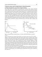
Fig. 7 shows the BER performance for hybrid DF-AF cooperation. For the DF-dominant
hybrid cooperation, the theoretical curves exhibit a good match with the Monte Carlo
simulation results curves. The slight gap between theoretical and simulation BER results for
the hybrid case of 1-DF + multi-AF can be explained by the AF relay fading which was
considered as a double Gaussian channel, a product of two complex Gaussian channel (Patel
et al., 2006). Obviously, the distribution of combined SNR (i.e.,
γ
c
) will no longer follow the
chi-square distribution giving rise to this slight difference.
0 2 4 6 8 10 12 14 16
10
-5
10
-4
10
-3
10
-2
10
-1
Eb/No, dB
Bit Error Rate
BER for BPSK modulation with DF or AF cooperation in Rayleigh channel
direct transmission (sim)
direct transmission (theory)
2-DF cooperation (sim)
2-DF cooperation (theory)
3-DF cooperation (sim)
3-DF cooperation (theory)
2-AF cooperation (sim)
2-AF cooperation (theory)
3-AF cooperation (sim)
3-AF cooperation (theory)
Fig. 6. BER performance for DF or AF cooperation.
OFDM Communications with Cooperative Relays
65
In this proposed hybrid cooperation protocol, DF is dominant. We show this characteristic
of the hybrid DF-AF cooperation by the following theorem:
Theorem 1: For the F-hop relay link, and the full decoding in DF protocol, as long as the SNR
of the last hop is larger than 1/
F times of the arithmetic mean of the whole link SNR, DF
always plays a more important role than AF in improving the BER performance.
0 5 10 15 20
10
-5
10
-4
10
-3
10
-2
10
-1
Eb/No, dB
Bit Error Rate
BER for BPSK modulation with DF-AF hybrid cooperation in Rayleigh channel
1-DF+1-AF cooperation (sim)
1-DF+1-AF cooperation (theory)
1-DF+2-AF cooperation (sim)
1-DF+2-AF cooperation (theory)
2-DF+1-AF cooperation (sim)
2-DF+1-AF cooperation (theory)
2-DF+2-AF cooperation (sim)
2-DF+2-AF cooperation (theory)
3-DF-1-AF cooperation (sim)
3-DF-1-AF cooperation (theory)
Fig. 7. BER performance for hybrid DF+AF cooperation.
Proof: According to the (22) and (23), the average probability of error P
e
is a decreasing
function w.r.t. combined SNR,
γ
c
. The SNR of the F-hop AF relay link,
AF
γ
, is the 1/F times
of the harmonic mean of
γ
i
, ∀ i ∈ [1, F], i.e. (Hasna & Alouini, 2002),
12
AF
12 1 1
1
, ,
, , , ,
L
L
ii L
i
γγ γ
γ
γ
γγγ γ
−+
=
=
∑
(26)
Using Pythagorean means theorem, the harmonic mean is always smaller than the
arithmetic mean. ■
For instance, in the high SNR region, the second term of (8) can be approximated as the ½
times the harmonic mean of the 2-hop SNR in AF relay link (i.e., 1 is negligible in the
denominator). As in practice, it is very easy for the last hop relay to achieve a SNR larger
than 1/
L times of the arithmetic mean of the whole link SNR, we can only consider the last
hop of the reliably decoded DF protocol. Therefore, under the condition of the correct
decoding, DF can enhance the error probability performance better than AF in the
cooperative relay network.
Communications and Networking
66
This DF dominant hybrid cooperative networks strategy can be verified by the above
simulation results as well. Comparing 2-DF to 2-AF in Fig. 6, or 2-DF plus 1-AF to 1-DF plus
2-AF in Fig. 7, or other hybrid DF-AF protocols with the same
R, we can see that the fully
decoded DF protocols always show a better BER performance than AF protocols. Therefore,
DF protocols with a reliable decoding play a more important role in hybrid cooperative
networks than AF protocols. Meanwhile, we can see from the figure that, changing to the AF
scheme for the relay nodes with SNR below the threshold also improves the BER
performance, as well as the diversity gain of the whole network. In fact, this is a better way
than just discarding these relay nodes.
S D
R
2
R
R
DF relay
AF relay
R
1
h
1
h
2
h
4
h
3
S D
R
1
h
1
h
2
h
4
h
3
R
2
S
D
R
1
h
1
h
2
(a)
(b)
(c)
S D
R
2
R
R
DF relay
AF relay
R
1
h
1
h
2
h
4
h
3
S D
R
1
h
1
h
2
h
4
h
3
R
2
S
D
R
1
h
1
h
2
(a)
(b)
(c)
Fig. 8. hybrid DF-AF cooperation and DF cooperation architectures with
different average
power gains. (a) hybrid DF-AF cooperation, (b) dual DF cooperation, (c) single DF
cooperation. (
S: Source, D: Destination, h: average power gain between two nodes).
Reference (Louie et al., 2009) proposes a closed-form BER expression for two-hop AF
protocol, which includes Gauss’ hypergeometric and Gamma functions. This closed-form
BER expression needs more computational burden to derive the cooperative analytical
expression. In (Sadek et al., 2007), the analytical expression for multi-node DF protocol is
provided with a complicated form as well. Instead, the compact closed-form BER expression
for hybrid DF-AF cooperation proposed in this chapter allows us to achieve insight into the
results with relatively low computations. The simple expressions can also help
understanding the factors affecting the system performance. It can also be used for
designing different network functions such as power allocation, scheduling, routing, and
node selection.
In order to study the effect of the channel gains between source, relay and destination, we
compare the hybrid DF-AF with the dual DF as well as the single DF cooperation in Fig. 8.
In this figure,
h
1
, h
2
, h
3
and h
4
stand for the average power gain between corresponding two
nodes. In this simulation, the SNR threshold for correct decoding is assumed to be 4
E
b
/N
0
,
and we set the first hop average power gain in DF protocol, i.e.,
h
1
in Fig. 8 (a) and Fig. 8 (c),
and
h
1
, h
3
in Fig. 8 (b) as 4, which means that the relay in DF protocol can fully decode the
signal. The average power gains of the first hop in AF protocol, i.e.,
h
3
in Fig. 8 (a) increases
OFDM Communications with Cooperative Relays
67
from 0.25 to 20. It can be seen from the Fig. 9 that the dual DF cooperation with reliable
decoding outperforms the hybrid DF-AF cooperation, when corresponding average power
gains are the same, i.e., diamond marked curve is better than square marked curve in Fig. 9.
Meanwhile, the comparison of the curves shows that, the AF relay which undergoes the
deep fading deteriorates the BER performance of hybrid DF-AF cooperation in the low SNR
region. Thus, this AF relay should be removed according to the proposed dynamic optimal
combination strategy to improve the transmission performance. Sum up the above
discussion, due to power control, long transmission range, serious attenuation, etc., high
SNR at relay and full decoding for DF protocol is not always available. In this case, relays
can change to AF protocol with enough SNR to gain from the cooperative diversity.
0 2 4 6 8 10 12 14 16 18 20
10
-5
10
-4
10
-3
10
-2
10
-1
Eb/No, dB
Bit Error Rate
BER for BPSK modulation with Maximal Ratio Combining in Rayleigh channel
h1=4, h2=4, signal DF
h1=4, h2=4, h3=0.25, h4=4, hybrid DF+AF
h1=4, h2=4, h3=1, h4=4, hybrid DF+AF
h1=4, h2=4, h3=4, h4=4, hybrid DF+AF
h1=4, h2=4, h3=20, h4=5, hybrid DF+AF
h1=4, h2=4, h3=4, h4=1, dual DF
h1=4, h2=4, h3=4, h4=4, dual DF
Fig. 9. BER performance for hybrid DF-AF cooperation and DF cooperation with different
path gains.
Finally, we illustrate the validity of the theoretical results for the OFDM cooperation via
simulations. An OFDM system with 64-point FFT and a CP length of 16 samples, which
accounts for 25% of the OFDM symbol was considered. In the simulation, a more practical
scenario was considered with a 3-path Rayleigh fading between each source node and relay
node or relay node and destination node, i.e.,
W
r
= 3. The 3-path delays were assumed at 0,
1, 2 samples, respectively. As illustrated in the Fig. 10, OFDM with CP can nicely cope with
the multi-path, and the theoretical curves derived from (22) clearly agree with the Monte
Carlo simulation curves. The simulation results indicate that under the condition of ISI
resolved by OFDM and reliable decoding, the cooperative diversity gains from the
increasing
R, which is also shown by (8).
Communications and Networking
68
0 5 10 15 20 25 30
10
-5
10
-4
10
-3
10
-2
10
-1
10
0
Eb/No, dB
Bit Error Rate
BER for BPSK using OFDM with DF dominant cooperation in a 3-path Rayleigh channel
1-DF transmission (theory)
1-DF transmission (sim)
2-DF cooperation (theory)
2-DF cooperation (sim)
2-DF+1-AF cooperation (theory)
2-DF+1-AF cooperation (sim)
Fig. 10. BER performance for DF dominant OFDM cooperation.
4. ZP-OFDM with cooperative relays
4.1 CP and ZP for cooperative OFDM
Among the many possible multicarrier modulation techniques, OFDM is the one that has
gained more acceptance as the modulation technique for high-speed wireless networks and
4G mobile broadband standards. Conventionally, CP is exploited to eliminate inter-symbol-
interference (ISI) due to multipath. With a cyclic extension, the linear convolution channel is
transformed into a circular convolution channel, and the ISI can be easily resolved.
However, the cyclic prefix is not the only solution to combat the multipath. ZP has been
recently proposed as an alternative to the CP in OFDM transmissions and Cognitive Radio
(Lu et al., 2009). One of the advantages of using a ZP is that the transmitter requires less
power back-off at the analog amplifier. Since the correlation caused by the cyclic prefix
creates discrete spectral lines (ripples) into the average power spectral density of the
transmitted signal and the radio emission power levels are limited by the Federal
Communications Commission (FCC), the presence of any ripples in the power spectrum
density (PSD) requires additional power back-off at the transmitter. In fact, the amount of
power back-off that is required is equal to the peak-to-average ratio of the PSD.
A multiband (MB) ZP OFDM-based approach to design UWB transceivers has been recently
proposed in (Batra et al., 2004) and (Batra, 2004) for the IEEE Standard. In Dec. 2008, the
European Computer Manufacturers Association (ECMA) adopted ZP-OFDM for the latest
version of High rate UWB Standard (Standard ECMA-368, 2008). Because of its advantage in
the low power transmission, ZP-OFDM will have the potential to be used in other low
power wireless communications systems.
We know that the multiple transmissions in the cooperative system may not be either time
or frequency synchronized, i.e., signals transmitted from different transmitters arrive at the
OFDM Communications with Cooperative Relays
69
receiver as different time instances, and multiple carrier frequency offsets (CFOs) also exist
due to the oscillator mismatching. Different from the conventional MIMO system, the
existence of multiple CFOs in the cooperative systems makes the direct CFOs compensation
hard if not impossible. Therefore, in this section, we will investigate the cooperative ZP-
OFDM system with multipath channel and CFOs, a subject that has not been addressed
before. We propose a STFC, to hold the linear structure of the ZP-OFDM, and achieve the
full cooperative spatial diversity, i.e., full multi-relay diversity. Furthermore, we show that,
with only
linear receivers, such as zero forcing (ZF) and minimum mean square error
(MMSE) receivers, the proposed code achieves full diversity.
4.2 Full cooperative diversity with linear equalizer
4.2.1 Fundamental limits of diversity with linear equalizer
To quantify the performance of different communication systems, two important criteria are
the average bit-error rates (BERs) and capacity. The BER performance of wireless
transmissions over fading channels is usually quantified by two parameters: diversity order
and coding gain (Liu et al., 2003; Tse & Viswanath, 2005). The diversity order is defined as
the asymptotic slope of the BER versus signal-to-noise ratio (SNR) curve plotted in log-log
scale. It describes how fast the error probability decays with SNR, while the coding gain
measures the performance gap among different schemes when they have the same diversity.
The higher the diversity, the smaller the error probability at high-SNR regimes. To cope
with the deleterious effects of fading on the system performance, diversity-enriched
transmitters and receivers have well-appreciated merits. Reference (Ma & Zhang, 2008)
reveals the relationship between the channel orthogonality deficiency (
od) and system full
diversity. The orthogonality deficiency (
od) indicates the degree of difficulty for the signal
detection in the certain transceiver and channel condition (the smaller
od, the easier signal
detection). References (Shang & Xia, 2007; Shang & Xia, 2008) provide the two conditions for
linear equalizer to achieve the full diversity. We will illustrate in this Section how to design
the STFC to achieve full diversity for ZP-OFDM system.
In addition to focusing on diversity performance, practical systems also give high priority to
reducing receiver complexity. Although maximum likelihood equalizer (MLE) enjoys the
maximum diversity performance, its exponential decoding complexity makes it infeasible
for certain practical systems. Some near-ML schemes (e.g., sphere decoding) can be used to
reduce the decoding complexity. However, at low SNR or when large decoding blocks are
sent/or high signal constellations are employed, the complexity of near-ML schemes is still
high. In addition, these near-ML schemes adopt linear equalizers as preprocessing steps. To
further reduce the complexity, when the system model is linear, one may apply linear
equalizers (LEs) (Ma & Zhang, 2008).
4.2.2 System model and Linear ZP-OFDM
We consider a cooperative ZP-OFDM system as shown in the Fig. 11. Here the DF protocol
is adopted in the cooperative communication model. Relays can fully decode the
information, and participate in the cooperation, and occupy different frequency bands to
transmit data to the destination. Each relay-destination link undergoes multipath Rayleigh
fading. For the relay
r, r ∈ [1,2,…,R], R is the number of relays, the received signal y
r
can be
formulated as
,, ,
H
rPrPrrZPNrr
=
+yFDHTFxn
(27)
Communications and Networking
70
where
[]
01
,,
T
rN
xx
−
⋅⋅⋅x is the vector of the so called frequency transmitted information
signal, and
N is the signal length. The subscript r here indicates the variables or operators
related to the
r-th relay. To simplify the exposition, we only consider the effect of CFOs on
signal. The noise term is denoted as
n, which stands for i.i.d. complex white Gaussian noise
with zero mean.
F
N,r
stands for the N-point FFT matrix with (m, k)-th entry
exp( 2 / )/
j
mk N N
π
, while F
P,r
stands for the P-point FFT matrix.
Q
1
Q
r
S
D
···
···
Q
DF relay
Q
2
Q
r+1
Q
R
Q
1
Q
r
S
D
···
···
Q
DF relay
Q
2
Q
r+1
Q
R
Fig. 11. Cooperative ZP-OFDM system architecture, (S: Source, D: Destination, Q
r
: r-th
Relay).
The matrix
0
N
ZP
PN
×
⎡⎤
=
⎢⎥
⎣⎦
I
T
(28)
performs the zero-padding on the transmitted signal with
V zeros, where I
N
is N × N
identity matrix, and
P = N + V.
0
0
ˆ
r
T
0
0
,Pr
D
,Tr
H
0
0
ˆ
r
T
0
0
ˆ
r
T
0
0
,Pr
D
,Tr
H
Fig. 12. Structure of (left)
,Pr
D and (right)
,Tr
H matrix. Blank parts are all 0’s.
OFDM Communications with Cooperative Relays
71
The matrix H
r
is a P × P lower triangular matrix with its first column vector is
1, ,
,, ,0 0
T
rLr
hh
⎡⎤
⋅⋅⋅ ⋅⋅⋅
⎣⎦
, and its first row vector is
1,
,0 0
r
h
⎡
⎤
⋅
⋅⋅
⎣
⎦
, and this matrix denotes the
multipath channel over the r-th relay and destination link, L is the length of channel.
Without loss of generality, we assumed that the channel lengths of different relay-
destination links are all L. To avoid ISI, we should have L ≤ V, and we assume L = V. The
D
P,r
is a diagonal matrix representing the residual carrier frequency error over the r-th relay
and destination link and is defined in terms of its diagonal elements as
(
)
1
,
diag 1, , ,
P
Pr r r
αα
−
=⋅⋅⋅D , with
(
)
exp 2 /
rr
jq
N
απ
=Δ,
(
)
dia
g
⋅
is diagonal matrix with
main diagonal
(
)
⋅ , and
r
q
Δ
is the normalized carrier frequency offset of r-th relay with the
symbol duration of ZP-OFDM. Here, we notice that
,Tr r ZP
=
HHT is a full column rank tall
Toeplitz matrix, and its correlation matrix always guaranteed to be invertible. The structures
of
,Pr
D and
,Tr
H can be shown as Fig. 12.
Since
,Tr
H relates to the linear convolution, we refer to this tall Toeplitz structure as linear
structure, which assures symbol recovery (perfect detectability in the absence of noise)
regardless of the channel zeros locations. The linear structure of ZP-OFDM provides a better
BER performance and an easier blind channel estimation and blind symbol synchronization
as well, while this is not the case for the CP-OFDM. In fact, the channel-irrespective symbol
detectable property of ZP-OFDM is equivalent to claiming that ZP-OFDM enjoys maximum
diversity gain. Intuitively, this can be understood as the ZP-OFDM retains the entire linear
convolution of each transmitted symbol with the channel. Then, we will show how to use
the linear property of
,Tr
H to achieve full spatial diversity in the cooperative system.
Consequently, (27) can be rewritten as
,,,,
H
rPrPrTrNrr
=
+yFDHFxn
(29)
In this section, we consider a simple frequency division space frequency system for each
relay
x
r
, i.e., arranging transmitted symbols in different frequency bands according to the
corresponding relay, as shown in the Fig. 13. By doing so, we can exploit the linear structure
of ZP-OFDM to achieve the full cooperative diversity with linear receiver regardless of the
existence of CFOs.
Q
1
Q
r
···
Q
DF relay
Q
2
Q
r+1
Q
R
···
··· ···
Band 1 Band 2 Band r Band r +1 Band R
Frequency domain
Q
1
Q
r
···
Q
DF relay
Q
2
Q
r+1
Q
R
···
··· ···
Band 1 Band 2 Band r Band r +1 Band R
Frequency domain
Fig. 13. Frequency division cooperative ZP-OFDM system.
Communications and Networking
72
We take x
r
as the information symbols correctly received at the r-th relay nodes involved in
the DF-cooperative scheme. After full decoding,
x
r
is assigned to the corresponding r-th
frequency band as shown in the Fig. 13, and forwarded to the destination.
Considering the frequency division system, the received signal at the destination of all R
relay nodes yields
H
PN
=
+
y
FDHF x n
(30)
where
(
)
,1 , 2 ,
diag , , ,=⋅⋅⋅
P
PP PR
FFFF
,
(
)
,1 ,2 ,
diag , , ,
PP PR
=⋅⋅⋅DDDD
,
(
)
,1 ,2 ,
diag , , ,
TT TR
=⋅⋅⋅HHHH
,
(
)
,1 ,2 ,
diag , , ,
HHHH
NNNNR
=⋅⋅⋅FFFFare all diagonal matrices with each relay’s components on their
diagonals. For instance, we consider a 2-relay cooperation system, i.e., R = 2, the structures
of
P
F
, D, H and
H
N
F can be illustrated as Fig. 14. In (30),
12
,,,
T
TT T
R
⎡
⎤
=⋅⋅⋅
⎣
⎦
xxx x denotes the
forwarded signal from all relays occupying different frequency bands.
If we denote
H
PN
= F DHFH
, then (30) becomes
=
+yxnH (31)
On the other hand, let us go back to (27), right multiplying
ZP
T changes
r
H from a P × P
lower triangular matrix into a P × N tall Toeplitz matrix
,Tr
H with its first column vector as
1, ,
,, ,0 0 ,
T
rLr
hh
⎡⎤
⋅⋅⋅ ⋅⋅⋅
⎣⎦
and we denote
,,
H
tr Nr r
=xFx, which is well known as time domain
signal in OFDM system, then (27) can be represented as
,,,,rPrPrTrtr
=
+yFDHx n (32)
where
,,Tr tr
Hxstands for the linear convolution of the multipath channel with the time
domain transmitted signal, this is a special property possessed by the ZP-OFDM system.
According to the commutativity of the linear convolution, we have
,, ,Tr tr Tr r
=
Hx Xh, where
,Tr
X is a P × L tall Toeplitz matrix with
,
,
T
TT
tr
⎡
⎤
⎣
⎦
x0as its first column, and
1, ,
,,
T
rrLr
hh
⎡⎤
=⋅⋅⋅
⎣⎦
h . Consequently, (32) can be transformed into another form as
,,,rPrPrTrr
=
+yFDXhn (33)
We denote
12
,,,
T
TT T
cR
⎡
⎤
=⋅⋅⋅
⎣
⎦
hhh h,
,,,rPrPrTr
=
SFDX,
(
)
12
diag , , ,
R
=⋅⋅⋅SS SS , and consider
the received signal of all R relay nodes, then we get the received signal as
c
=
+yhnS
(34)
Equations (31) and (34) are two equivalent received data models of this frequency division
cooperative ZP-OFDM system.
H in (31) is regarded as the overall equivalent channel,
while
S in (34) is the equivalent signal matrix of this frequency division cooperative ZP-
OFDM system. In the following section, we will exploit
H and
c
h from (31) and (34) to
show the verification of the full cooperative spatial diversity.
OFDM Communications with Cooperative Relays
73
0
0
0
0
P
F
D
H
H
N
F
,1
P
F
,2
P
F
,1
P
D
,2
P
D
,1T
H
,2T
H
0
0
,1
H
N
F
,2
H
N
F
0
0
0
0
0
0
P
F
D
H
H
N
F
,1
P
F
,2
P
F
,1
P
D
,2
P
D
,1T
H
,2T
H
0
0
,1
H
N
F
,2
H
N
F
0
0
Fig. 14. Structures of the FFT matrices, CFOs matrix and channel matrix for 2-relay
cooperative system, top left: FFT matrix
P
F , top right: CFOs matrix D, bottom left: channel
matrix:
H, bottom right: FFT matrix
H
N
F . Blank parts are all 0’s.
4.3 Space time frequency coding design
4.3.1 Conditions of the full diversity with linear equalizer
In this section, we will show how linear receiver is the only required to achieve full
cooperative diversity order RL. We first cite the following theorem from (Shang & Xia, 2007;
Shang & Xia, 2008):
Theorem 2 (Shang & Xia, 2007; Shang & Xia, 2008): For PAM, PSK and square QAM
constellations, if the following condition holds
c
α
≤ hH and
(
)
2
det
N
H
c
β
≥ hHH
where
α
and
β
are positive constants independent of
c
h ,
⋅
is the Frobenius norm of a
vector/matrix, and N is the number of symbols in the transmitted signal, i.e., the length of