Advances in Gas Turbine Technology Part 1 ppt
Bạn đang xem bản rút gọn của tài liệu. Xem và tải ngay bản đầy đủ của tài liệu tại đây (734.78 KB, 30 trang )
ADVANCES IN GAS
TURBINE TECHNOLOGY
Edited by Ernesto Benini
Advances in Gas Turbine Technology
Edited by Ernesto Benini
Published by InTech
Janeza Trdine 9, 51000 Rijeka, Croatia
Copyright © 2011 InTech
All chapters are Open Access distributed under the Creative Commons Attribution 3.0
license, which permits to copy, distribute, transmit, and adapt the work in any medium,
so long as the original work is properly cited. After this work has been published by
InTech, authors have the right to republish it, in whole or part, in any publication of
which they are the author, and to make other personal use of the work. Any republication,
referencing or personal use of the work must explicitly identify the original source.
As for readers, this license allows users to download, copy and build upon published
chapters even for commercial purposes, as long as the author and publisher are properly
credited, which ensures maximum dissemination and a wider impact of our publications.
Notice
Statements and opinions expressed in the chapters are these of the individual contributors
and not necessarily those of the editors or publisher. No responsibility is accepted for the
accuracy of information contained in the published chapters. The publisher assumes no
responsibility for any damage or injury to persons or property arising out of the use of any
materials, instructions, methods or ideas contained in the book.
Publishing Process Manager Alenka Urbancic
Technical Editor Teodora Smiljanic
Cover Designer Jan Hyrat
Image Copyright Dmitry Skutin, 2010. Used under license from Shutterstock.com
First published October, 2011
Printed in Croatia
A free online edition of this book is available at www.intechopen.com
Additional hard copies can be obtained from
Advances in Gas Turbine Technology, Edited by Ernesto Benini
p. cm.
ISBN 978-953-307-611-9
free online editions of InTech
Books and Journals can be found at
www.intechopen.com
Contents
Preface IX
Part 1 Aero and Marine Gas Turbines 1
Chapter 1 Future Aero Engine Designs: An Evolving Vision 3
Konstantinos G. Kyprianidis
Chapter 2 State-of-Art of Transonic Axial Compressors 25
Roberto Biollo and Ernesto Benini
Chapter 3 Possible Efficiency Increasing
of Ship Propulsion and Marine Power Plant
with the System Combined of Marine Diesel
Engine, Gas Turbine and Steam Turbine 45
Marek Dzida
Part 2 Gas Turbine Systems 69
Chapter 4 Exergy Analysis of
a Novel SOFC Hybrid System with Zero-CO
2
Emission 71
Liqiang Duan, Xiaoyuan Zhang and Yongping Yang
Chapter 5 Flexible Micro Gas Turbine Rig
for Tests on Advanced Energy Systems 89
Mario L. Ferrari and Matteo Pascenti
Chapter 6 Biofuel and Gas Turbine Engines 115
Marco Antônio Rosa do Nascimento and Eraldo Cruz dos Santos
Chapter 7 Afterburning Installation Integration into
a Cogeneration Power Plant with Gas Turbine
by Numerical and Experimental Analysis 139
Ene Barbu, Valeriu Vilag, Jeni Popescu, Silviu Ionescu,
Adina Ionescu, Romulus Petcu, Cleopatra Cuciumita,
Mihaiella Cretu, Constantin Vilcu and Tudor Prisecaru
VI Contents
Chapter 8 Application of Statistical Methods
for Gas Turbine Plant Operation Monitoring 165
Li Pan
Part 3 Heat Transfer 189
Chapter 9 Jet Impingement Cooling in Gas Turbines
for Improving Thermal Efficiency and Power Density 191
Luai M. Al-Hadhrami, S.M. Shaahid and Ali A. Al-Mubarak
Chapter 10 Influence of Heat Transfer
on Gas Turbine Performance 211
Diango A., Périlhon C., Danho E. and Descombes G.
Part 4 Combustion 237
Chapter 11 Developments of Gas Turbine Combustors
for Air-Blown and Oxygen-Blown IGCC 239
Takeharu Hasegawa
Chapter 12 Characterization of a Spray in the Combustion
Chamber of a Low Emission Gas Turbine 267
Georges Descombes
Part 5 Materials and Fabrication 291
Chapter 13 Materials for Gas Turbines – An Overview 293
Nageswara Rao Muktinutalapati
Chapter 14 Titanium in the Gas Turbine Engine 315
Mark Whittaker
Chapter 15 Platinum-Based Alloys and Coatings:
Materials for the Future? 337
Lesley A. Cornish and Lesley H. Chown
Chapter 16 Unidirectionally Solidified Eutectic Ceramic Composites
for Ultra-High Efficiency Gas Turbine Systems 371
Yoshiharu Waku
Chapter 17 Study of a New Type High Strength
Ni-Based Superalloy DZ468 with
Good Hot Corrosion Resistance 399
Enze Liu and Zhi Zheng
Chapter 18 BLISK Fabrication by Linear Friction Welding 411
Antonio M. Mateo García
Contents VII
Chapter 19 Damageability of Gas Turbine Blades
– Evaluation of Exhaust Gas Temperature
in Front of the Turbine Using a Non-Linear Observer 435
Józef Błachnio and Wojciech Izydor Pawlak
Chapter 20 New Non-Destructive Methods
of Diagnosing Health of Gas Turbine Blades 465
Józef Błachnio, Mariusz Bogdan and Artur Kułaszka
Chapter 21 Repair of Turbine Blades Using Cold Spray Technique 499
Kazuhiro Ogawa and Dowon Seo
Preface
World energy demand is likely to increase over the next 20 years, and it is well
ascertained that fossil fuels will still be the dominant source for power generation all
over the world. In this scenario, gas turbine (GT) engines will still represent a key
technology, either in stand-alone applications or combined with other power
generation equipment.
The challenges in GT technology today deal with several issues, such as increased
on/off design efficiency, reduced performance degradation over time, and decreased
pollutant emissions levels. Major research efforts and investments are being bestowed
for the development of new, advanced GT technologies with superior performance,
thus helping in the fulfillment of the Kyoto Protocol objectives for greenhouse gases
reduction, as well as of many other transnational policies on sustainability and
reduced environmental impact of energy technologies.
The book intends to provide an updated picture, as well as a perspective view of some
of the major improvements which characterize the GT technology in different
applications, from marine and aircraft propulsion to industrial and stationary power
generation. Therefore, the target audience for it involves design, analyst, materials and
maintenance engineers. Manufacturers, researchers and scientists will also benefit
from the timely and accurate information provided.
The book is organized into five main sections, which are comprised of 21 chapters: (I)
Aero and Marine Gas Turbines, (II) Gas Turbine Systems, (III) Heat Transfer, (IV)
Combustion, and (V) Materials and Fabrication. Starting from a general but evolving
vision on GT and their components used in aircraft and marine engines in Section I, a
systematic approach is used in Section II to describe the thermodynamic behavior of
various GT-based technologies, including combined power, hybrid fuel cell/GT and
small-scale GT plants. Then, in Sections III and IV, a total of four specific works (two
articles each) are included, which present some of the latest developments in the
internal heat transfer and combustion-related phenomena. Finally, a collection of nine
papers in Section V. deal with the most recent advances regarding the new materials
for GT component fabrication, including interesting suggestions on material damage
prevention, diagnosis and repair.
X Preface
The editor is indebted to all the valuable contributions included in this book from the
various GT experts spread worldwide, as well as to InTech Open Access Publisher for
giving me the opportunity to edit this volume, and supporting me constantly during
its preparation.
Dr. Ernesto Benini
Department of Mechanical Engineering
University of Padova,
Italy
Part 1
Aero and Marine Gas Turbines
0
Future Aero Engine Designs: An Evolving Vision
Konstantinos G. Kyprianidis
Chalmers University of Technology
Sweden
1. Introduction
Public awareness and political concern over the environmental impact of civil aviation growth
has improved substantially during the past 30 years. As the environmental awareness
increases, so does the effort associated with addressing NO
x
and CO
2
emissions by all the
parties involved. In the Vision 2020 report made by the Advisory Council for Aeronautical
Research in Europe (2001), goals are set to reduce noise and emissions produced by the ever
increasing global air traffic. Emissions legislation, set by the International Civil Aviation
Organisation (ICAO) and it’s Committee on Aviation Environmental Protection (CAEP), is
becoming ever more stringent, creating a strong driver for investigating novel aero engine
designs that produce less CO
2
and NO
x
emissions.
On the other hand, airline companies need to continuously reduce their operating costs in
order to increase, or at least maintain, their profitability. This introduces an additional design
challenge as new aero engine designs need to be conceived for reduced environmental impact
as well as direct operating costs. Decision making on optimal engine cycle selection needs to
consider mission fuel burn, direct operating costs, engine and airframe noise, emissions and
global warming impact.
CO
2
emissions are directly proportional to fuel burn, and therefore any effort to reduce them
needs to focus on improving fuel burn, by reducing engine Specific Fuel Consumption (SFC),
weight and size. Reducing engine weight results in a lower aircraft maximum take-off weight,
which in turn leads to reduced thrust requirements for a given aircraft lift to drag ratio.
Reducing engine size – predominantly engine nacelle diameter and length – reduces nacelle
drag and therefore also leads to reduced thrust requirements. For a given engine SFC, a
reduction in thrust requirements essentially results in lower fuel burn. Lower engine SFC can
be achieved by improving propulsive efficiency and thermal efficiency – either by reducing
component losses or by improving the thermodynamic cycle.
Improvements in propulsive efficiency – and hence engine SFC at a given thermal efficiency
– can be achieved by designing an engine at a lower specific thrust (i.e. net thrust divided by
fan inlet mass flow). This results in a larger fan diameter, at a given thrust, and therefore
in increased engine weight, which can partially, or even fully, negate any SFC benefits.
Propulsive efficiency improvements at a constant weight are directly dependent on weight
reduction technologies such as light weight fan designs and new shaft materials. Increasing
engine bypass ratio aggravates the speed mismatch between the fan and the low pressure
turbine. Introduction of a gearbox can relieve this issue by permitting the design of these two
1
2 Will-be-set-by-IN-TECH
components at their optimal speeds, and can hence reduce engine weight, as well as improve
component efficiency. The first research question therefore rises:
How low can we really go on specific thrust?
Improvements in thermal efficiency – and hence engine SFC at a given propulsive efficiency –
can be achieved for conventional cores mainly by increasing engine Overall Pressure Ratio
(OPR). At a given OPR there is an optimal level of combustor outlet temperature T
4
for
thermal efficiency. However, at a fixed specific thrust and engine thrust, an increase in T
4
can result in a smaller core and therefore a higher engine bypass ratio; in some cases, a
potential reduction in engine weight can more than compensate for a non-optimal thermal
efficiency. Increasing OPR further than current engine designs is hindered by limitations
in high pressure compressor delivery temperature at take-off. Increasing T
4
is limited by
maximum permissable high pressure turbine rotor metal temperatures at take-off and top of
climb. Increasing turbine cooling flows for this purpose is also fairly limited as a strategy;
cooling flows essentially represent losses in the thermodynamic cycle, and increasing them
eventually leads to severe thermal efficiency deficits (Horlock et al., 2001; Wilcock et al., 2005).
Designing a combustor at very low air to fuel ratio levels is also limited by the need for
adequate combustor liner film-cooling air as well as maintaining an acceptable temperature
traverse quality (Lefebvre, 1999). The second research question therefore rises:
How high can we really go on OPR and T
4
?
Aggressive turbofan designs that reduce CO
2
emissions – such as increased OPR and T
4
designs – can increase the production of NO
x
emissions due to higher flame temperatures.
The third research question therefore rises:
What is the trade-off between low CO
2
and NO
x
?
The research work presented in this chapter will focus on identifying several novel engine
cycles and technologies - currently under research - that can address the three research
questions raised. These concepts will be evaluated based on their potential to reduce CO
2
and NO
x
emissions for engine designs entering service between 2020 and 2025. Design
constraints, material technology, customer requirements, noise and emissions legislation,
technology risk and economic considerations and their effect on optimal concept selection
will also be discussed in detail.
2. An evolving vision
Numerous feasibility studies have been published over the years focusing on future engine
and aircraft designs that can reduce fuel consumption; a brief review of some of these
publications will be carried out here.
One of the earliest discussions on the subject of improving engine fuel efficiency is provided
by Gray & Witherspoon (1976), looking at conventional and heat exchanged cores, as well
as non-steady flow combustion processes and open rotor configurations. A similar study
focusing on geared and open rotor arrangements as well as heat exchanged cycles is presented
by Hirschkron & Neitzel (1976).
An interesting discussion on how specific thrust levels were expected to evolve in the mid-70’s
based on the economic and technological projections of that time period is given by Jackson
4
Advances in Gas Turbine Technology
Future Aero Engine Designs: An Evolving Vision 3
(1976); the author has also provided an update to that discussion based on current economical
and technological projections (Jackson, 2009). Wilde (1978), Young (1979), and Pope (1979)
provide a good reference on how the future for civil turbofan engines for medium and long
range applications was envisaged in the late 70’s. Some early discussions on future trends
in commercial aviation from the aircraft manufacturer’s perspective can be found in Swihart
(1970) and Bates & Morris (1983), while Watts (1978) provides an airliner’s view of the future.
A review on the several technical and economic obstacles that were identified in the late
80’s with respect to the realization of the Ultra-High Bypass Ratio (UHBR) turbofan concept
is provided by Borradaile (1988) and by Zimbrick & Colehour (1988). Peacock & Sadler
(1992) give an update on the subject, focusing further on engine design constraints and
the technology advancements required for producing a competitive UHBR configuration.
Potential year 2020 scenarios are explored by Birch (2000) while an overview of current
aero engine technology and some insight on the future of aircraft propulsion is given
by Ruffles (2000). Sieber (1991) and Schimming (2003) provide an excellent discussion on
counter-rotating fan designs. Finally, for a review on the development of civil propulsion
from the early 50’s to recent years the interested reader is referred to Saravanamuttoo (2002).
The focus of the next section will be given on recent European research initiatives on enabling
technologies relevant to the three research questions that have been set.
3. Enabling technologies and recent research
3.1 Propulsor technologies
Within the EU Framework Program 6 research project VITAL (enVIronmenTALly friendly
aero engines, 2009) a number of low pressure system component technologies have been
investigated (Korsia, 2009; Korsia & Guy, 2007). The emerging progress will allow the design
of new powerplants capable of providing a step reduction in fuel consumption and generated
noise.
The VITAL project concentrated on new technologies for the low pressure system of the
engine, which enable the development of low noise and low weight fan architectures for
UHBR engines. To achieve these objectives, the VITAL project has investigated three different
low pressure configurations, leading to low noise and high efficiency power plants. The
three configurations are the DDTF (Direct Drive TurboFan) supported by Rolls-Royce, the
GTF (Geared TurboFan) by MTU and the CRTF (Counter-Rotating TurboFan) by Snecma.
The DDTF architecture offers a re-optimised trade-off between fan and turbine requirements
considering the low weight technologies introduced by the VITAL programme. The GTF
combines a fan with a reduction gear train, to allow different rotating speeds for the fan on
one hand, and the booster and turbine on the other. The CRTF offers a configuration with two
fans turning in opposite directions, allowing for lower rotational speeds, since the two fan
rotors split the loads involved.
The technologies being built into the VITAL engines include (Korsia, 2009; Korsia & Guy,
2007):
• New fan concepts with the emphasis on two types: counter-rotating and lightweight fans.
• New booster technologies for different operational requirements; low and high speed,
associated aerodynamic technologies, new lightweight materials and associated coating
and noise reduction design.
5
Future Aero Engine Designs: An Evolving Vision
4 Will-be-set-by-IN-TECH
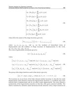
Fig. 1. Effect of fan tip pressure ratio and bypass duct pressure losses on fan equivalent
polytropic efficiency
• Polymer composites and corresponding structural design and manufacturing techniques
are studied in parallel with advances in metallic materials and manufacturing processes.
• Shaft torque density capabilities through the development of metal matrix composites and
multi metallic shafts.
• Low pressure turbine weight savings through ultra high lift airfoil design, ultra high stage
loading, lightweight materials and design solutions.
• Technologies for light weight and low drag installation of high bypass ratio engines related
to nozzle, nacelle and thrust reverser.
The open rotor engine concept, for high subsonic flight speeds, has also risen as a candidate
for improving fuel consumption on several occasions since the advent of the first high bypass
ratio turbofan engine. Such engine configurations, often refereed to as propfans in the
literature, are direct competitors to ultra high bypass ratio turbofan engines. Their are located
at the ultra-low specific thrust region of the design space, where propulsive efficiency benefits
for turbofans are negated by very low transfer efficiencies. As illustrated in Fig. 1, this is due to
the dominant effect on transfer efficiency that bypass duct pressure losses have when looking
at low fan tip pressure ratio engine designs, i.e. low specific thrust. Open rotor engines do
not suffer from bypass duct pressure losses and can therefore achieve a very high propulsive
efficiency at a good level of transfer efficiency. Compared to turbofans, propfans also benefit
from reduced nacelle drag and weight penalties.
Several open rotor programs took place during the 80’s, resulting in engine demonstrators
and flight tests. The purpose of these projects was to develop propfan concepts that could
fly efficiently at speeds comparable to high bypass ratio turbofans, i.e. close to Mach
0.8. General Electric proposed the UDF (UnDucted Fan), a pusher configuration with
counter-rotating propellers driven by a counter-rotating low pressure turbine (GE36 Design
and Systems Engineering, 1987). The 578-DX, a pusher configuration with counter-rotating
6
Advances in Gas Turbine Technology
Future Aero Engine Designs: An Evolving Vision 5
Fig. 2. Compressor efficiency improvement with year of entry into service.
propellers driven by a more conventional low pressure turbine through a differential
planetary differential gearbox, was the result of a joint effort by Pratt & Whitney, Hamilton
Standard, and Allison.
Both projects were eventually put on hold towards the end of the decade as fuel prices
fell significantly. Nevertheless, the open rotor concept has now resurfaced within the EU
Framework Program 7 research project DREAM (valiDation of Radical Engine Architecture
systeMs, 2011) and the Clean Sky Joint Technology Initiative (2011). Within DREAM, the
feasibility of two different open rotor architectures is evaluated including noise. Within Clean
Sky, research work is being carried out by some of Europe’s largest aero engine manufacturers,
such as Rolls-Royce and Snecma, focused on designing, building and testing an open rotor
demonstrator.
3.2 Core technologies
Improving core component efficiencies (including reducing losses in the cycle such as duct
pressure losses) is one way of improving the engine thermal efficiency. Nevertheless, modern
CFD-assisted designs are already quite aggressive and limited benefit may be envisaged by
such future advancements (Kurzke, 2003); the increasing effort required to improve an already
very good axial compressor design is illustrated in Fig.2.
Within the EU Framework Program 6 research project NEWAC (NEW Aero engine Core
concepts, 2011) a number of advanced core component technologies have been investigated
that include (Rolt & Kyprianidis, 2010; Wilfert et al., 2007):
• Improved high pressure compressor aero design and blade tip rub management.
• Flow control technologies including aspirated compression systems.
• Active control of surge and tip clearance in compressors.
• Active control of a cooled cooling air system.
7
Future Aero Engine Designs: An Evolving Vision
6 Will-be-set-by-IN-TECH
Fig. 3. Evolution of turbine material capability and future trend.
As mentioned earlier another way of improving engine thermal efficiency is to raise the
cycle OPR. For conventional cores, increasing OPR and T
4
depends primarily on future
advancements in material and cooling technology. The evolution of turbine material
capability over a period of 50 years is illustrated in Fig. 3. As can be observed, only mild
improvements have been achieved so far and this seems to be a continuing trend; the potential
introduction of ceramics would form a major improvement in the field, but substantially more
research is still required before realising this. Despite the low improvement rate in turbine
material technology (roughly 3 [K/year]) aero engine designs have seen substantial increases
in T
4
over the last 60 years (roughly 10 [K/year]); this is illustrated in Fig. 4 for engines
designed for long-haul applications. The main reason behind these improvements in T
4
has
been the introduction of cooling and Thermal Barrier Coatings (TBC) in turbine designs; the
interested reader is referred to Downs & Kenneth (2009) for a good overview of the evolution
of turbine cooling systems design.
It is perhaps debatable whether an improvement rate of 10 [K/year] in T
4
can be maintained
in the future, and for that reason the design focus for more aggressive thermal efficiency
improvements could very well be redirected to the introduction of heat-exchanged cores and
advanced compressor technologies for future turbofan designs. In that respect, some of the
technologies researched under the NEWAC project can be perceived as intermediate enabling
steps for realising new engine core concepts that could improve the core thermal efficiency.
These new core concepts comprise of:
• Ultra-high OPR core with intercooling.
• Medium OPR intercooled recuperated core.
• High OPR flow controlled core.
• High OPR active core including active cooling air cooling.
When considering intercooling for an aero engine design, a common textbook misconception
is that the thermal efficiency of an intercooled core will always be lower than a conventional
8
Advances in Gas Turbine Technology
Future Aero Engine Designs: An Evolving Vision 7
Fig. 4. Evolution of turbine entry temperature and future trend.
core’s for a fixed OPR and specific thrust (Saravanamuttoo et al., 2001). The argument behind
this is that the heat removed by the intercooler will largely need to be reintroduced in the
combustor by burning more fuel, while the reduction in compression work and increase in
bypass stream thrust (due to the heat rejection) will only partially compensate for the loss in
cycle efficiency, at a fixed specific thrust and T
4
. Adding the expected intercooler pressure
losses in the cycle calculations would further worsen the SFC deficit and make the increase in
specific thrust less marked.
However, cycle calculations based on half-ideal gas properties and no dissociation (i.e.
isobaric heat capacity dependent on temperature), presented by Walsh & Fletcher (1998), give
a slightly different picture on intercooling. For a given T
4
, the optimal OPR for an intercooled
core will be much higher than that for a conventional core. Comparing the two concepts at
their optimal OPR levels, for a given technology level, can make the intercooled core more
attractive with respect to thermal efficiency and not just specific thrust. Canière et al. (2006)
and da Cunha Alves et al. (2001) also reached the same conclusion about the thermal efficiency
of the intercooled cycle while studying this concept for gas turbines used in power generation.
Papadopoulos & Pilidis (2000) worked on the introduction of intercooling, by means of heat
pipes, in an aero engine design for long haul applications. Xu et al. (2007) performed a mission
optimization to assess the potential of a tubular intercooler. Recent work by Xu & Grönstedt
(2010) presents a refined tubular configuration estimating a potential block fuel benefit of
3.4%. The work addresses the limitation that short high pressure compressor blade lengths
and related low compression efficiencies may impose on engines designed for short range
missions, and suggest a novel gas path layout as a remedy to this constraint. A design study
of a high OPR intercooled aero engine is described in Rolt & Baker (2009), while details on the
aerodynamic challenges in designing a duct system to transfer the core air into and out of the
intercooler are presented by Walker et al. (2009).
The introduction of recuperation in an aero engine, for high thermal efficiency at low OPR,
has also been the focus of different researchers. Lundbladh & Sjunnesson (2003) performed
a feasibility study for InterCooled (IC) and Intercooled Recuperated Aero engines (IRA) that
9
Future Aero Engine Designs: An Evolving Vision
8 Will-be-set-by-IN-TECH
consider cycle benefits, weights and direct operating costs. Boggia & Rud (2005) provide
an extended discussion on the thermodynamic cycle and the technological innovations
necessary for realizing the intercooled recuperated core concept. Various aspects of the
thermo-mechanical design of a compact heat exchanger have been presented by Pellischek
& Kumpf (1991) and Schoenenborn et al. (2006). For a comprehensive review on the
development activities for recuperated aero engines since the late 60’s the interested reader
can refer to McDonald et al. (2008a;b;c).
Finally, three different types of lean-burn combustor technology were also researched within
NEWAC with the objective of reducing emissions of oxides of nitrogen (NO
x
):
• Lean Direct Injection (LDI) combustor for high and ultra-high OPR cores.
• Partial Evaporation and Rapid Mixing (PERM) combustor for high OPR cores.
• Lean Premixed Pre-vaporized (LPP) combustor for medium OPR cores.
4. Design space exploration
4.1 Methodology, design feasibility and constraints
To effectively explore the design space a tool is required that can consider the main disciplines
typically encountered in conceptual design. The prediction of engine performance, aircraft
design and performance, direct operating costs, and emissions for the concepts analysed in
this study was made using the EVA code (Kyprianidis et al., 2008). Another code, WeiCo,
was also used for carrying out mechanical and aerodynamic design in order to derive engine
component weight and dimensions. The two tools have been integrated together within an
optimiser environment as illustrated in Fig. 5, based on lessons learned from the development
of the TERA2020 tool (Kyprianidis et al., 2011). This integration allows for multi-objective
optimization, design studies, parametric studies, and sensitivity analysis. In order to speed up
the execution of individual engine designs, the conceptual design tool attempts to minimize
internal iterations in the calculation sequence through the use of an explicit algorithm, as
described in detail by Kyprianidis (2010).
Aero-engine designs are subject to a large number of constraints and these need to be
considered during conceptual design. Constraints can be applied within the optimiser
environment at the end of the calculation sequence i.e., after the last design module has
been executed. During a numerical optimisation, the optimiser will select a new set of input
design parameters for every iteration and the resulting combination of aircraft and engine
will be assessed. Using user specified objective functions the optimiser will home in on
the best engine designs, determining the acceptability/feasibility of each design through the
constraints set by the user. Infeasible designs will be ruled out, while non-optimum design
values will result in engine designs with non-optimum values for the objective function
selected. The optimiser will therefore avoid regions in the design pool that result in infeasible
or non-optimum engine designs.
Design constraints set by the user include among others:
• Take-off HPC delivery temperature and other important performance parameters.
• FAR (Federal Aviation Regulations) take-off field length for all engines operating and
balanced field length for one engine inoperative conditions.
• Time to height.
10
Advances in Gas Turbine Technology
Future Aero Engine Designs: An Evolving Vision 9
Fig. 5. Conceptual design tool algorithm (Kyprianidis, 2010).
• LTO (Landing and Take-Off) cycle D
p
NO
x
/F
oo
vs. ICAO certification limits and CAEP
medium and long term goals.
• Cumulative EPNL vs. ICAO certification limits.
• Engine time between overhaul.
Where component design is concerned, for a conventional core the High Pressure Compressor
(HPC) delivery temperature, and hence the engine OPR, is typically constrained by the
mechanical properties of the HPC disc or HPC rear drive cone or High Pressure Turbine
(HPT) disc material (Rolt & Baker, 2009). For an intercooled core, the OPR value is no
longer constrained by a maximum allowable HPC delivery temperature. Nevertheless, the
intercooling process increases the air density in the gas path and as a result the compressor
blades tend to become smaller. Losses from tip clearances become increasingly important
and a minimum compressor blade height limitation needs to be applied to maintain state of
the art compressor efficiency. Core architecture selections for the conventional core set an
upper limit to the HPC design pressure ratio that can achieved when driven by a single-stage
HPT. A transonic single-stage HPT design can allow for relatively higher HPC pressure
ratios at the expense of a lower polytropic efficiency. A two-stage HPT can offer high
HPC pressure ratios at a high polytropic efficiency but a trade-off arises with respect to the
need for more cooling air and increased engine length associated with the introduction of a
second row of vanes and blades. With respect to the intercooled core, the minimum design
pressure ratio for the Intermediate Pressure Compressor (IPC) can in some cases be limited
by icing considerations during the descent flight phase. The maximum area variation that
may be achieved by the variable area auxiliary nozzle is also constrained by mechanical (and
aerodynamic) considerations.
11
Future Aero Engine Designs: An Evolving Vision
10 Will-be-set-by-IN-TECH
As discussed earlier, designing a combustor at very low air to fuel ratio levels is also limited
by the need for adequate combustor liner film-cooling air as well as maintaining an acceptable
temperature traverse quality (Lefebvre, 1999); this sets an upper bound on combustor outlet
temperature. Furthermore, a maximum permissible mean metal temperature needs to be set to
consider turbine blade material limitations. A lower bound on engine time between overhaul
also needs to be set to limit the frequency of workshop visits. For short range applications
the minimum engine time between overhaul was set to 18000 [hr] while for long range
applications to 23000 [hr]. This reflects the fact that designs for short range applications are
typically operated at high power conditions for a significantly larger part of their operational
life. Significantly lower levels of maximum combustor outlet temperature and turbine blade
mean metal temperature had to be selected, compared to what could be selected for engine
designs for long range applications that are often operated at derated thrust levels and spend
most of their life at cruise.
A rubberised aircraft wing model was used in these studies to capture ’snowball effects’
with respect to maximum take-off weight variation, rather than using fixed engine thrust
requirements. The aircraft drag polar and weight breakdown were predicted at component
level from the aircraft geometry and high lift device settings for the take-off and approach
phases. Fuel burned was calculated for the entire flight mission including reserves assuming
ISA conditions, as illustrated in Fig. 6. Cruise is performed at the optimum altitude for specific
range (fixed cruise Mach number) using a step-up cruise procedure as the aircraft gets lighter.
A comprehensive take-off field length calculation is performed for all engines operating and
one engine inoperative conditions up to 1500 [ft].
Two baseline aircraft models have been used herein; one model for long range applications
and one for short range. The former model is largely based on public domain information
available for the Airbus A330-200 while the latter model is based on the Airbus A320-200. The
short range aircraft was designed to carry 150 [pax] for a distance of 3000 [nmi] and a typical
business case of 500 [nmi]; for long range applications it was designed for 253 [pax], 6750 [nmi]
and 3000 [nm], respectively. For the step-up cruise procedure, a minimum residual rate of
climb of 300 [ft/min] was set as a constraint for flying at the cruise altitude for maximum
specific range.
The maximum values for FAR take-off field length and time to height were set for a load factor
of 1 and no cargo. The choice of both is based on customer operational requirements as the
aircraft needs to be able to: (i) take-off from a large number of airports around the world
and (ii) climb to the initial cruise altitude sufficiently fast to ease operations with local air
traffic control (and hence reduce waiting time on the ground). A cumulative distribution of
the world’s major runway lengths, based on data from Jenkinson et al. (1999), is illustrated
in Fig. 7. For short range applications fairly stringent constraints are typically set for the
maximum take-off distance and time to height; in this study these were set to 2.0 [km] and 25
[min], respectively. For long range applications a maximum take-off distance of 2.5 [km] was
set instead. Stringent constraints result in bigger engines but allow for greater flexibility for
engine derating at a smaller block fuel cost.
The choice of load factor and cargo is considered sensible but it does not necessarily constitute
a typical airline practice. Validating absolute block fuel predictions with public domain airline
data is not a trivial task as different airlines will follow different operational practices. For
example for the long range aircraft model, the business case prediction is 10% lower than
the published annually-averaged value, given in [lt/(km*pax)], by SwissAir for 2009 for the
12
Advances in Gas Turbine Technology
Future Aero Engine Designs: An Evolving Vision 11
Fig. 6. Typical flight cycle.
Airbus A330-200 (Swiss International Air Lines, 2009). This does not necessarily mean that
the model’s business case is not a realistic one; nor that it wouldn’t fit well with operational
practices followed by other airlines. Furthermore, regional Air Traffic Management (ATM)
practices can skew available block fuel data, while global ATM regulations may very well
change significantly by 2020. It should be noted that fuel planning within the model respects
the requirements defined for international flights by Federal Aviation Administration (n.d.)
and Joint Aviation Authorities (2008).
Where conceptual design is concerned, exchange rates are perhaps a better type of parameter
for evaluating the accuracy of a rubberised wing model, rather than just simply comparing
absolute values. Block fuel exchange rates produced with the rubberised wing baseline
aircraft models are presented in Table 1 for the business case of the long and short range
models and are considered reasonable numbers.
During a block fuel optimization all engine aircraft combinations which do not fulfil the
take-off and time to height criteria set will be discarded as infeasible. Due to the underlying
physics, this will naturally lead to an optimal engine and aircraft combination for the defined
objective function. All large engines will produce heavier aircraft with more drag and thus
higher block fuel weight. Engines which are too small will not deliver enough thrust to satisfy
the take-off and time to height criteria set.
13
Future Aero Engine Designs: An Evolving Vision