Heat Transfer Theoretical Analysis Experimental Investigations and Industrial Systems part 3 pptx
Bạn đang xem bản rút gọn của tài liệu. Xem và tải ngay bản đầy đủ của tài liệu tại đây (1.9 MB, 40 trang )
Heat Transfer - Theoretical Analysis, Experimental Investigations and Industrial Systems
70
Fig. 29. Temperature variation in the CPU cooling system
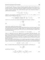
In order to conduct the calculations we used the mathematical model proposed by J.P.
Holman (Simons, 2004, Guenin, 2003). The area and the perimeter of the radiator are:
(
)
2
bf fff
A
rea w h h N t h m
⎡
⎤
=⋅ + − ⋅⋅
⎣
⎦
(8)
(
)
(
)
22[]
bf ff f
Perimeter w h h N t h m=⋅ + + + ⋅ +⋅
(9)
Calculate hydraulic diameter of heat sink/shroud passage area:
[]
4
hyd
Area
Dm
Perimeter
⋅
=
(10)
Holman indicates the initial use of a certain “guess value”, marked as Vel. We gave this Vel
an initial value Vel=0.2. The same author indicates the use of the relation below:
1
3
2
64
hs
hs
ap
hh
gPh
VrootVel Vel
h
nu
T Area C K
Vel D D
ρ
⎡
⎤
⎡⎤
⎡⎤
⎢
⎥
⎢⎥
⎢⎥
⎢
⎥
⎢⎥
⋅⋅
⎢⎥
⎢
⎥
⎢⎥
=−⋅ ⋅
⎢⎥
⎢
⎥
⎢⎥
⎡⎤
⎡⎤
⋅
⎢⎥
⎢
⎥
⎢⎥
⋅⋅⋅ ⋅+
⎢⎥
⎢⎥
⎢⎥
⋅
⎢
⎥
⎢⎥
⎢⎥
⎣⎦
⎣⎦
⎣⎦
⎢
⎥
⎢⎥
⎣⎦
⎣
⎦
(11)
Calculate Reynolds’ number:
Re
hyd
D
V
nu
=⋅
(12)
The frictional heating factor between two reciprocating parts in contact is:
64
Re
f =
(13)
Reynolds’ value on the direction of air flow in the radiator has the following expression:
Heat Transfer in Minichannels and Microchannels CPU Cooling Systems
71
Re
hs
x
Wh
nu
⋅
= (14)
Wall heat flux:
()
2
2
w
ff hs
PW
Q
m
Nhwh
⎡
⎤
=
⎢
⎥
⎣
⎦
⋅⋅ + ⋅
(15)
Calculate heat sink temperature rise:
()
[]
1
1
3
3
0.6795 Re Pr
hs
w
air
x
h
Q
k
TK
⋅
Δ=
⋅⋅
(16)
Due to the fact that in the heat exchange process the convective effect steps in, Holman
suggests for Nusselt number:
()
1
1
3
2
0.453 Re Pr
x
x
Nu =⋅⋅ (17)
The heat transfer coefficient:
0
2
hs
h
air
hs
k
Nu dx
x
W
h
h
m
⎡⎤
⋅⋅
⎢⎥
⎣⎦
⎡
⎤
=
⎢
⎥
⎣
⎦
∫
(18)
Calculate fin efficiency:
1
3
2
2
2
f
fin f
al f f
t
h
h
kth
η
⎛⎞
⎛⎞
⎜⎟
=+ ⋅
⎜⎟
⎜⎟
⎜⎟
⋅⋅
⎝⎠
⎝⎠
(19)
In order to determine the temperature field we will (Bejan, A. & Kraus A.D., 2003) use the
Fourier equation:
2
v
T
p
q
T
c
α
τ
ρ
∂
=∇+
∂
(20)
where
(
)
,,,
vv
x
y
z
τ
= represents the CPU generated source density, measured in [W/m
3
].
By integrating the Fourier equation for the unidirectional, stationary regime, we obtain the
expression of the temperature distribution in the wall:
()
[]
2
,2 ,1
,1
22
ss
v
vs
x
TT
q
x
T
q
xT K
kk
δ
δ
−
⎛⎞
=− + + ⋅ +
⎜⎟
⎝⎠
(21)
Were T
s,1
T
s,2
being the temperatures of the exterior parts of the wall. The maximum
temperature Tm in wall is achieved through x = x
m
, resulting from condition:
0
dT
dx
=
, that is:
Heat Transfer - Theoretical Analysis, Experimental Investigations and Industrial Systems
72
[]
,2 ,1
2
ss
m
v
TT
k
xm
q
δ
δ
−
=+ ⋅
(22)
The maximum temperature zone [12] is found within plate (0
≤ x
m
≤2δ), providing the
following condition is observed:
()
,2 ,1
2
11
2
ss
v
k
TT
q
δ
−
≤⋅−≤
⋅⋅
(23)
If we replace x = x
m
in equation (6) the maximum wall temperature is obtained:
()
[]
2
2
,1 ,2
max ,2 ,1
2
22
8
ss
v
ss
v
TT
q
k
TTTK
k
q
δ
δ
+
⋅
=+ −+
⋅⋅
(24)
If T
∞
,1,2
being the coolant temperatures (see figure 7), the limit conditions of third type are:
If x=0, ;
()
1,1 ,1
0
s
x
dT
khTT
dx
∞
=
−=−−
(25)
If x=2δ,
()
2,2 ,2
2
s
x
dT
khTT
dx
δ
∞
=
−=−
(26)
We can determine the wall surfaces temperature [12]:
[]
,2 ,1
2
,1 ,1
11
2
1
2
12
v
s
TT q
hk
TT K
hh
hk
δ
δ
δ
∞∞
∞
⎛⎞
−+⋅⋅ +
⎜⎟
⎝⎠
=+
++
(27)
[]
,1 ,2
1
,2 ,2
22
1
1
2
12
v
s
TT q
hk
TT K
hh
hk
δ
δ
δ
∞∞
∞
⎛⎞
−+ +
⎜⎟
⎝⎠
=+
++
(28)
We deem that the law of heat spreading throughout the entire volume is observed.
By first using the 1-19 expressions we calculate all the parameters that were previously
mentioned. Taking into account the previously calculated measures, we determine, with
relations 27 and 28, measures T
s,1
and T
s,2
. With the help of relation 22, distance x
m
which
refers to the CPU core, where the temperature is highest, is calculated. The next step allows
establishing the maximal temperature value T
max
with relation 24 for verification of ulterior
relations. Using relation 21 the maximum temperature field is determined, in plane z-y of
CPU, through insertion of two matrices, which give the distance as well as the square
distance in each knot. We thus moved away from a one-dimensional transfer to a bi-
dimensional transfer. Knowing the maximum temperature field for each point of the matrix,
the same law of heat transfer applies, on direction “x”. The mathematic model proposed
takes into account the thermal conduction coefficient “k” which is dependent of the type of
material, inserting the corresponding values for each knot in the matrix. Sometimes it is
common to use the transition from Cartesian coordinates to cylindrical coordinates. In order
Heat Transfer in Minichannels and Microchannels CPU Cooling Systems
73
to validate the suggested model we shall make a comparison between the obtained results
and similar cases.
4.4 Results obtained through calculation
Following the calculation steps, performed with the help of Mathcad, as they were described
above, if we regard the internal source of heat as being directly proportional to the energy
generated by each kind of processor, then we can obtain the temperature variation
corresponding to the CPU die area. The calculation results, as they are described in Figure
30a, are subsequent to the situations when TIM is unchanged. With regard to TIM
imperfections taking the shape of nano or micro channels, such as those described in figure
13a, we ascertain by means of figure 30b that a temperature increment occurs, in amount of
approximately 10
0
C, which might lead to CPU damage.
Fig. 30. The field of isotherms that corresponds to interface CPU: (a) for the same thermal
conductivity coefficient and (b) in which case the coefficient of thermal conduction is altered.
Fig. 31. Calculus in cylindrical coordinates for the field of isotherms that corresponds to for
the same thermal conductivity coefficient interface TIM-CPU
Using a different calculation method, when TIM is unchanged, we obtain figure 31, thus
noticing the preservation of the parabolic aspect below 323,21 K. However, the CPU area
shows a conical shape that is specific to temperature increase. The values that were
calculated in Mathcad are significantly close to the Cartesian model, as it can be noticed
when comparing the obtained values to those comprised in figure 30a.
Heat Transfer - Theoretical Analysis, Experimental Investigations and Industrial Systems
74
In order to study the way in which the temperature changes in the CPU cooling assembly,
we conducted simulations using the ANSYS environment. The obtained results (Figure 32)
were compared to other similar data. An overview of the CPU die – heat sink that was
obtained by (Meijer, 2009) is referred to in figure 33. We can see that there is a uniform
temperature field distribution and that the maximal value obviously relates to the CPU die
area.
Fig. 32. The temperature field in the cooling assembly – view towards the heat sink obtained
by Mihai
Fig. 33. Thermal modelling of the heat exchange for the CPU die – Heat Sink assembly
(Meijer, 2009)
5. Conclusions
Considering the information that we described, we can conclude that there is a large variety
of mini, macro and even nano channels inside the CPU cooling systems. In most cases they
have a functional role in order to ensure the evacuation of the maximum amount of heat
possible, using various criterions and effects such as Joule-Thompson or Peltier. We proved
that the thermal interface material (TIM) plays an important role with regard to ensuring
that the heat exchange is taking place. The AFM images of the CPU-cooler interface,
showing that channels with complex geometry or stagnant regions can occur, disturbing the
thermal transfer. Experimental investigations showed (figure 13) that even in an incipient
phase, microchannels having
0,05 0,01 m
μ
÷
in width, form in the TIM, at depths of at most
1000 Å, phenomenon explained as being a result of plastic characteristics upon deposition
Heat Transfer in Minichannels and Microchannels CPU Cooling Systems
75
on CPU surface. Although the proportions of the channels that appear accidentally due to
various reasons have nanometrical sizes, they can lead to anomalies in the CPU functioning,
anomalies which are caused by overheating. The purpose of the measurements conducted
by laser profilometry was to verify whether profile, waviness and roughness parameters
show different variations under load and in addition to evaluate dilatation for increasing
temperature.
These kind of experimental determinations allow us to make the following assessments:
i.
Unwanted dilatation phenomena were experimentally outlined. This leads to a “pump
up” effect for the material trapped at CPU – cooler interface, phenomenon also
illustrated in (Viswanath et al., 2000);
ii.
No surface discontinuities (localized lack of material) were observed during or after
heating;
iii.
It was clearly showed that shape deviations can appear when the material is freely
applied on CPU surface, before cooler positioning (figure 17), but most of these
variations are flattened after cooler placement as shown in figures 21.
iv.
Thermal grease surface roughness evolution was monitored and it was illustrated that
its mean values show no major changes after temperature increase, which indicates a
good thermal stability of the used material .
Currently, several mathematical models are completed, and the VSS and HS models were
adopted, indicating the role of thermal contact resistance. The conducted calculations are
relevant in this respect in order to study what happens when the TIM is deteriorated. The
mathematical results clearly indicate that any strain in the interface material leads to a
change in thermal contact resistance, with an effect on CPU overheating. The results
obtained for rectangular channels with air have the same magnitude order as the ones
obtained by (Colin, 2006) and the shape of the graphs identical with the one obtained by
authors (Niu et al., 2007). The validation of the mathematical model adopted is therefore
completed. In the future additional research is required with regard to TIM stability, in
order to counter the development of nano or micro channels.
6. References
Banton, R. & Blanchet D. (2004). Utilizing Advanced Thermal Management for the
Optimization of System Compute and Bandwidth Density, Proceeding of CoolCon
MEECC Conference, pp. 1-62, PRINT ISSN #1098-7622 online ISSN #1550-0381,
Scottsdale, Arizona, (May 2004), Publisher ACM New York, NY, USA
Bejan, A. & Kraus A.D. (2003). Heat transfer handbook, Publisher John Wiley & Sons Inc.
Hoboken, ISBN 0-471-39015-1, New Jersey, USA
Colin, S.; Lalonde, P. & Caen, R. (2004). Validation of a Second-Order Slip Flow Model in
Rectangular Microchannels, Heat Transfer Engineering, Volume 25, No. 3., (mars
2004) 23 – 30, ISSN 0145-7632 print / 1521-0537 online
Colin S. (2006). Single-phase gas flow in microchannels, In: Heat transfer and fluid flow in
minichannels and microchannels, Elsevier Ltd, 9-86, ISBN: 0-0804-4527-6, Great Britain
Escher, W.; Brunschwiler, T., Michel, B. & Poulikakos, D. (2009). Experimental Investigation of
an Ultra-thin Manifold Micro-channel Heat Sink for Liquid-Cooled Chips, ASME
Journal of Heat Transfer, Volume 132, Issue 8, (August 2010) 10 pages, ISSN 0022-1481
Escher, W.; Michel, B. & Poulikakos, D. (2009). A novel high performance, ultra thin heat
sink for electronics, International Journal of Heat and Fluid Flow,
Volume 31, Issue 4, (August 2010), 586-598, ISSN 0142-727X
Heat Transfer - Theoretical Analysis, Experimental Investigations and Industrial Systems
76
Grujicic, M.; Zhao, C.L. & Dusel, E.C. (2004). The effect of thermal contact resistance on heat
management in the electronic packaging, Applied Surface Science, Vol. 246
(December 2004), 290–302, ISSN 0169-4332
Guenin, B. (2003). Calculations for Thermal Interface Materials, Electronics Cooling, Vol. 9,
No. 3, (August 2003), 8-9, Electronic Journal
Hadjiconstantinou, N. & Simek, O. (2002). Constant-Wall-Temperature Nusselt Number in
Micro and Nano-Channels, Journal of Heat Transfer, Vol. 124, No. 2, (April 2002) 356-
364, ISSN 0022-1481
Holman, J.P. (1997). Heat transfer, 8th ed., published by McGraw Hill, pp. 42-44, New York:,
1997. ISBN 0-07-029666-9
Kandlikar, S. & Grande, W. (2003). Evolution of Microchannel Flow Passages—
Thermohydraulic Performance and Fabrication Technology, Heat Transfer
Engineering, Vol. 24, No. 1, (Mars 2003), 3-17, ISSN 1521-0537
Kandlikar, S.; Garimella, S., Li D., Colin, S., King, M. (2005). Heat transfer and fluid flow in
minichannels and microchannels, Elsevier Publications, ISBN: 0-08-044527-6, Great Britain
Kavehpour, H. P.; Faghri, M., & Asako, Y. (1997). Effects of compressibility and rarefaction on
gaseous flows in microchannels, Numerical Heat Transfer part A, Volume 32, Issue 7,
November 1997, 677–696, ISSN 1040-7782, Online ISSN: 1521-0634
Kim, D-K. & Kim, S. J. (2007). Closed-form correlations for thermal optimization of
microchannels, International Journal of Heat and Mass Transfer, Vol. 50, No. 25-26.
(December 2007) 5318–5322, ISSN 0017-9310
Lasance, C., & Simons, R. (2005). Advances in High-Performance Cooling For Electronics,
Electronics Cooling, Vol.11, No. 4, (November 2005), 22-39, Electronic Journal
Lee, S. (1998). Calculating spreading resistance in heat sinks, Electronics Cooling, Vol. 4, No.
1., (January 1998), 30-33, Electronic Journal
Lienhard, J.H.IV. & Lienhard, J.H.V. (2003). A heat transfer textbook, 3 rd ed., published by
Phlogiston Press, ISBN/ASIN: 0971383529, Cambridge-Massachusetts, USA
Meijer, I.; Brunschwiler T., Paredes S. & Michel B. (2009). Advanced Thermal Packaging,
IBM Research GmbH Presentation, (nov.2009), pp.1-52, Zurich Research Laboratory
Mihai, I.; Pirghie, C. & Zegrean, V. (2010). Research Regarding Heat Exchange Through
Nanometric Polysynthetic Thermal Compound to Cooler–CPU Interface, Heat
Transfer Engineering, Volume 31, No. 1. (January 2010) 90 – 97, ISSN 1521-0537
Niu X.D.; Shu C. & Chew Y.T. (2007). A thermal lattice Boltzmann model with diffuse
scattering boundary condition for micro thermal flows, Computers & Fluids, No. 36,
(March 2006) 273-281, ISSN 0045-7930
Pautsch G. (2005). Thermal Challenges in the Next Generation of Supercomputers, Proceeding
of CoolCon MEECC Conference, pp. 1-83, PRINT ISSN #1098-7622 online ISSN #1550-
0381, Scottsdale, Arizona, (May 2005), Publisher ACM New York, NY, USA
Simons, R.E. (2004). Simple Formulas for Estimating Thermal Spreading Resistance,
Electronics Cooling, Vol. 10, No. 2, (May 2004), 8-10, Electronic Journal
Viswanath, R.; Wakharkar, V., Watwe, A., & Lebonheur, V. (2000). Thermal Performance
Challenges from Silicon to Systems, Intel Technology Journal, Vol. Q3, (Mars 2000),
pp. 1-16, ISSN 1535-864X
Yovanovich, M.M.; Culham, J.R., & Teertstra, P. (1997). Calculating Interface Resistance,
Electronics Cooling, Vol. 3, No. 2, (May 1997), 24-29, Electronic Journal
5
Microchannel Heat Transfer
C. W. Liu
1
, H. S. Ko
2
and Chie Gau
2
1
Department of Mechanical Engineering, National Yunlin University of Science and
Technology, Yunlin 64002
2
Institute of Aeronautics and Astronautics, National Cheng Kung University, Tainan
70101,
Taiwan
1. Introduction
Microchannel Heat transfer has the very potential of wide applications in cooling high
power density microchips in the CPU system, the micropower systems and even many other
large scale thermal systems requiring effective cooling capacity. This is a result of the micro-
size of the cooling system which not only significantly reduces the weight load, but also
enhances the capability to remove much greater amount of heat than any of large scale
cooling systems. It has been recognized that for flow in a large scale channel, the heat
transfer Nusselt number, which is defined as hD/k, is a constant in the thermally developed
region where h is the convective heat transfer coefficient, k is thermal conductivity of the
fluid and D is the diameter of the channel. One can expect that as the size of the channel
decrease, the value of convective heat transfer coefficient, h, becomes increasing in order to
maintain a constant value of the Nusselt number. As the size of the channel reduces to
micron or nano size, the heat transfer coefficient can increase thousand or million times the
original value. This can drastically increase the heat transfer and has generated much of the
interest to study microchannel heat transfer both experimentally and theoretically.
On the other hand, the lab-on-chip system has seen the rapid development of new methods
of fabrication, and of the components — the microchannels that serve as pipes, and other
structures that form valves, mixers and pumps — that are essential elements of
microchemical ‘factories’ on a chip. Therefore, many of the microchannels are used to
transport fluids for chemical or biological processing. Specially designed channel is used for
mixing of different fluids or separating different species. It appears that mass or momentum
transport process inside the channel is very important. In fact, the transfer process of the
mass is very similar to the transfer process of the heat due to similarity of the governing
equations for the mass and the heat (Incropera et al., 2007). It can be readily derived that the
Nusselt number divided by the Prandtl number to the nth power is equal to the Sherdwood
number (defined as the convective mass transfer coefficient times the characteristic length
and divided by the diffusivity of the mass) divided by the Schmidt number (defined as the
kinematic viscosity divided by the diffusivity of the mass) to the nth power. Understanding
of the heat transfer can help to understand the mass transfer or even the momentum transfer
inside the microchannel (Incropera et al., 2007).
Heat Transfer - Theoretical Analysis, Experimental Investigations and Industrial Systems
78
However, the conventional theories, such as the constitutive equations describing the stress
and the rate of deformation in the flow, or the Fourier conduction law, are all established
based on the observation of macroscopic view of the flow and the heat transfer process, but
do not consider many of the micro phenomena occurred in a micro-scale system, such as the
rarefaction or the compressibility in the gas flow, and the electric double layer phenomenon
in the liquid flow, which can significantly affect both the flow and the heat transfer in a
microchannel. Therefore, both the flow and the heat transfer process in a microchannel are
significantly different from that in a large scale channel. A thorough discussion and analysis
for both the flow and the heat transfer process in the microchannels are required. In
addition, experimental study to confirm and validate the analysis is essential. However,
accurate measurements of flow and heat transfer information in a microchannel rely very
much on the exquisite fabrication of both the microchannel and the microsensors by the
MEMS techniques. Successful fabrication of these complicated microchannel system requires
a good knowledge on the MEMS techniques. Especially, accurate measurement of the heat
transfer inside a microchannel heavily relies on the successful fabrication of the
microchannel integrated with arrays of miniaturized temperature and pressure sensors in
addition to the fabrication of micro heaters to heat up the flow.
It appears that microfluidics has become an emerging science and technology of systems
that process or manipulate small (10
-9
to 10
-18
liters) amounts of fluids, using channels with
dimensions of tens to hundreds of micrometres (George, 2006; Vilkner et al., 2004;
Craighead, 2006). Various long or short micro or nanochannels have used in the system to
transport fluids for chemical or biological processing. The basic flow behavior in the
microchannel has been studied in certain depth (Bayraktar & Pidugu, 2006; Arkilic &
Schmidt., 1997; Takuto et al., 2000; Wu & Cheng, 2003). The major problem in the past is the
difficulty to install micro pressure sensors inside the channel to obtain accurate pressure
information along the channel. Therefore, almost all of the pressure information is based on
the pressures measured at the inlet and the outlet outside of the channel, which is used to
reduce to the shear stress on the wall. The measurements have either neglected or
subtracted an estimated entrance or exit pressure loss. These lead to serious measurement
error and conflicting results between different groups (Koo & Kleinstreuer, 2003). The
friction factor or skin friction coefficient measured in microchannel may be either much
greater, less than or equal to the one in large scale channel. Different conclusions have been
drawn from their measurement results and discrepancies are attributed to such factors as,
an early onset of laminar-to turbulent flow transition, surface roughness (Kleinstreuer &
Koo 2004; Guo & Li 2003), electrokinetic forces, temperature effects and microcirculation
near the wall, and overlooking the entrance effect. In addition, when the size or the height of
the microchannel is much smaller than the mean free path of the molecules or the ratio of
the mean free path of the molecules versus the height of the microchannel, i.e. Kn number, is
greater than 0.01, one has to consider the slip flow condition on the wall (Zohar et al. 2002;
Li et al. 2000; Lee et al., 2002). It appears that more accurate measurements on the pressure
distribution inside the microchannel and more accurate control on the wall surface
condition are necessary to clarify discrepancies amount different work.
The lack of technologies to integrate sensors into the microchannel also occurs for
measurements of the heat transfer data. All the heat transfer data reported is based on an
average of the heat transfer over the entire microchannel. That is, by measuring the bulk
flow temperature at the inlet and the outlet of the channel, the average heat transfer for this
channel can be obtained. No temperature sensors can be inserted into the channel to acquire
Microchannel Heat Transfer
79
the local heat transfer data. Therefore, detailed information on the local heat transfer
distribution inside the channel is not reported. In addition, the entry length information and
the heat transfer process in the thermal fully developed region is lacking. Besides, the wall
roughness inside the channel could not be controlled or measured directly in the tube.
Therefore, its effect on the heat transfer is not very clear. This was attributed to cause large
deviation in heat transfer among different work (Morini 2004; Rostami et al., 2002; Guo & Li,
2003; Obot, 2002). It appears that accurate measurements of the local heat transfer are
required to clarify the discrepancies among different work.
Therefore, in this chapter, a comprehensive review of microchannel flow and heat transfer
in the past and most recent results will be provided. A thorough discussion on how the
surface forces mentioned above affect the microchannel flow and heat transfer will also be
presented. A brief introduction on the MEMS fabrication techniques will be presented. We
have developed MEMS techniques to fabricate a microchannel system that can integrate
arrays of the miniaturized both pressure and temperature sensor. The miniaturized sensors
developed will be tested to ensure the reliability, and calibrated for accurate measurements.
In fact, fabrication of this microchannel system requires very complicated fabrication steps
as mention by Chen et al. 2003a and 2003b. Successful fabrication of this channel which is
suitable for measurements of both the local pressure drop and heat transfer data is a
formidable task. However, fabrication of this complicated system can be greatly simplified
by using polymer material (Ko et al., 2007). This requires fabrication of pressure sensor
using polymer materials (Ko et al., 2008). The polymer materials that have a very low
thermal conductivity can be fabricated as channel wall to provide very good thermal
insulation for the channel and significantly reduce streamwise conduction of heat along the
wall. This allows measurements of very accurate local heat transfer inside the channel. In
addition, the height of the channel can be controlled at desired thickness by spin coating the
polymer at desired thickness. The shape of the channel can be readily made by
photolithography. All the design and fabrication techniques for both the channel and the
sensor arrays will be discussed in this chapter. Measurements of both the local pressure
drop and heat transfer inside the channel will be presented and analyzed. Therefore, the
contents of the chapter are briefly described as follows:
1. Gas flow and the associated heat transfer characteristics in microchannels.
2. Liquid flow and heat transfer characteristics in microchannels including (a) the single
phase and (b) the two phase flows.
3. MEMS fabrication techniques
4. Discussion on recent developments and challenges faced for MEMS fabrication of the
microchannel system.
5. Working principle and fabrication of the miniaturized pressure and temperature
sensors.
6. Fabrication of the complicated microchannel system integrated with arrays of either or
both the miniaturized pressure and temperature sensors.
7. Local heat transfer and pressure drop inside the microchannels.
2. Gas flow characteristics in microchannels
Recent development of micromachining process which has been used to miniaturize the
fluidic devices has become a focus of interest to industry, e.g. micro cooling devices, micro
heat exchangers, micro valves and pumps, and lab-on-chips, more studies have been
Heat Transfer - Theoretical Analysis, Experimental Investigations and Industrial Systems
80
dedicated to this field. The fluid flows in micro scale capillary tube can be traced back to
Knudsen at 1909. However, it has been very difficult to perform an experiment for micro
scale flow and make detailed observation in a micro-channel due to the lack of techniques to
fabricate a microchannel and make arrays of small sensors on the channel surface. Up to the
present, most of the important information on micro scale thermal and flow characteristics
inside the microchannel can not be obtained and measured. Instead, the flow and heat
transfer experiments performed for micro scale flow in the past are mostly based on the
measurements of pressures or temperatures at inlet and outlet of the channel and the mass
flow rate, or the measurements on the surface of a relatively large scale channel. Therefore,
some of peculiar transport processes which are not important in a large scale channel may
play a dominant role to affect the flow and heat transfer process in the micro scale channel,
e.g. the rarefaction effect of the gas flow. Therefore, the rarefaction of a gas flow in the
microchannel should be taken into account in the analysis.
2.1 Theoretical analysis
In order to describe the rarefaction of gaseous flow, a ratio of the mean free path to the
characteristic length of the flow called Knudsen number (Kn) has been used as a
dimensionless parameter. The Knudsen number is defined as λ/D
c
, where “λ” denotes the
mean free path of gas molecules and “D
c
” denotes the characteristic dimension of the
channel. For convenience, it has been suggested (Tsien, 1948) that the rarefaction in gases
can be typically classified into three flow regions by the magnitude of the Knudsen number,
which are “the continuum flow regime”, “the free-molecular flow regime” and “the near-
continuum flow regime”, as described as follows.
1. Continuum flow regime: This regime is defined for flow with Kn < 0.001. In this regime,
the theories of the gas flow and fluid properties completely conform to the continuum
assumption, and the Knudsen numbers approach to zero. In addition, the modified
classical theories of the liquid flow are also suitable in this regime.
2. Near-continuum flow regime: this flow regime is defined in the range with
0.001 ≤ Kn < 10. The Knudsen number in this flow regime is still large enough that the
flow is subject to a slight effect of rarefaction. The flow can be considered as a
continuum in the core region except in the region adjacent to the wall where a small
departure from the continuum such as velocity-slip or temperature jump is assumed.
For convenience, one can further subdivide the flow into two regimes, i.e. the slip-flow
regime and the transition-flow regime. In the slip-flow regime, the macroscopic
continuum theory, therefore, is still valid due to small departures from the continuum.
However, in order to conform to the real-gas behavior, it is necessary to adopt some
appropriate corrections for the slip of fluid at the boundary. The slip-flow regime is
defined in the range of 0.001 ≤ Kn < 0.1 while the transition-flow regime is defined in
the range of 0.1 ≤ Kn < 10. In the transition-flow regime, the intermolecular collisions
and the collisions between the gaseous molecules and the wall are of more or less equal
importance. The flow configuration can be regarded as neither a continuum, nor a free-
molecular flow. There is no simplified approach to attack this problem. Some
conventional methods, such as, directly solving the complete sets of Boltzmann
equations or using the empirical correlations from the experimental data, have been
adopted.
3. Free-molecular flow regime: This flow regime is defined in the region with 10 ≤ Kn. The
rarefaction effect dominates the entire flow field. The gas is so rarefied that
Microchannel Heat Transfer
81
intermolecular collisions can be negligible. Hence, the flow characteristic is described
by the kinetic theory of gas. Only interaction between gas molecules and boundary
surface is considered.
Meanwhile, it has also been suggested (Tsien, 1946) that one can employ the kinetics theory
of gases or the conventional heat transfer theory to study the gas flow in the continuum flow
regime. When the gaseous rarefaction is within the range of the free-molecular flow regime,
the kinetics theory of gases is suitable for use. However, in the range of the near-continuum
flow regime, there has been no well-established method. In the slip-flow regime the gas flow
can be considered as continuum. Hence, we can employ the macroscopic continuum theory
to study the heat transfer in gases by taking account the velocity-slip and temperature-jump
conditions at the wall. In the transition-flow regime the transport mechanisms in the
rarefied gas are between the continuum and the free molecule flow regime, it is incorrect to
consider the gas as a continuum or free molecule medium. Therefore, the theoretical study
in the transition regime is very difficult. Many of the works (Ko et al., 2008, 2009, 2010; Bird
et al., 1976a; Eckert and Drake, 1972; Yen, 1971; Ziering, 1961; Takao, 1961; Kennard, 1938)
intend to develop some convenient methods to solve this problem, such as enlarging the
validation of macroscopic continuum theory by using some corrections in boundary
conditions or developing mathematical schemes to directly solve the highly nonlinear
Boltzmann equation. However, these approaches are still not successful.
For theoretical study of the rarefied-gas flow, Kundt and Warburg (1875) have been the first
to propose an important inference by experimental observation. They found an interesting
phenomenon that the gaseous flow exhibits a velocity-slip on solid wall when the pressure
in the system is sufficiently low. This phenomenon later has been confirmed by the
analytical results from kinetics theory of gas by Maxwell (1890). In addition, Maxwell also
defined a parameter “f
S
” called tangential momentum accommodation coefficient to modify
the departures from the theoretical assumptions and real-gas behavior in molecular collision
processes. The value of f
S
will presumably depend upon the character of the interaction
between the gaseous molecules and the wall, such as the surface roughness or the
temperature etc. In the observations of wall slip, Timiriazeff (1913) made the first direct
measurements of wall slip. However, the most accurate measurements of velocity slip are
undoubtedly made by Stacy and Van Dyke, respectively. Hence, a sound theory used to
describe the rarefied gas behaviors has been established successfully. In the heat transfer
studies, Smoluchowski (1910) has performed the first experiments for a heated rarefied gas
flow and found the temperature-jump occurring on the solid wall.
Kennard (1938) has suggested that it could be analogous to the phenomenon of velocity slip
and thus developed an approximate expression to describe this temperature discontinuity.
In a flow field with a temperature of the gas flow different from the neighboring solid wall,
there exists a temperature difference in a small distance “g”, which is called temperature
jump distance, between the gas and the solid wall. The jump distance “g” is inversely
proportional to the pressure but directly proportional to the mean-free-path of the gas. Due
to the very small jump distance, it looks as having a discontinuity in the temperature
distribution between the gas flow and the neighboring solid wall. By using the thermal
accommodation coefficient proposed by Knudsen (1934) and the concepts of heat transfer
mechanism between gas molecules defined by Maxwell, a theory for the microscopic heat
transfer occurred in the rarefied gas flows has been successfully established.
In addition, the gas flow in a micro-channel also involves other problems, such as
compressibility and surface roughness effects. Therefore, other dimensionless parameters,
Heat Transfer - Theoretical Analysis, Experimental Investigations and Industrial Systems
82
such as the Mach number, Ma, and the Reynolds number, Re, should also be adopted. The
relationship among these parameters has been derived and can be expressed as follows.
Re
2
kMa
Kn
π
= (2-1)
where k is the specific heat ratio (c
p
/c
v
) of the gas. Since both Ma and Kn vary with
compressibility of gas in the channel, the value of Re should vary according to the above
equation. The full set of governing equations for two dimensional, steady and compressible
gas flows can be written as follows (Khantuleva et al., 1982):
() ()
0
uv
xy
ρρ
∂∂
+
=
∂∂
(2-2)
22 2 2
22 2
1
[()]
3
uup uu uv
uv
xyxxy xxy
ρρ μ
∂∂∂∂∂ ∂∂
+=−+ ++ +
∂
∂ ∂ ∂∂ ∂∂∂
(2-3)
22 2 2
22 2
1
[()]
3
vvp vv vu
uv
xyyxy xxy
ρρ μ
∂∂∂∂∂ ∂∂
+=−+ ++ +
∂
∂ ∂ ∂∂ ∂∂∂
(2-4)
22
22 2 2
22
2
()[2()2()()()]
3
pp
TTppTTuvvuuv
uC vC u v k
xyxyxy xyxyxy
ρρ μ
∂∂∂∂∂∂ ∂∂∂∂∂∂
+=++++ +++−+
∂∂∂∂∂∂ ∂∂∂∂∂∂
(2-5)
p
RT nkT
ρ
=
= (2-6)
The boundary conditions for the velocity slip and temperature jump on the top and bottom
walls are shown as follows (Wadsworth et al., 1993):
23
() (); 2
4
u
www
u
uT
uu y h
yTx
σμ
λ
σρ
−∂ ∂
−= + =±
∂∂
(2-7)
22
(); 2
(1)Pr
T
ww
T
T
TT y h
y
σγλ
σγ
−∂
−= =±
+∂
(2-8)
where σ
u
and σ
T
are the momentum and the energy accommodation coefficient, respectively.
λ, γ and h are the mean free path, the specific heat ratio and the height of the microchannel,
respectively. Review of the recent literature indicates that compressible gas flow problems
have been studied from the slip to the continuum flow regimes, however, different results
are obtained in the micro-channels as described in the following paragraphs.
To analyze the rarefied gas characteristics in the near-continuum flow regime, the methods
used (Takao, 1961; Kennard, 1938) in the classical kinetics theory of gas include (1) the
small-perturbation approach, (2) the moment methods and (3) the model equation. The
mathematical procedures of the small-perturbation approach are to use the perturbation
Microchannel Heat Transfer
83
technique to linearize the Boltzmann equation. Since this method can be used in both the
near-continuum regime and the near free-molecules regime, therefore, it is suitable for
practical applications. The moment methods are first to make adequate assumptions in the
velocity distribution f such as to express f in terms of a power series, i.e. f = f
o
(1 + a
1
(Kn) +
a
2
(Kn)
2
+…) as proposed by Chapman and Enskog. Then, substitute the assumed velocity
distribution into the Boltzmann equation. The methods of the model equation are to
construct a physics model, such as the B-G-K model proposed by Bhatnagar, Gross and
Krook (1954), to simplify the expression of Boltzmann equation. Since the governing
equation of the system is greatly simplified by the appropriate assumptions in the previous
two methods, these approaches can be used for limited ranges of flows. In the numerical
simulation (Bird, 1976a; Yen, 1971; Ziering, 1961), a very efficient computational scheme, i.e.
DSMC (Direct Simulation Monte Carlo) method, has been developed. However, this method
still suffers from the highly nonlinear behavior in the Boltzmann equation. Meanwhile, the
use of different approach to solve even the same physical problem will encounter different
difficulties due to the different advantages and limitations faced by each method. In
addition, the predictions from the analysis should be confirmed by the experiments.
In the studies of numerical calculation, Beskok and Karniadkis (1994) have developed a
scheme called “spectral element technique” to simulate the momentum and heat transfer
processes of a rarefied gas subjected to either a channel-flow or an external-flow condition.
The results have indicated that when the gas passes through a micro-channel at velocity-slip
condition, it can cause a significant reduction in drag coefficient C
D
on the walls. This is
mainly caused by the thermal-creep effect when the Knudsen number increases
significantly. Meanwhile, they have also addressed that the thermal-creep effect of the gas
flow in a uniformly heated micro-channel can increase the mass flow rate, and the increase
can be greatly enhanced by raising the inlet velocity. In addition, other effects, i.e. the
compressibility and the viscous heating effects that may be occurred in the rarefied gas flow
should also be considered. Chu et al. (1994) has used numerical analysis to evaluate the
efficiency of heat removal when gas flows through an array of micro-channel under
continuum or the velocity-slip condition. This numerical simulation is intended to study the
cooling performance inside a micro-channel array that fabricated in a silicon chip. The
numerical approaches have adopted the finite-difference methods incorporated with SOR
(Successive over-relaxation) techniques to solve the problem with Neumann boundary
conditions. The assumptions used include fully developed hydrodynamic condition, fully
developed thermal condition and uniform heating on the bottom wall with the top wall well
insulated. From the numerical results they have found that even though the temperature-
jump causes decrease in Nusselt number that is contrary to continuum flow, the entire heat
transfer performance were still higher than the case of continuum flow; this peculiar
phenomenon is mainly due to the velocity-slip effects that induce greater mass flow per unit
time into the channel. Therefore, the design of gas flow through a micro-channel array at the
slip-flow regime as cooling is suggested. Fan and Xue (1998) have used the numerical
method of the “DSMC” to simulate the gas flow in micro-channels at the slip-flow regime.
They have assumed that the gas flow is simultaneously subjected to the effects of the
velocity-slip and the compressibility. In addition, the effects of pressure ratio “P
o
” between
two ends of the micro-channel on the flow are also studied. Simulation analysis was carried
out under different ratios of P
o
, and the results indicated that the velocity-profiles of the
flow near both ends of the channel are deviated from the parabolic profile. The mean flow
velocity near the channel outlet increases greatly by increasing the ratio of P
o
. The deviation
Heat Transfer - Theoretical Analysis, Experimental Investigations and Industrial Systems
84
from the parabolic profile is caused mainly by both the entrance and the exit effect of the
microchannel, only the flow field far from the end of the micro-channel can conform to the
fully developed flow conditions. The second account of flow acceleration is not only
significantly affected by the velocity-slip, but also induced by the compressibility of gas.
Since the compressibility effect causes decrease in both the density and the pressure near the
exit of channel, and the greater decrease in the exit pressure can accelerate the flow again to
make up the density drop. Therefore, acceleration of the flow in a microchannel can be
increased by increasing the pressure ratio P
o
. Meanwhile the slip flow characteristics in the
channel can be observed from the simulation results for the shear stress and velocity
distributions near the wall region. The results further exhibit that the compressibility
induced by the increase of P
o
can greatly affect the gas flow behavior when the flow in the
microchannel is at the slip-flow regime.
2.2 Experimental measurements
For experiments of gas flow in micro-channels, Wu and Little (1983) have measured the
friction factors for both laminar and turbulent gas flows in trapezoidal channels. The widths
of the channels are from 130 to 200 μm and the depths are from 30 to 60 μm, respectively.
The working fluids used include nitrogen, helium and argon gases. The friction factors, f,
obtained in his experiment are larger than the theoretical prediction for the critical Reynolds
number less than 400. The deviations of the data form the prediction are attributed to the
very high degree of surface roughness and measurement uncertainty. For a nitrogen gas
flow in micro-tubes, the effects of wall surface roughness on the pressure drop or the friction
factors are studied by Choi et al. (1991) for both laminar and turbulent flow. The micro-tube
diameters are from 3 to 81 μm and the wall roughness is from 0.00017 to 0.0116. It is found
that the Poiseuille number, Po, which is defined as f × Re, is 53 in the laminar region when
the diameter of the tube is less than 10 μm. The Po of 53 in his experiment is lower than the
theoretical value of 64 for fully developed laminar flow in the large scale tube, where the Po
is kept as a constant. In the experiments of turbulent flow region, the results indicate that
the Colburn analogy is not valid when the diameter of micro-tubes is less than 80 μm.
Some of pressure drop measurements have a good agreement with the predictions of the
conventional theory. Acosta et al. (1985) has measured the friction factors in rectangular
micro-channels, and the results are very close to the friction factor predicted by the
conventional theory in small aspect ratios channels. Lalonde et al. (2001) has studied the
friction factor of air flow in a micro-tube with a diameter of 52.8 μm. The experimental data
has a good agreement with the predictions from the conventional theory. Turner et al. (2001)
has performed an experiment to measure the friction factor with different working fluids,
such as nitrogen, helium and air in microchannels with hydraulic diameters varying from 4
to 100 μm. The walls of the rectangular channels consider both the rough and the smooth
wall conditions. The results indicate that the friction factors in laminar region for both the
rough and the smooth wall conditions have good agreement with the conventional theory.
In contrast to the results that agree with the conventional theory, Pfahler et al. (1990a, 1990b)
and Pfahler et al. (1991) have performed experiments to obtain the friction factor for
working fluids of helium and nitrogen in micro-channels with the heights varying from 0.5
to 40 μm. The results indicate a significant reduction of C
f
(Po
exp
/Po
theo
) which is a function
of channel depth. The C
f
decreases with decreasing Re in the smallest channel. Yu et al.
(1995) has performed the experiments of gas flow in a micro-channel with either a
trapezoidal or a rectangular cross section. The hydraulic diameter varies between 1.01 and
Microchannel Heat Transfer
85
35.91 μm. They have observed a friction factor smaller than the prediction of the
conventional theory, and conclude that the deviation may be caused by both effects of
compressibility and rarefaction of the gas. Harley et al. (1995) has performed the
experiments for subsonic, compressible flow in a long micro-channel. The working fluids
used are nitrogen, helium and argon gases. The channels are fabricated by silicon wafer, and
the dimensions of the channels are 100 μm wide, 10 mm long with depths varied from 0.5 to
20 μm. The experimental data have been presented in terms of the Po with hydraulic
diameter from 1 to 36 μm. The measured friction factors agree with the theoretical
prediction, but become smaller when the depth of channel decreases to 0.5 μm. The
reduction in the friction factor is attributed to the occurrence of slip flow. The
compressibility effects are also found by Li et al. (2000) who have performed an experiment
of nitrogen gas flow in five different micro-tubes with diameters from 80 to 166 μm. The
pressure drop along the tube became nonlinear when the Much number is higher than 0.3.
In order to understand more detailed pressure information inside a micro-channel, arrays of
the pressure sensors should be integrated in the micro-channel for measurement of pressure
distribution. Pong et al. (1994) are the first to present that a rectangular micro-channel can be
fabricated with integrated arrays of pressure sensors for pressure distribution
measurements. Both the helium and the nitrogen gas are used as the working fluid in his
study. The channels are from 5 to 40 μm wide, 1.2 μm deep and 3000 μm long. The
experimental results indicate that the pressure distribution is not linear and is lower than
the prediction based on the continuum flow analysis in the micro-channel. The non-linear
effects are caused by both effects of rarefaction and compressibility of the gas due to the
high pressure loss. Liu et al. (1995) have used the similar channel as in Pong et al. (1994) but
having different shapes to perform the experiments. The channel has a uniform cross section
and has the dimensions of 40 μm wide, 1.2 μm deep and 4.5 mm long. The pressure drop
distribution found is also nonlinear. For the channel with non-uniform cross section, sudden
pressure changes are found at locations where variations of the cross section occur. In the
mean time, analysis of the channel flow has also been performed with the assumptions of a
steady, isothermal, and continuum flow with wall slip condition. However, the analysis can
not explain the small pressure gradients measured near the inlet and the outlet of the
channel.
Shih et al. (1996) has repeated the experiments of Pong by using a similar micro-channel
with dimensions of 40 μm wide, 1.2 μm deep and 4000 μm long to measure the pressure
distribution and mass flow rate for helium or nitrogen gas flow. The results of helium have
a good agreement with the analysis based on the Navier-Stokes equations with slip
boundary condition. The boundary condition of a slip flow on the wall is given by
(/)
w
uKnuy
ψ
=
∂∂ (2-9)
where ψ is momentum accommodation coefficient. In general, ψ = 1 has been used for
engineering calculation. All the experimental data indicate a non-linear dependence of the
pressure drop with the mass flow rate. Li et al. (2000) and Lee et al. (2002) have performed
experiments for channels with orifice and venture elements. The dimensions of channels are
40 μm wide, 1 μm deep and 4000 μm long. The working fluid used is nitrogen which has an
inlet pressure up to 50 Psig. The mass flow rates are measured as a function of the pressure
drop. The results indicate that the pressure distribution is non-linear and the pressure drop
is a function of mass flow rate. The experimental data are used to compare with the
Heat Transfer - Theoretical Analysis, Experimental Investigations and Industrial Systems
86
prediction from the Navier-Sotkes equation with a slip boundary condition. The friction
factors for both channels with either the orifice or the venture are all lower than theoretical
prediction.
It appears that contradictory results have been found in the previous studies. More accurate
measurements of the pressure drop and heat transfer inside a microchannel are required.
This requires fabrication of a micro-channel system, integrated with arrays of micro
pressure sensors or temperature sensors, fabricated by surface micromachining process.
However, the microchannel fabricated previously with arrays of pressure sensor is limited
to a channel height of 1.2 μm due to the use of oxide sacrificial layer which is deposited by
chemical vapor deposition (CVD) process. Much thicker deposition of the oxide layer is not
possible with the current technology. In addition, the channel structure is very weak due to
fabrication of the channel wall with a very thin film, only gas flow is allowed for the
experiment. Therefore, in order to provide a channel which has a much greater height and is
suitable for liquid flow conditions with a strong wall, an entirely new fabrication process for
the channel should be considered and designed.
3. Liquid flow characteristics in microchannels
The liquid flow can be regarded as a continuum even in a very small channel. However,
liquid flow can become boiling when the wall temperature is higher than the vaporization
temperature of the liquid. Therefore, the liquid flow regimes can be divided into the single
phase flow and the two phase flow regime. The real behaviors of heat transfer in the laminar
or the transition flow (before turbulent) regime are deviated significantly from the
prediction using the continuum theory due to the nonlinear terms of the surface forces in the
Navier-Stokes equations. The surface forces play a major role in the micro-scale liquid flow,
which can be significantly affected by the geometry, the electro-kinetic transport process, the
hydrophilic or hydrophobic of the surface condition etc. inside the microchannel.
3.1 Experimental results
Single-phase liquid flow is considered incompressible in a micro-channel. However, the
geometric configurations, such as the aspect ratio, the geometric cross-section of the channel
or the surface roughness etc., can significantly affect the characteristics of the flow and the
heat transfer process in a microchannel. Harms et al. (1997, 1999) have observed a friction
factor well predicted by the conventional theory in the laminar region. Webb et al. (1998)
have observed that the conventional theory is able to predict the single phase heat transfer
and the friction factor for a rectangular channel. Pfund et al. (1998) have studied the water
flow in rectangular micro-channels at Reynolds numbers between 40 and 4000. The friction
factor has a good agreement with the conventional theory in the laminar flow region, but
increase by the surface roughness in the turbulence region. Xu et al. (1999, 2000) have
fabricated the rectangular micro-channels by bonding an aluminum plate or a silicon wafer
with a Plexi glass. The channels were etched on a silicon or aluminum substrate. The
hydraulic diameters of the aluminum channels are from 46.8 to 344.3 μm and for silicon
channels are from 29.59 to 79.08 μm, respectively. The experimental results for liquid flow in
micro-channels have very good agreement with the prediction from the Navier-Stokes
equation for a Newtonian flow in laminar region. Qu et al. (2000, 2002) has performed
experiments for water in silicon micro-channels with trapezoidal cross section having
hydraulic diameter from 51 to 169 μm. The pressure drop measured has a good agreement
Microchannel Heat Transfer
87
with the prediction based on conventional theory. More experiments have indicated that the
deviation from the prediction is attributed to the roughness of the channel wall and
viscosity of the fluid. The friction factors obtained from these experiments are higher than
the predictions from the conventional theory. Li et al. (2000, 2003) have fabricated different
micro-tubes made by glass, silicon or stainless steel with diameters ranging from 79.9 to
166.3 μm, 100.25 to 205.3 μm and from 128.6 to179.8 μm, respectively. The results of the
friction factor measured for DI water, in glass and silicon micro-tubes where tube wall can
be considered smooth, has good agreement with the conventional theory. The deviation of
the data in the stainless steel tube is attributed to the surface roughness. They have
concluded that the relative roughness of the wall can not be neglected for micro-tube in the
laminar flow region. Sharp et al. (2000) have considered laminar flow of water in micro-
tubes with hydraulic diameters ranging from 75 to 242 μm. Their data agree with the
conventional theory. Wu et al. (2003) have provided the experimental data of friction factor
for DI water in smooth silicon micro-channels with trapezoidal cross section having
hydraulic diameter from 25.9 μm to 291 μm. The results of their data have a good agreement
with the prediction from the conventional theory. They conclude that the Navier-Stokes
equations are still valid for laminar flow of DI water in microchannel with smooth wall and
hydraulic diameters as small as 26 μm.
Some work reported the friction factors that are very different from the theoretical
prediction. Yu et al. (1995) has performed experiments of water flow in silica micro-tubes
with diameters ranging from 19 to 102 μm and the Reynolds numbers between 250 and
20000. The friction factors are lower than the theoretical predictions. Jiang et al. (1995, 1997)
have studied water flow through rectangular or trapezoidal channels. The dimensions of the
channels are 35 to 120 μm wide and 13.4 to 46 μm deep. The friction factor data are greater
than the theoretical prediction, but become lower when the Reynolds numbers are between
1 and 30. It appears that the deviations of the friction factor measured from the prediction
may be attributed to the surface behaviors of the liquid flow, especially the surface
roughness of the channel wall, the surface potential and the electro-kinetic effect induced by
the electrical double layer (EDL) etc. as discussed in the following section.
3.2 Analysis of electric double layer effect
If the liquid contains a very few amount of ions (ex. impurities), the electrostatic charges on
the non-conducting solid surface will attract the counter-ions in the liquid flow. The
rearrangement of the charges on the solid surface and the balancing charges in the liquid is
called the electrical double layer. The thickness of the EDL is significantly affected by the ion
concentration, the liquid flow polarity, the surface roughness and the surface potential. A
thicker EDL possibly induced by a lower ion concentration, a polar liquid, a poor surface
roughness or a higher surface potential could cause a larger friction factor and pressure
gradient. This can significantly reduce the flow velocity, and the heat transfer of a liquid
flow in the microchannel. This is true for infinitely diluted solution such as the millipore
water, the thickness of the EDL is considerably large (about 1 μm). However, for solution
with high ionic concentration, the thickness of the EDL becomes very small, normally a few
nanometer. In this case, therefore, the EDL effects on the flow in microchannels can be
negligible.
To account for the EDL effect for polar liquid flow in the microchannel, most of the work
performed in the past is the theoretical simulation where the physical models can be
formulated based on (1) the Poisson-Boltzmann equations for the EDL potential, (2) the
Heat Transfer - Theoretical Analysis, Experimental Investigations and Industrial Systems
88
Laplace equations with the applied electrostatic field, and (3) the Navier-Stokes equations
modified to include effects of the body force due to the interaction between electrical and
zeta potential. However, the numerical results are always lower than the empirical data due
to the unusual and complex surface behaviors described above. In addition, the aspect ratio
and the geometric cross-section of the channels can also affect the thickness of the EDL. In
general, the friction factor increases with decreasing the aspect ratio of the channels. A
microchannel with a cross section of circular shape usually has the lowest friction factor. The
friction factor in a silicon channel is larger than in a glass channel due to the different
surface potential of the channel walls with millipore water.
The Poisson-Boltzmann equations for the EDL potential in a rectangular microchannel are
described as follows (Beskok & Karniadakis, 1994):
22
22
2
sinh( )
e
oo b
nze ze
y
zkT
ψ
ψρ ψ
εε εε
∞
∂∂
+=−=
∂∂
(3-1)
exp( )
i
ii
b
ze
nn
kT
ψ
∞
=− (3-2)
()2sinh()
e
b
ze
ze n n zen
kT
ψ
ρ
+− ∞
=−=− (3-3)
where ψ and ρ
e
are the electrical potential and the net charge density per unit volume. ε is
the dielectric constant of the solution. ε
o
is the permittivity in vacuum.
i
n
∞
and z
i
are the
bulk ionic concentration and the valence of type i ions, respectively; e is the charge of the
proton; k
b
is the Boltzmann constant; T is the absolute temperature.
To account for the electric field effect, the Navier-Stokes equation describing the flow
motion can be rewritten as following:
22
22
11
xe
uudp
E
yz dx
ρ
μμ
∂∂
+= −
∂∂
(3-4)
where E
x
is an induced electric field (or called electrokinetic potential) and p is the hydraulic
pressure in the rectangular microchannel.
At a steady state, the net electrical current is zero, which means:
0
sc
II I
=
+= (3-5)
11
4(,)(,)
hw
se
hw
kk
I u y z y z dy dz
ρ
−−
=
∫∫
(3-6)
where I
s
and I
c
are the streaming and the conduction currents, respectively. In addition, the
net charge density is non-zero essentially only in the EDL region whose characteristic
thickness is given by 1/k (k is the Debye-Huckel parameter).
The conduction current, that is the transport of the excess charge in the EDL region of a
rectangular microchannel, driven by the electrokinetic potential is given by:
Microchannel Heat Transfer
89
1
4()
cox
IEhw
k
λ
=+ (3-7)
1
22
2
[2 /( )]
ob
kzen kT
εε
∞
=
(3-8)
where λ
o
is the bulk electrical conductivity (1/Ω m). h and w are the height and the width of
the microchannel, respectively. Substituting Eq.(3-6) and Eq.(3-7) into Eq.(3-5), the
electrokinetic potential (E
x
) can be written as follows:
11
(,) (,)
()(1)
hw
e
hw
kk
x
o
uyz yzdydz
E
wh k
ρ
λ
−−
=−
+
∫∫
(3-9)
Both the Poisson-Boltzmann equation, Eq.(3-1) and Navier-Stokes equation, Eq.(3-4), can be
solved numerically in order that both the EDL and the velocity fields in the rectangular
microchannel can be determined.
3.3 Comparison with the data
Despite the theoretical prediction, some work presents occurrence of the electrical double
layer of water flow in a micro-channel. Ren et al. (2001) have performed experiments to
measure the interfacial electrokinetic effects of a liquid flow through rectangular silicon
micro-channels with diameters of 28.1, 56.1 and 80.3 μm. Both the DI water and the KCl
solutions with two different concentrations of 10-4 and 10-2 M are used as working fluid.
The measured pressure drops for the pure DI water and the lower KCl concentration
solution are significantly higher than that for higher concentration solution and the
theoretical prediction. The authors have concluded that a significant increase in the friction
factor is attributed to occurrence of the electrical double layer (EDL) which increases the
pressure drop in the small micro-channels. Similar results have also been obtained by Li et
al. (2001).
To compare with the experimental results, the analytical predictions for both the flow and
the heat transfer developed from continuum assumption indicate large discrepancy when
the characteristic length of the micro-channel becomes small enough. In the studies of liquid
flow, many investigators (Ren et al., 2001; Fan et al., 1998; Chen, 1996; Chu et al., 1994; Choi
et al., 1991; White et al., 1991; Pfahler et al., 1990, 1991) have concluded that even though the
liquids can be regarded as a continuum in a very small system, the real behaviors of heat
transfer at the laminar or the transition (before turbulent) condition are deviated from the
predictions based on the conventional theory. Usually, for the data published, the
uncertainties of flow rate measured and friction factor estimated are 2-5 % and 10-15 %,
respectively. For most heat transfer studies, the uncertainties are under ± 20 %. In summary,
the geometric effects, such as the aspect ratio, the cross-section shape or the surface
roughness etc., can significantly affect the characteristics of both the flow and the heat
transport in a microchannel. The onset of transition to turbulent flow in smooth
microchannels does not occur if the Reynolds number is less than 1000. For a laminar flow,
the Nusselt number varies as the square root of the Reynolds number. In turbulent flow,
however, the numerical studies are not applicable and thus many empirical correlations
have been proposed, but were not verified. However, satisfactory estimates of the heat
Heat Transfer - Theoretical Analysis, Experimental Investigations and Industrial Systems
90
transfer coefficients can be obtained with sufficient accuracy by using either experimental
results in smooth channels with large hydraulic diameter or conventional correlations.
Tso and Mahulikar (1998) have obtained the heat transfer for laminar liquid flow through a
microchannel in both the thermal-developing region and the thermal-developed region. It is
found that the Nusselt number decreases with increasing the Reynolds number not only in
the thermal-developed region, but also in the thermal entry region. The results also indicate
that the pressure distribution along the microchannel exhibits a non-linear profile. Despite
much of the studies has addressed that the liquid flow appears a greatly complicated
relation between Nusselt number and Reynolds number, however, all the results are very
based on the assumption of continuum flow. Therefore, more detailed analysis combined
with experiments is still required to clarify the role of the EDL and different results among
different works.
3.4 Two-phase flow phenomenon in the microchannel
The two-phase flow or flow-boiling phenomenon in the microchannel exhibits some
unusual characteristics. It is found that the bubbles are not rapidly generated even at a very
high heat flux from the heated microchannel (Qu et al., 2000). Therefore, further
experimental investigations on the flow boiling in microchannels were made by others (Ren
et al., 2001; Peng & Wang, 1993; Lin and Pisano, 1991, 1994). In addition, the effect of
microchannel scale, geometric configuration, liquid velocity, liquid sub-cooling and liquid
concentration on the flow boiling were investigated. It is found that the heat transfer
enhanced by a large more volatile component concentration is greater than the pure more
volatile liquid. The heat transfer coefficient at the onset of flow boiling and in the partial
nucleate boiling region was greatly influenced by the liquid concentration, the geometric
configuration, the size of microchannel, and the flow velocity and sub-cooling, but not in the
fully nucleate boiling region. Peng and Wang (2001), and Hu (1998) found the so-called
“bubble extinction” behavior due to an induced vigorous nucleate boiling mode on a
normal-sized heater or abnormal-sized channels. The normal bubbles could not successfully
grow and form, if the channel height is less than a critical liquid space required. In order to
interpret the unusual behavior observed in microchannel boiling, Peng and Wang (1994)
proposed the concepts of “evaporating space” and “fictitious boiling”. In fact, the small
bubbles that can form initially in microchannel will eventually collapse since the size of the
bubble could not grow up exceed the critical radius of bubble (r
c
) formulated by
conventional nucleation theory. The fictitious boiling occurred was attributed to the
crowded tiny bubbles that grow and then collapse rapidly in a cyclic manner, and thereby
mimicking a boiling state that can transfer large amount of heat. The observations suggest
that close to bubble nucleation temperature the liquid will vigorously oscillate in the
microchannel due to the emergence of tiny bubble embryos. More detailed explanations are
given in (Jiang et al., 2001; Peng et al., 1998).
The experiments by Peng and Wang (1993) for flow boiling of water have been carried out in
a stainless steel microchannel with rectangular cross-section of 600 μm×700 μm. In a much
smaller channel array, with hydrodynamic diameter of 40 and 80 μm, made on a silicon
substrate by wet etch, three stable phase-change modes, i.e. local nucleation boiling, large
bubble formation and annular flow, were observed depending on the input power level (Qu
& Mudawar, 2003). However, bubbly flow, commonly observed in macrochannels, could
not be developed in the microchannels. A stable annual flow was also observed in a micro-
Microchannel Heat Transfer
91
channel heat sink contained 21 parallel channels having a 231 μm × 713 μm cross-section
(Lee et al., 2003).
Lee et al. (2003) proposed that a nearly rectangular microchannel heat sink with 14 μm in
depth integrated with a local heater and array of temperature sensors on silicon substrate
was made to investigate the size and shape effects on the two-phase patterns in
microchannel forced convection boiling. It is found that when the heat input power
increases, the downstream movement of the transition region increases the void fraction and
causes a lower devices temperature. However, at the high flow rate, the transition region
almost occupies the entire channel, the increase in the heat input power results in a higher
devices temperature. An annular pattern induced by flow boiling appears stably in
triangular microchannels, but not in rectangular microchannels. Two-phase boiling or
superheated flow has numerous promising applications such as in cooling of electronic
components. The principle advantage of two-phase flow lies in the utilization of latent heat
absorbed by the working fluid due to phase change from liquid to vapor without increasing
the flow fluid temperature. In fact, two-phase flow heat transfer in microcahnnel is a very
important and interesting problem indeed.
However, much of the attention at later time has been given to the study of dynamic flow
boiling instability in microchannels (Cheng et al., 2009; Wang et al., 2008; Wang et al., 2007;
Kandlikar, 2006; Wu & Cheng, 2003, 2004; Brutin et al., 2003; Hetsroni et al., 2002; Hetsroni
et al., 2001). A periodic annular flow and the periodic dry steam flow were observed for
boiling of water in 21 silicon triangular microchannels having a diameter of 129 μm in
(Hetsroni et al., 2001, 2002). However, two types of two-phase hydrodynamic instabilities,
i.e. severe pressure drop oscillation and mild parallel channel instability were identified (Qu
& Mudarwar, 2003) in the similar microchannels as in other work (Hetsroni et al., 2001). A
simultaneous flow visualization and measurement was made on flow boiling of water in
two parallel silicon microchannels of trapezoidal cross-section having hydraulic diameters
of 158.8 μm and 82.8 μm, respectively (Wu & Cheng, 2003). The results shows that two-
phase flow and single-phase liquid flow appear alternatively in microchannels, which leads
to large amplitude/long-period fluctuations with time in temperatures, pressures and mass
flux. The flow pattern map in terms of heat flux versus mass flux showing stable and
unstable flow boiling regimes in a single microchannel has been identified (Wu & Cheng,
2004). It is found that stable and unstable flow-boiling modes existed in microchannels,
depending on four parameters, namely, heat/mass flux ratio, inlet water subcooling,
channel geometry, and physical properties of the working medium (Wang et al., 2007). In
addition, the magnitudes of temperature and pressure fluctuations in the unstable flow-
boiling mode depend greatly on the configurations of the inlet/outlet connections with the
microchannels (Wang et al., 2008). By fabricating an inlet restriction on each microchannel or
the installation of a throttling valve upstream of the test section, reversed flow of vapor
bubbles can be suppressed resulting in a stable flow-boiling mode. Based on the exit quality
of the flow from a microchannel, more detailed flow regimes are identified (Cheng et al.,
2009).
In the past, however, a very important issue, i.e. the surface wettability effect, has been
overlooked in the study of boiling flow heat transfer in a microchannel. The boiling flow
phenomenon found in the microchannel is only for certain surface wettability. By changing
the material of the microchannel or surface wetting property, the boiling flow phenomenon
may be completely different. This may cause discrepancy of flow patterns observed in
different channels made by different materials. Phan et al. (2009) have found that the
Heat Transfer - Theoretical Analysis, Experimental Investigations and Industrial Systems
92
wettability of a surface has a profound effect on the nucleation, growth and detachment of
bubbles from the bottom wall in a tank. For hydrophilic (wetted) surfaces, it has been found
that a greater surface wettability increases the vapor bubble departure radius and reduces
the bubble emission frequency. Moreover, lower superheat is required for the initial growth
of bubbles on hydrophobic (un-wetted) surfaces. However, the bubble in contact with the
hydrophobic surface cannot detach from the wall and have a curvature radius increasing
with time. At higher heat flux, the bubble spreads over the surface and coalesces with
bubbles formed at other sites, causing a large area of the surface to become vapour
blanketed.
The wettability of channel surface has been studied by Liu et al. (2011) who have fabricated
three different microchannels with identical sizes at 105 x 1000 x 30000 μm but at different
wettability. The microchannels were made by plasma etching a trench on a silicon wafer.
The surface made by the plasma etch process is hydrophilic and has a contact angle of 36
o
when measured by dipping a water droplet on the surface. The surface can be made
hydrophobic by coating a thin layer of low surface energy material and has a contact angle
of 103
o
after the coating. In addition, a vapor-liquid-solid growth process was adopted to
grow nanowire arrays on the wafer so that the surface becomes super-hydrophilic with a
contact angle close to 0
o
. Different boiling flow patterns on a surface with different
wettability were found, which leads to large difference in temperature oscillations. Periodic
oscillation in temperatures was not found in both the hydrophobic and the super-
hydrophilic surface. During the experiments, the heat flux imposed on the wall varies from
230 to 354.9 kW/m
2
and the flow of mass flux into the channel from 50 to 583 kg/m
2
s.
Detailed flow regimes in terms of heat flux versus mass flux are also obtained.
4. Basic MEMS fabrication techniques
4.1 Chemical vapor deposition
Chemical vapor deposition (CVD) is a typical technique to fabricate a thin film on a
substrate. In a CVD process, gaseous reactants are introduced into a heated reaction
chamber. The chemical reactive gases diffuse onto and absorbed by the substrate. Then
thermal dissolution reaction of the reactive gases occurs which lead to deposition of a thin
solid film on the heated substrate surfaces. Depending upon the relative pressure and the
temperature used the CVD processes are categorized as: (1) the atmospheric pressure
chemical vapor deposition (APCVD), (2) the low pressure chemical vapor deposition
(LPCVD), and (3) the plasma-enhanced chemical vapor deposition (PECVD). The process
temperatures of APCVD and LPCVD are ranged from 500
o
C to 850
o
C. In PECVD processes,
a part of thermal energy is shared from the plasma source. Therefore, the process
temperatures of the PECVD are lower on the order of 100
o
C to 350
o
C. The silicon based thin
films such as poly-silicon, amorphous silicon, silicon dioxide, tetraethoxysilane (TEOS,
Si(C
2
H
5
O)
4
) or silicon nitride film can be fabricated by using the CVD process. The chemicals
used and the reaction occurred in the CVD process for different kinds of films are listed in
Table 1. The poly-silicon film can be used for fabrication of pressure or temperature sensors
or micro-heaters. The TEOS oxide layer is fabricated as insulator between each sensor layer.
In addition, deposition of the silicon nitride film can be used to prevent penetration of
moisture into the sensors during liquid flow experiments which may cause damage of the
micro-sensors or micro electronics integrated in the micro-channel.
Microchannel Heat Transfer
93
Films Chemical reactions
Poly-silicon
SiH
4
→
Si + 2 H
2
Silicon dioxide
SiH
4
+ O
2 →
SiO
2
+ 2 H
2
SiCl
2
H
2
+ 2 N
2
O → SiO
2
+ 2 N
2
+ 2 HCl
TEOS (tetraethoxysilane)
Si(OC
2
H
5
)
4 →
SiO
2
+ by-products
Silicon nitride
3 SiH
4
+ 4 NH
3 →
Si
3
N
4
+ 12 H
2
3 SiCl
2
H
2
+ 4 NH
3 →
Si
3
N
4
+ 6 HCl + 6 H
2
Table 1. Chemical reactions used in the CVD process for different kinds of films.
4.2 Evaporation and sputtering deposition
Both evaporation and sputtering deposition are classified as physical vapor deposition
(PVD) process which can form different kinds of films on a substrate directly from a source
material. PVD is typically used for deposition of electrically conducting layers such a metal
or silicide. Evaporation deposition of a thin film on a substrate is done by sublimation of a
heated source material in a vacuum chamber. The vapor flux from the source can be
condensed and coated on the substrate surface. The evaporation methods can be further
categorized as the vacuum thermal evaporation (VTA), the electron beam evaporation
(EBE), and the molecular beam epitaxy (MBE).
The simplest evaporator consists of a vacuum chamber with a crucible which can be heated
to a high temperature, as shown in Figure 1(a) and 1(b) by a filament. The filament is used
as a heater, which is made of Tungsten (W), a refractory (high temperature) metal.
Evaporation is accomplished by gradually increasing the temperature of the filament until
the source material melts. Filament temperature is then further raised to evaporate the
source material from the crucible. The substrates are mounted on top of the crucible and are
deposited with a thin film of evaporated material.
In the electron beam (E-beam) evaporation system, the high-temperature filament is
replaced with an electron beam, as shown in Figure 1(c). A high-intensity beam of electrons,
with energy up to 15 keV, is focused on the source material to be evaporated in a crucible.
The energy from the electron beam only melts a portion of the source material, which
eventually evaporates and condenses on the substrate to form a thin layer.
Sputtering deposition requires generation of plasma gas between high voltage electrodes, as
shown in Figure 2, where positively ions can be accelerated and bombards on a target
material (a cathode) so that flux of atoms can be sputtered and collected on the substrate.
Usually, a physically inert gas, such as argon gas, is made into plasma by knocking out
electrons of the molecules with high speed electrons emitted from the cathode. The
sputtering deposition has the advantages of depositing various materials include not only
for pure materials or metals, but also for compounds, alloys, refractory materials, or
piezoelectric ceramics. In addition, puttering deposition has no shadowing effect as that
occurred in evaporation deposition, which causes non-uniform deposition of a film.
Therefore, sputtering deposition has been widely used for deposition of different kinds of
films.