Heat Transfer Theoretical Analysis Experimental Investigations and Industrial Systems part 14 docx
Bạn đang xem bản rút gọn của tài liệu. Xem và tải ngay bản đầy đủ của tài liệu tại đây (914.32 KB, 40 trang )
Fouling of Heat Transfer Surfaces
511
Fig. 2. Schematic diagram for the fouling processes
In another way, three basic stages may be visualized in relation to deposition on surfaces
from a moving fluid. They are:
1. The diffusional transport of the foulant or its precursors across the boundary layers
adjacent to the solid surface within the flowing fluid.
2. The adhesion of the deposit to the surface and to itself.
3. The transport of material away from the surface.
The sum of these basic components represents the growth of the deposit on the surface.
In mathematical terms the rate of' deposit growth (fouling resistance or fouling factor, R
f
)
may be regarded as the difference between the deposition and removal rates as:
f
dr
R ) ) (1)
where
Ȃ
d
and Ȃ
r
are the rates of deposition and removal respectively.
The fouling factor,
R
f
, as well as the deposition rate, Ȃ
d
, and the removal rate, Ȃ
r
, can be
expressed in the units of thermal resistance as m
2
·K/W or in the units of the rate of thickness
change as
m/s or units of mass change as kg/ m
2
· s.
4. Deposition and removal mechanisms
From the empirical evidence involving various fouling mechanisms discussed in Section 2, it
is clear that virtually all these mechanisms are characterized by a similar sequence of events.
The successive events occurring in most cases are illustrated in Fig. (2). These events govern
the overall fouling process and determine its ultimate impact on heat exchanger
performance. In some cases, certain events dominate the fouling process, and they have a
direct effect on the type of fouling to be sustained. The main five events can be summarized
briefly as following:
Fouling
Deposition Process
Formation in the bulk of the fluid
Transport to the deposit-fluid interface
Removal of the fouling deposit
Transport from the deposit-fluid interface
Removal Process
Attachment/ formation reaction at the deposit-fluid nterface
509
Fouling of Heat Transfer Surfaces
Heat Transfer - Theoretical Analysis, Experimental Investigations and Industrial Systems
512
1-Formation of foulant materials in the bulk of the fluid or initiation of the fouling, the first
event in the fouling process, is preceded by a delay period or induction period,
t
d
as shown
in Fig. (3), the basic mechanism involved during this period is heterogeneous nucleation,
and t
d
is shorter with a higher nucleation rate. The factors affecting t
d
are temperature, fluid
velocity, composition of the fouling stream, and nature and condition of the heat exchanger
surface. Low-energy surfaces (unwettable) exhibit longer induction periods than those of
high-energy surfaces (wettable). In crystallization fouling,
t
d
tends to decrease with
increasing degree of supersaturation. In chemical reaction fouling,
t
d
appears to decrease
with increasing surface temperature. In all fouling mechanisms,
t
d
decreases as the surface
roughness increases due to available suitable sites for nucleation, adsorption, and adhesion.
2-Transport of species means transfer of the fouling species itself from the bulk of the fluid
to the heat transfer surface. Transport of species is the best understood of all sequential
events. Transport of species takes place through the action of one or more of the following
mechanisms:
x
Diffusion: involves mass transfer of the fouling constituents from the flowing fluid
toward the heat transfer surface due to the concentration difference between the bulk of
the fluid and the fluid adjacent to the surface.
x
Electrophoresis: under the action of electric forces, fouling particles carrying an electric
charge may move toward or away from a charged surface depending on the polarity of
the surface and the particles. Deposition due to electrophoresis increases with
decreasing electrical conductivity of the fluid, increasing fluid temperature, and
increasing fluid velocity. It also depends on the pH of the solution. Surface forces such
as London–van der Waals and electric double layer interaction forces are usually
responsible for electrophoretic effects.
x
Thermophoresis: a phenomenon whereby a "thermal force" moves fine particles in the
direction of negative temperature gradient, from a hot zone to a cold zone. Thus, a
high-temperature gradient near a hot wall will prevent particles from depositing, but
the same absolute value of the gradient near a cold wall will promote particle
deposition. The thermophoretic effect is larger for gases than for liquids.
x
Diffusiophoresis: involves condensation of gaseous streams onto a surface.
x
Sedimentation: involves the deposition of particulate matters such as rust particles, clay,
and dust on the surface due to the action of gravity. For sedimentation to occur, the
downward gravitational force must be greater than the upward drag force.
Sedimentation is important for large particles and low fluid velocities. It is frequently
observed in cooling tower waters and other industrial processes where rust and dust
particles may act as catalysts and/or enter complex reactions.
x
Inertial impaction: a phenomenon whereby ‘‘large’’ particles can have sufficient inertia
that they are unable to follow fluid streamlines and as a result, deposit on the surface.
x
Turbulent downsweeps: since the viscous sublayer in a turbulent boundary layer is not
truly steady, the fluid is being transported toward the surface by turbulent
downsweeps. These may be thought of as suction areas of measurable strength
distributed randomly all over the surface.
3-Attachment of the fouling species to the surface involves both physical and chemical
processes, and it is not well understood. Three interrelated factors play a crucial role in the
attachment process: surface conditions, surface forces, and sticking probability. It is the
combined and simultaneous action of these factors that largely accounts for the event of
attachment.
510
Heat Transfer - Theoretical Analysis, Experimental Investigations and Industrial Systems
Fouling of Heat Transfer Surfaces
513
x
Surface properties: The properties of surface conditions important for attachment are the
surface free energy, wettability (contact angle, spreadability), and heat of immersion.
Wettability and heat of immersion increase as the difference between the surface free
energy of the wall and the adjacent fluid layer increases. Unwettable or low-energy
surfaces have longer induction periods than wettable or high-energy surfaces, and
suffer less from deposition (such as polymer and ceramic coatings). Surface roughness
increases the effective contact area of a surface and provides suitable sites for nucleation
and promotes initiation of fouling. Hence, roughness increases the wettability of
wettable surfaces and decreases the unwettability of the unwettable ones.
x
Surface forces: The most important one is the London–van der Waals force, which
describes the intermolecular attraction between nonpolar molecules and is always
attractive. The electric double layer interaction force can be attractive or repulsive.
Viscous hydrodynamic force influences the attachment of a particle moving to the wall,
which increases as it moves normal to the plain surface.
x
Sticking probability: represents the fraction of particles that reach the wall and stay there
before any reentrainment occurs. It is a useful statistical concept devised to analyze and
explain the complicated event of attachment.
4-Removal of the fouling deposits from the surface may or may not occur simultaneously
with deposition. Removal occurs due to the single or simultaneous action of the following
mechanisms; shear forces, turbulent bursts, re-solution, and erosion.
x
Shear forces result from the action of the shear stress exerted by the flowing fluid on the
depositing layer. As the fouling deposit builds up, the cross-sectional area for flow
decreases, thus causing an increase in the average velocity of the fluid for a constant
mass flow rate and increasing the shear stress. Fresh deposits will form only if the
deposit bond resistance is greater than the prevailing shear forces at the solid–fluid
interface.
x
Randomly distributed (about less than 0.5% at any instant of time) periodic turbulent
bursts act as miniature tornadoes lifting deposited material from the surface. By
continuity, these fluid bursts are compensated for by gentler fluid back sweeps, which
promote deposition.
x
Re-solution: The removal of the deposits by re-solution is related directly to the
solubility of the material deposited. Since the fouling deposit is presumably insoluble at
the time of its formation, dissolution will occur only if there is a change in the
properties of the deposit, or in the flowing fluid, or in both, due to local changes in
temperature, velocity, alkalinity, and other operational variables. For example,
sufficiently high or low temperatures could kill a biological deposit, thus weakening its
attachment to a surface and causing sloughing or re-solution. The removal of corrosion
deposits in power-generating systems is done by re-solution at low alkalinity. Re-
solution is associated with the removal of material in ionic or molecular form.
x
Erosion is closely identified with the overall removal process. It is highly dependent on
the shear strength of the foulant and on the steepness and length of the sloping heat
exchanger surfaces, if any. Erosion is associated with the removal of material in
particulate form. The removal mechanism becomes largely ineffective if the fouling
layer is composed of well-crystallized pure material (strong formations); but it is very
effective if it is composed of a large variety of salts each having different crystal
properties.
511
Fouling of Heat Transfer Surfaces
Heat Transfer - Theoretical Analysis, Experimental Investigations and Industrial Systems
514
5- Transport from the deposit-fluid interface to the bulk of the fluid, once the deposits are
sloughed, it may/may not transported from the deposit-fluid interface to the bulk of the
fluid. This depend on the mass and volume of the sloughed piece and on the hydrodynamic
forces of the flowing fluid. If the sloughed piece is larg enough, it may moved on the surface
and depoited on another site on the system such as some corrosion products. All deposits
which removed due to erosion effect will be transported to the bulk of the fluid. The
removal process in not complete without this action. The important parameter affecting the
deposit sloughing is the aging of deposits in which it may strengthen or weaken the fouling
deposits.
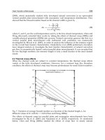
5. Fouling curves
The overall process of fouling is indicated by the fouling factor, R
f
(fouling resistance) which
is measured either by a test section or evaluated from the decreased capacity of an operating
heat exchanger. The representation of various modes of fouling with reference to time is
known as a fouling curve (fouling factor-time curve). Typical fouling curves are shown in
Fig. (3).
Fig. 3. Fouling Curves
The delay time,
t
d
indicates that an initial period of time can elapse where no fouling occurs.
The value of
t
d
is not predictable, but for a given surface and system, it appears to be
somewhat random in nature or having a normal distribution about some mean value or at
least dependent upon some frequency factors. After clean the fouled surfaces and reused
them, the delay time,
t
d
is usually shorter than that of the new surfaces when are used for
the first time. It must be noted that, the nature of fouling factor-time curve is not a function
of
t
d
. The most important fouling curves are:
- Linear fouling curve is indicative of either a constant deposition rate,
Ȃ
d
with removal
rate,
Ȃ
r
being negligible (i.e. Ȃ
d
= constant, Ȃ
r
§ 0) or the difference between Ȃ
d
and Ȃ
r
Linear
Falling
t
c
Asymptotic
Ȃ
d
= Ȃ
r
R
f
*
R
f
Time, t
t
d
t
*
512
Heat Transfer - Theoretical Analysis, Experimental Investigations and Industrial Systems
Fouling of Heat Transfer Surfaces
515
is constant (i.e.
Ȃ
d
– Ȃ
r
= constant). In this mode, the mass of deposits increases
gradually with time and it has a straight line relationship of the form (
R
f
= at) where “a“
is the slope of the line.
- Falling rate fouling curve results from either decreasing deposition rate,
Ȃ
d
with
removal rate,
Ȃ
r
being constant or decreasing deposition rate, Ȃ
d
and increasing
removal rate,
Ȃ
r
. In this mode, the mass of deposit increases with time but not linearly
and does not reach the steady state of asymptotic value.
- Asymptotic fouling curve is indicative of a constant deposition rate, Ȃ
d
and the removal
rate,
Ȃ
r
being directly proportional to the deposit thickness until Ȃ
d
= Ȃ
r
at the
asymptote. In this mode, the rate of fouling gradually falls with time, so that eventually
a steady state is reached when there is no net increase of deposition on the surface and
there is a possibility of continued operation of the equipments without additional
fouling. In practical industrial situations, the asymptote may be reached and the
asymptotic fouling factor,
R
*
f
is obtained in a matter of minutes or it may take weeks or
months to occur depending on the operating conditions. The general equation
describing this behavior is given in equation (4). This mode is the most important one in
which it is widely existed in the industrial applications. The pure particulate fouling is
one of this type.
For all fouling modes, the amount of material deposited per unit area,
m
f
is related to the
fouling resistance (R
f
), the density of the foulant (ǒ
f
), the thermal conductivity (nj
f
) and the
thickness of the deposit (
x
f
) by the following equation:
ffffff
mx R
U
UO
(2)
where
f
f
f
x
R
O
(3)
(values of thermal conductivities for some foulants are given in table 1).
Foulant
Thermal conductivity
(W/mK)
Alumina
Biofilm (effectively water)
Carbon
Calcium sulphate
Calcium carbonate
Magnesium carbonate
Titanium oxide
Wax
0.42
0.6
1.6
0.74
2.19
0.43
8.0
0.24
Table 1. Thermal conductivities of some foulants [2]
It should be noted that, the curves represented in Fig. (3) are ideal ones while in the
industrial situations, ideality may not be achieved. A closer representation of asymptotic
fouling practical curve might be as shown in Fig. (4). The “saw tooth” effect is the result of
partial removal of some deposit due to “spalling” or “sloughing” to be followed for a short
513
Fouling of Heat Transfer Surfaces
Heat Transfer - Theoretical Analysis, Experimental Investigations and Industrial Systems
516
time by a rapid build up of deposit. The average curve (represented by the dashed line) can
be seen to represent the ideal asymptotic curve on Fig. (3). Similar effects of partial removal
and deposition may be experienced with the other types of foulin curves.
Fig. 4. Practical fouling curve
6. Cost of fouling
Fouling affects both capital and operating costs of heat exchangers. The extra surface area
required due to fouling in the design of heat exchangers, can be quite substantial. Attempts
have been made to make estimates of the overall costs of fouling in terms of particular
processes or in particular countries. Reliable knowledge of fouling economics is important
when evaluating the cost efficiency of various mitigation strategies. The total fouling-related
costs can be broken down into four main areas:
4. Higher capital expenditures for oversized plants which includes excess surface area (10-
50%), costs for extra space, increased transport and installation costs.
5. Energy losses due to the decrease in thermal efficiency and increase in the pressure
drop.
6. Production losses during planned and unplanned plant shutdowns for fouling cleaning.
7. Maintenance including cleaning of heat transfer equipment and use of antifoulants.
The loss of heat transfer efficiency usually means that somewhere else in the system,
additional energy is required to make up for the short fall. The increased pressure drop
through a heat exchanger represents an increase in the pumping energy required to
maintain the same flow rate. The fouling resistance used in any design brings about 50%
increase in the surface area over that required if there is no fouling. The need for additional
maintenance as a result of fouling may be manifested in different ways. In general, any
extensive fouling means that the heat exchanger will have to be cleaned on a regular basis to
restore the loss of its heat transfer capacity. According to Pritchard [4], the total heat
exchanger fouling costs for highly industrialized countries are about 0.25% of the countries'
Gross National Product (GNP). Table (2) shows the annual costs of fouling in some different
countries based on 1992 estimation.
Fouling resistance, ( R
f
)
t
d
Time, (t)
514
Heat Transfer - Theoretical Analysis, Experimental Investigations and Industrial Systems
Fouling of Heat Transfer Surfaces
517
Country
Fouling Costs
(million $)
Fouling Cost /GNP
%
US 14175 0.25
UK 2500 0.25
Germany 4875 0.25
France 2400 0.25
Japan 10000 0.25
Australia 463 0.15
New Zealand 64.5 0.15
Table 2. Annual costs of fouling in some countries (1992 estimation) [5].
From this table, it is clear that fouling costs are substantial and any reduction in these costs
would be a welcome contribution to profitability and competitiveness. The frequency of
cleaning will of course depend upon the severity of the fouling problem and may range
between one weak and one year or longer. Frequent cleaning involving repeated
dismantling and reassembly will inevitably result in damage to the heat exchanger at a
lesser or greater degree, which could shorten the useful life of the equipment. Fouling can be
very costly in refinery and petrochemical plants since it increases fuel usage, results in
interrupted operation and production losses, and increases maintenance costs.
Increased Capital Investment
In order to make allowance for potential fouling the area for a given heat transfer surface is
larger than for clean conditions. To accommodate the fouling-related drop in heat transfer
capacity, the tubular exchangers are generally designed with 20-50% excess surface, where
the compact heat exchangers are designed with 15-25% excess surface. In addition to the
actual size of the heat exchanger other increased capital costs are likely. For instance where
it is anticipated that a particular heat exchanger is likely to suffer severe or difficult fouling,
provision for off-line cleaning will be required. The location of the heat exchanger for easy
access for cleaning may require additional pipe work and larger pumps compared with a
similar heat exchanger operating with little or no fouling placed at a more convenient
location. Furthermore if the problem of fouling is thought to be excessive it might be
necessary to install a standby exchanger, with all the associated pipe work foundations and
supports, so that one heat exchanger can be operated while the other is being cleaned and
serviced.
Under these circumstances the additional capital cost is likely to more than double and with
allowances for heavy deposits the final cost could be 4 - 8 times the cost of the
corresponding exchanger running in a clean condition. Additional capital costs may be
considered for on-line cleaning such as the Taprogge system (see sec. 12) or other systems. It
has to be said however, that on-line cleaning can be very effective and that the additional
capital cost can often be justified in terms of reduced operating costs. Furthermore the way
in which the additional area is accommodated, can affect the rate of fouling. For instance if
the additional area results say, in reduced velocities, the fouling rate may be higher than
anticipated and the value of the additional area may be largely offset by the effects of heavy
deposits. The indiscriminate use of excess surface area for instance, can lead to high capital
costs, especially where exotic and expensive materials of construction are required.
515
Fouling of Heat Transfer Surfaces
Heat Transfer - Theoretical Analysis, Experimental Investigations and Industrial Systems
518
Additional Operating Costs
The presence of fouling on the surface of heat exchangers decreases the ability of the unit to
transfer heat. Due to this decrement in the exchanger thermal capacity, neither the hot
stream nor the cold stream will approach its target temperature. To compensate this
shortage in the heat flow, either additional cooling utility or additional heating utility is
required. On the other hand, the presence of deposits on the surface of heat exchangers
increases the pressure drop and to recover this increment, an additional pumping work is
required and hence a greater pumping cost. Also the fouling may be the cause of additional
maintenance costs. The more obvious result of course, is the need to clean the heat
exchanger to return it to efficient operation. Not only will this involve labour costs but it
may require large quantities of cleaning chemicals and there may be effluent problems to be
overcome that add to the cost. If the cleaning agents are hazardous or toxic, elaborate safety
precautions with attendant costs, may be required.
The frequent need to dismantle and clean a heat exchanger can affect the continued integrity
of the equipment, i.e. components in shell and tube exchangers such as baffles and tubes
may be damaged or the gaskets and plates in plate heat exchangers may become faulty. The
damage may also aggravate the fouling problem by causing restrictions to flow and
upsetting the required temperature distribution.
Loss of Production
The need to restore flow and heat exchanger efficiency will necessitate cleaning. On a
planned basis the interruptions to production may be minimized but even so if the
remainder of the plant is operating correctly then this will constitute a loss of output that, if
the remainder of the equipment is running to capacity still represents a loss of profit and a
reduced contribution to the overall costs of the particular site. The consequences of enforced
shutdown due to the effects of fouling are of course much more expensive in terms of
output. Much depends on recognition of the potential fouling at the design stage so that a
proper allowance is made to accommodate a satisfactory cleaning cycle. When the
seriousness of a fouling problem goes unrecognized during design then unscheduled or
even emergency shutdown, may be necessary. Production time lost through the need to
clean a heat exchanger can never be recovered and it could in certain situations, mean the
difference between profit and loss.
The Cost of Remedial Action
If the fouling problem cannot be relieved by the use of additives it may be necessary to
make modifications to the plant. Modification to allow on-line cleaning of a heat exchanger
can represent a considerable capital investment. Before capital can be committed in this way,
some assessment of the effectiveness of the modification must be made. In some examples of
severe fouling problems the decision is straightforward, and a pay back time of less than a
year could be anticipated. In other examples the decision is more complex and the financial
risks involved in making the modification will have to be addressed. A number of
contributions to the cost of fouling have been identified, however some of the costs will
remain hidden. Although the cost of cleaning and loss of production may be recognized and
properly assessed, some of the associated costs may not be attributed directly to the fouling
problem. For instance the cost of additional maintenance of ancillary equipment such as
pumps and pipework, will usually be lost in the overall maintenance charges.
516
Heat Transfer - Theoretical Analysis, Experimental Investigations and Industrial Systems
Fouling of Heat Transfer Surfaces
519
7. Parameters affecting fouling
The fouling process is a dynamic and unsteady one in which many operational and design
variables have been identified as having most pronounced and well defined effects on
fouling. These variables are reviewed in principle to clarify the fouling problems and
because the designer has an influence on their modification. Those parameters include the
fluid flow velocity, the fluid properties, the surface temperature, the surface geometry, the
surface material, the surface roughness, the suspended particles concentration and
properties, …….etc. According to many investigators, the most important parameters are:
1. Fluid flow velocity
The flow velocity has a strong effect on the fouling rate where it has direct effects on both of
the deposition and removal rates through the hydrodynamic effects such as the eddies and
shear stress at the surface. On the other hand, the flow velocity has indirect effects on
deposit strength (Ǚ), the mass transfer coefficient (k
m
), and the stickability (P). It is well
established that, increasing the flow velocity tends to increase the thermal performance of
the exchanger and decrease the fouling rate. Uniform and constant flow of process fluids
past the heat transfer surface favors less fouling. Foulants suspended in the process fluids
will deposit in low-velocity regions, particularly where the velocity changes quickly, as in
heat exchanger water boxes and on the shell side. Higher shear stress promotes dislodging
of deposits from surfaces. Maintain relatively uniform velocities across the heat exchanger
to reduce the incidence of sedimentation and accumulation of deposits.
2. Surface temperature
The effect of surface temperature on the fouling rate has been mentioned in several studies.
These studies indicated that the role of surface temperature is not well defined. The
literatures show that, "increase surface temperature may increase, decrease, or has no effect
on the fouling rates". This variation in behavior does indicate the importance to improve our
understanding about the effect of surface temperature on the fouling process,
A good practical rule to follow is to expect more fouling as the temperature rises. This is due
to a “baking on” effect, scaling tendencies, increased corrosion rate, faster reactions, crystal
formation and polymerization, and loss in activity by some antifoulants [6]. Lower
temperatures produce slower fouling buildup, and usually deposits that are easily
removable [7]. However, for some process fluids, low surface temperature promotes
crystallization and solidification fouling. To overcome these problems, there is an optimum
surface temperature which better to use for each situation. For cooling water with a potential
to scaling, the desired maximum surface temperature is about 60°C. Biological fouling is a
strong function of temperature. At higher temperatures, chemical and enzyme reactions
proceed at a higher rate with a consequent increase in cell growth rate [8]. According to
Mukherjee [8], for any biological organism, there is a temperature below which
reproduction and growth rate are arrested and a temperature above which the organism
becomes damaged or killed. If, however, the temperature rises to an even higher level, some
heat sensitive cells may die.
3. Surface material
The selection of surface material is significant to deal with corrosion fouling. Carbon steel is
corrosive but least expensive. Copper exhibits biocidal effects in water. However, its use is
limited in certain applications: (1) Copper is attacked by biological organisms including
517
Fouling of Heat Transfer Surfaces
Heat Transfer - Theoretical Analysis, Experimental Investigations and Industrial Systems
520
sulfate-reducing bacteria; this increases fouling. (2) Copper alloys are prohibited in high-
pressure steam power plant heat exchangers, since the corrosion deposits of copper alloys
are transported and deposited in high-pressure steam generators and subsequently block
the turbine blades. (3) Environmental protection limits the use of copper in river, lake, and
ocean waters, since copper is poisonous to aquatic life. Noncorrosive materials such as
titanium and nickel will prevent corrosion, but they are expensive and have no biocidal
effects. Glass, graphite, and teflon tubes often resist fouling and/or improve cleaning but
they have low thermal conductivity. Although the construction material is more important
to resist fouling, surface treatment by plastics, vitreous enamel, glass, and some polymers
will minimize the accumulation of deposits.
4. Surface Roughness
The surface roughness is supposed to have the following effects: (1) The provision of
“nucleation sites” that encourage the laying down of the initial deposits. (2) The creation of
turbulence effects within the flowing fluid and, probably, instabilities in the viscous
sublayer. Better surface finish has been shown to influence the delay of fouling and ease
cleaning. Similarly, non-wetting surfaces delay fouling. Rough surfaces encourage
particulate deposition and provide a good chance for deposit sticking. After the initiation of
fouling, the persistence of the roughness effects will be more a function of the deposit itself.
Even smooth surfaces may become rough in due course due to scale formation, formation of
corrosion products, or erosion.
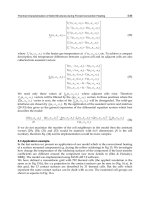
5. Fluid Properties
The fluid propensity for fouling is depending on its properties such as viscosity and density.
The viscosity is playing an important rule for the sublayer thickness where the deposition
process is taking place. On the other side the viscosity and density have a strong effect on
the sheer stress which is the key element in the removal process.
Fig. 5. Effect of the flow fluid type on the fouling
To show the effect of the flow fluid type on the fouling resistance, Chenoweth [7} collected
data from over 700 shell and-tube heat exchangers. These data of combined shell- and tube-
side fouling resistances (by summing each side entry), have been compiled and divided into
nine combinations of liquid, two-phase, and gas on each fluid side regardless of the
applications. The arithmetic average of total
R
f
of each two-fluid combination value has been
taken and analyzed. The results are presented in Fig. (5) with ordinate ranges between 0 and
518
Heat Transfer - Theoretical Analysis, Experimental Investigations and Industrial Systems
Fouling of Heat Transfer Surfaces
521
1.0. From this figure, it is clear that the maximum value is 1.0, that is due to liquid-liquid
heat exchanger, where the minimum value is 0.5 which belong to gas-gas heat exchanger. If
liquid is on the shell side and gas on the tube side, the relative fouling resistance is 0.65.
However, if liquid is on the tube side and gas on the shell side, it is 0.75. Since many process
industry applications deal with liquids that are dirtier than gases, the general practice is to
specify larger fouling resistances for liquids compared to those for the gases. Also, if fouling
is anticipated on the liquid side of a liquid–gas exchanger, it is generally placed in the tubes
for cleaning purposes spite a larger fouling resistance is specified. These trends are clear
from the figure. It should again be emphasized that Fig. (5) indicates the current practice
and has no scientific basis. Specification of larger fouling resistances for liquids (which have
higher heat transfer coefficients than those of gases) has even more impact on the surface
area requirement for liquid–liquid exchangers than for gas–gas exchangers.
6. Impurities and Suspended Solids
Seldom are fluids pure. Intrusion of minute amounts of impurities can initiate or
substantially increase fouling. They can either deposit as a fouling layer or acts as catalysts
to the fouling processes [6]. For example, chemical reaction fouling or polymerization of
refinery hydrocarbon streams is due to oxygen ingress and/or trace elements such as Va
and Mo. In crystallization fouling, the presence of small particles of impurities may initiate
the deposition process by seeding. The properties of the impurities form the basis of many
antifoulant chemicals. Sometimes impurities such as sand or other suspended particles in
cooling water may have a scouring action, which will reduce or remove deposits [9].
Suspended solids promote particulate fouling by sedimentation or settling under gravitation
onto the heat transfer surfaces. Since particulate fouling is velocity dependent, prevention is
achieved if stagnant areas are avoided. For water, high velocities (above 1 m/s) help prevent
particulate fouling. Often it is economical to install an upstream filtration.
7. Heat Transfer Process
The fouling resistances for the same fluid can be considerably different depending upon
whether heat is being transferred through sensible heating or cooling, boiling, or
condensing.
8. Design Considerations
Equipment design can contribute to increase or decrease fouling. Heat exchanger tubes that
extend beyond tube sheet, for example, can cause rapid fouling. Some fouling aspects must
be considered through out the equipment design such as:
1. Placing the More Fouling Fluid on the Tube Side
As a general guideline, the fouling fluid is preferably placed on the tube side for ease of
cleaning. Also, there is less probability for low-velocity or stagnant regions on the tube side.
2. Shell-Side Flow Velocities
Velocities are generally lower on the shell side than on the tube side, less uniform
throughout the bundle, and limited by flow-induced vibration. Zero-or low-velocity regions
on the shell side serve as ideal locations for the accumulation of foulants. If fouling is
expected on the shell side, then attention should be paid to the selection of baffle design.
Segmental baffles have the tendency for poor flow distribution if spacing or baffle cut ratio
is not in correct proportions. Too low or too high a ratio results in an unfavorable flow
regime that favors fouling.
519
Fouling of Heat Transfer Surfaces
Heat Transfer - Theoretical Analysis, Experimental Investigations and Industrial Systems
522
3. Low-Finned Tube Heat Exchanger
There is a general apprehension that low Reynolds number flow heat exchangers with low-
finned tubes will be more susceptible to fouling than plain tubes. Fouling is of little concern
for finned surfaces operating with moderately clean gases. Fin type does not affect the
fouling rate, but the fouling pattern is affected for waste heat recovery exchangers. Plain and
serrated fin modules with identical densities and heights have the same fouling thickness
increases in the same period of time.
4. Gasketed Plate Heat Exchangers
High turbulence, absence of stagnant areas, uniform fluid flow, and the smooth plate surface
reduce fouling and the need for frequent cleaning. Hence the fouling factors required in plate
heat exchangers are normally 10-25% of those used in shell and tube heat exchangers.
5. Spiral Plate Exchangers
High turbulence and scrubbing action minimize fouling on the spiral plate exchanger. This
permits the use of low fouling factors.
6. Seasonal temperature changes
When cooling tower water is used as coolant, considerations are to be given for winter
conditions where the ambient temperature may be near zero or below zero on the Celsius
scale. The increased temperature driving force during the cold season contributes to more
substantial overdesign and hence over performance problems, unless a control mechanism
has been instituted to vary the water/air flow rate as per the ambient temperature. Also the
bulk temperature of the cooling water that used in power condensers is changed seasonally.
This change influences the fouling rate to some extent.
8. Fouling measurements and monitoring
The fouling resistances can be measured either experimentally or analytically. The main
measuring methods include;
1-Direct weighing; the simplest method for assessing the extent of deposition on test surfaces
in the laboratory is by direct weighing. The method requires an accurate balance so that
relatively small changes in deposit mass may be detected. It may be necessary to use thin
walled tube to reduce the tare mass so as to increase the accuracy of the method.
2-Thickness measurement; In many examples of fouling the thickness of the deposit is
relatively small, perhaps less than
50 Ǎm, so that direct measurement is not easy to obtain. A
relatively simple technique provided there is reasonable access to the deposit, is to measure
the thickness. Using a removable coupon or plate the thickness of a hard deposit such as a
scale, may be made by the use of a micrometer or travelling microscope. For a deformable
deposit containing a large proportion of water, e.g. a biofilm it is possible to use an electrical
conductivity technique
3-Heat transfer measurements; In this method, the fouling resistance can be determined from
the changes in heat transfer during the deposition process. The basis for subsequent
operations will be Equation (14). The data may be reported in terms of changes in overall
heat transfer coefficient. A major assumption in this method is that the presence of the
deposit does not affect the hydrodynamics of the flowing fluid. However, in the first stages
of deposition, the surface of the deposit is usually rougher than the metal surface so that the
turbulence within the fluid is greater than when it is flowing over a smooth surface. As a
result the fouling resistance calculated from the data will be lower than if the increased level
of turbulence had been taken into account. It is possible that the increased turbulence offsets
520
Heat Transfer - Theoretical Analysis, Experimental Investigations and Industrial Systems
Fouling of Heat Transfer Surfaces
523
the thermal resistance of the deposit and negative values of thermal resistance will be
calculated.
4-Pressure drop; As an alternative to direct heat transfer measurements it is possible to use
changes in pressure drop brought about by the presence of the deposit. The pressure drop is
increased for a given flow rate by virtue of the reduced flow area in the fouled condition
and the rough character of the deposit. The shape of the curve relating pressure drop with
time will in general, follow an asymptotic shape so that the time to reach the asymptotic
fouling resistance may be determined. The method is often combined with the direct
measurement of thickness of the deposit layer. Changes in friction factor may also be used
as an indication of fouling of a flow channel.
5-Other techniques for fouling assessment; In terms of their effect on heat exchanger
performance the measurement of heat transfer reduction or increase in pressure drop
provide a direct indication. The simple methods of measuring deposit thickness described
earlier are useful, but in general they require that the experiment is terminated so as to
provide access to the test sections. Ideally non-intrusive techniques would allow deposition
to continue while the experimental conditions are maintained without disturbance. Such
techniques include the use of radioactive tracers and optical methods. Laser techniques can
be used to investigate the accumulation and removal of deposits. Also, infra red systems are
used to investigate the development and removal of biofilms from tubular test sections.
Microscopic examination of deposits may provide some further evidence of the mechanisms
of fouling, but this is generally a "back up" system rather than to give quantitative data.
Gas-Side Fouling Measuring Devices
The gas-side fouling measuring devices can be classified into five groups: heat flux meters,
mass accumulation probes, optical devices, deposition probes, and acid condensation
probes. A heat flux meter uses the local heat transfer per unit area to monitor the fouling.
The decrease in heat flux as a function of time is thus a measure of the fouling buildup. A
mass accumulation device measures the fouling deposit under controlled conditions.
Optical measuring devices use optical method to determine the deposition rate. Deposition
probes are used to measure the deposit thickness. Acid condensation probes are used to
collect liquid acid that accumulates on a surface that is at a temperature below the acid dew
point of the gas stream.
Instruments for Monitoring of Fouling
Instruments have been developed to monitor conditions on a tube surface to indicate
accumulation of fouling deposits and, in some cases, to indicate the effect on heat exchanger
performance. The following is a summary of the different fouling monitors [10, 11]:
1. Removable sections of the fouled surface, which may be used for microscopic
examination, mass measurements, and chemical and biological analysis of the deposits.
2. Increase in pressure drop across the heat exchanger length. This method provides a
measure of fluid frictional resistance, which usually increases with buildup of fouling
deposits. This device is relatively inexpensive and is easy to operate.
3. Thermal resistance monitors, which are used to determine the effect of the deposit on
overall heat transfer resistance. The thermal method of monitoring has the advantage over
the others of giving directly information that is required for predicting or assessing heat
transfer performance.
521
Fouling of Heat Transfer Surfaces
Heat Transfer - Theoretical Analysis, Experimental Investigations and Industrial Systems
524
9. Performance data analysis
As mentioned above, fouling has many effects on the heat exchanger perfornance. It
decreases the exchanger thermal capacity and increases the pressure drop through the
exchanger as shown in Fig. (6). From the figure it is clear that the total thermal resistance to
heat transfer is decreased during the first stages of fouling due to the surface roughness
resulting from initial deposition. After that and with deposits building up, the thermal
resistace returns to increase again.
Fig. 6. Fouling effects on exchanger performance
In order to model and predict the industrial processes fouling problems it is first necessary
to understand what is happening and what are the causes and effects of fouling. To achieve
this, it is necessary to carefully examine and evaluate all the data and operating conditions
at various plants in order to understand what the variables which are effective on fouling
and what are the mechanisms of such phenomena. The objective of these efforts will be
always to minimize the fouling clean-up / remediation shut-down frequency of the plants
and to reduce the cost by making the minimum modification in the processes.
The possibility of whether the fouling material is a part of the feed to the system or it is a
product of reaction / aggregation / flocculation in the system must be clarified. The role of
various operating conditions in the system on fouling (pressures, temperatures,
compositions, flow rates, etc. and their variations) must be understood and quantified. Only
with appropriate modeling considering all the possible driving forces and mechanisms of
fouling one may be able to predict the nature of fouling in each case and develop mitigation
techniques to combat that.
The available fouling history data would be useful to test the packages which will be
developed. Considering the diversity of the data, care must be taken in their analysis for any
universality conclusions. However, in order to make comparisons between fouling data
from various plants and test the accuracy of the developed packages, it will be necessary to
acquire the compositions data of the feed in each plant as well as characteristics and
conditions of operations of the process system used in those plants. Only then one can test
the accuracy of the models developed and understand why in one case there is fouling and
no fouling in another case.
Empirical data for fouling resistances have been obtained over many decades by industry
since its first compilation by TEMA in 1941 for shell-and-tube heat exchangers. TEMA
fouling resistances [12] are supposed to be representative values, asymptotic values, or those
manifested just before cleaning to be performed.
522
Heat Transfer - Theoretical Analysis, Experimental Investigations and Industrial Systems
Fouling of Heat Transfer Surfaces
525
It should be reiterated that the recommended fouling resistances are believed to represent
typical fouling resistances for design. Consequently, sound engineering judgment has to be
made for each selection of fouling resistances, keeping in mind that actual values of fouling
resistances in any application can be either higher or lower than the resistances calculated.
Finally, it must be clear that fouling resistances, although recommended following the
empirical data and a sound model, are still constant, independent of time, while fouling is a
transient phenomenon. Hence, the value of R
f
selected represents a correct value only at one
specific time in the exchanger operation. Therefore, it needs to be emphasized that the tables
may not provide the applicable values for a particular design. They are only intended to
provide guidance when values from direct experience are unavailable. With the use of finite
fouling resistance, the overall U value is reduced, resulting in a larger surface area
requirement, larger flow area, and reduced flow velocity which inevitably results in
increased fouling. Thus, allowing more surface area for fouling in a clean exchanger may
accelerate fouling initially.
Typical fouling resistances are roughly 10 times lower in plate heat exchangers (PHEs) than
in shell-and-tube heat exchangers (TEMA values), (see Table 3).
Process Fluid
R
f
, (m
2
· K/kW)
PHEs TEMA
Soft water
Cooling tower water
Seawater
River water
Lube oil
Organic solvents
Steam (oil bearing)
0.018
0.044
0.026
0.044
0.053
0.018–0.053
0.009
0.18–0.35
0.18–0.35
0.18–0.35
0.35–0.53
0.36
0.36
0.18
Table 3. Liquid-Side Fouling Resistances for PHEs vs. TEMA Values (from Ref.13)
10. Fouling models
Fouling is usually considered to be the net result of two simultaneous processes: a deposition
process and a removal process. A schematic representation of fouling process is given in Fig.
(1). Mathematically, the net rate of fouling can be expressed as the difference between the
deposition and removal rates as given in equation (1). Many attempts have been made to
model the fouling process. One of the earliest models of fouling was that by Kern and Seaton
[14]. In this model, it was assumed that the rate of deposition mass,
m
ғ
d
, remained constant
with time
t but that the rate of removal mass, m
ғ
r
, was proportional to the accumulated mass,
m
f
, and therefore increased with time to approach m
ғ
d
asymptotically. Thus
Rate of accumulation = Rate of deposition – Rate of removal
dm
f
/dt = m
ғ
f
= m
ғ
d -
m
ғ
r
(4)
then integration of Eqn. (4) from the initial condition m
f
= 0 at t = 0 gives
*
(1 )
t
ff
mm e
E
(5)
523
Fouling of Heat Transfer Surfaces
Heat Transfer - Theoretical Analysis, Experimental Investigations and Industrial Systems
526
where
m
f*
is the asymptotic value of m
f
and ǃ = 1/t
c
. The time constant t
c
represents the
average residence time for an element of fouling material at the heat transfer surface.
Referring to Eqn. (2), Eqn. (5) can be expressed in terms of fouling resistance
R
f
at time t in
terms of the asymptotic value
R
*
f
by
*
(1 )
t
ff
RR e
E
(6)
It is obvious that the real solution would be to find expressions for R
*
f
and t
c
as a function of
variables affecting the fouling process.
The purpose of any fouling model is to assist the designer or indeed the operator of heat
exchangers, to make an assessment of the impact of fouling on heat exchanger performance
given certain operating conditions. Ideally a mathematical interpretation of Eqn. (6) would
provide the basis for such an assessment but the inclusion of an extensive set of conditions
into one mathematical model would be at best, difficult and even impossible.
Modeling efforts to produce a mathematical model for fouling process have been based on
the general material balance given in Eqn. (4) and centered on evaluating the functions
m
ғ
d
and
m
ғ
r
for specific fouling situations, some of these models are:
Watkinson Model:
Watkinson [15] reported the effect of fluid velocity on the asymptotic fouling resistance in
three cases as;
1. Calcium carbonate scaling (with constant surface temperature and constant
composition)
R
*
f
= 0.101/(v
1.33
· D
0.23
) (7)
2. Gas oil fouling (with constant heat flux)
R
*
f
= 0.55/v
2
(8)
3. Sand deposition from water (with constant heat flux)
R
*
f
= 0.015/v
1.2
(9)
where;
R
*
f
the asymptotic fouling resistance
v the fluid velocity
D the tube diameter
Taborek, et al. Model:
Taborek, et al [16] introduced a water characterization factor to the deposition term to
account for the effect of water quality. The deposition term, also involves two processes; (1)
Diffusion of the potential depositing substance to the surface and (2) Bonding at the surface.
They expressed the deposition rate in an arrhenius type equation as the following:
1
exp( )
n
dd
g
s
Ea
kP
RT
) :
(10)
where
524
Heat Transfer - Theoretical Analysis, Experimental Investigations and Industrial Systems
Fouling of Heat Transfer Surfaces
527
k
1
deposition constant
P
d
deposition probability factor related to velocity and "Stickiness" or adhesion
characteristics of the deposit,
n exponent
ƺ water characterization factor,
(-E
a
/R
g
T
s
) the Arrhenius reaction rate function,
E
a
the activation energy,
R
g
the universal gas constant,
T
s
the absolute surface temperature
In this model, the removal rate was postulated to be a function of shear stress, deposit
thickness and bonding strength of the deposit. The removal function was given as:
2
()
r
f
kx
W
\
) (11)
where;
k
2
removal constant
Ǖ the fluid shear stress exerted on the deposit surface
Ǚ the strength or toughness of the deposit layer
Substituting for the deposition rate (Eqn.10) and removal rate (Eqn.11) into material balance
Eqn. (1) and taking into account Eqn. (3), the resulting equation yields to;
2
/
/
1
2
(1 )
f
kt
Ea RgTs
n
f
d
f
f
f
x
kP e e
R
k
O
W\
WO
O
\
:
(12)
and
*
1
2
Ea
R
g
Ts
n
d
f
f
kP e
R
k
WO
\
:
,
2
1
f
c
k
t
OW
E
\
(13)
Knudsen Analysis [17]:
As it is known, the fouling process is complicated and dynamic. The fouling resistance is not
usually measured directly, but must be determined from the degradation of the overall heat
transfer coefficient. The fouling factor,
R
f
, could be expressed as;
11
f
f
c
R
UU
(14)
Experimental fouling data have been analyzed on the basis of the change in overall heat
transfer coefficient of the fouling test section as in equation (16). It is assumed that the
thermal hydraulic condition in the test section remains reasonably constant for the duration
of the fouling test. The model of Taborek et al. is used and the two parameters
R
*
f
and t
c
can
be determined for each fouling situation, where;
R
*
f
is the asymptotic fouling resistance contains all the factors that influence fouling.
525
Fouling of Heat Transfer Surfaces
Heat Transfer - Theoretical Analysis, Experimental Investigations and Industrial Systems
528
t
c
is the time constant of the fouling resistance exponential curve i.e. the time required
for the fouling resistance to reach 63% of its asymptotic value (i.e. t
c
§ 0.63t
*
, see Fig.
3), it depends on the shear stress, the deposit strength factor and the deposit
thermal conductivity as;
t
c
= Ǚ / Ǖ k
2
nj
f
(15)
From the deposition – removal model, which was first presented by Kern and Seaton [13]
(Eqn. 6) and from Eqn. (14), the overall heat transfer coefficient of the fouled surface.
U
f
,
may be given as;
1
c
f
c
f
U
U
UR
(16)
then
*
1
1
(1 )
f
t
tc
f
c
U
Re
U
(17)
In equation (17), if the two coefficients
R
*
f
and t
c
can be obtained accurately either
empirically or analytically, they will be useful for predicting the fouling factor which can be
used in practical heat exchanger design.
11. Fouling and heat exchanger design
The heat exchanger designer must consider the effect of fouling upon the exchanger
performance during the desired operational lifetime and make provision in his design for
sufficient extra capacity to insure that the exchanger will meet process specifications up to
shutdown for cleaning. The designer must also consider what suitable arrangements are
necessary to permit easy cleaning.
In choosing the fouling resistances to be used in a given heat exchanger, the designer has
three main sources:
1. Past experience of heat exchanger performance in the same or similar environments.
2. Results from portable test rigs.
3. TEMA values, which are overall values for a very limited number of environments
(table 4).
As it is known, the overall thermal resistance for a heat exchanger involves a series of
thermal resistances from the hot fluid to the cold fluid, including thermal resistances due to
fouling on both fluid sides, as shown in Fig. (7). Based on the inside heat transfer surface
area A
i
, the overall heat transfer coefficient is expressed as:
,,
11 1
() ( )
wi i
fi fo
ii wwo o
AA
RR
Uh A h A
G
O
(18)
In Eqn. (18), it is assumed that the wall thermal resistance is for a flat plate wall. This
equation can be rearranged and simplified as
526
Heat Transfer - Theoretical Analysis, Experimental Investigations and Industrial Systems
Fouling of Heat Transfer Surfaces
529
Fig. 7. Thermal resistances for clean and fouled tubes
,,
11 1 1 1
wi i i i
fi fo f w
ii owwooi woo
AA AA
Ai
RR RR
Uh A A hAh A hA
G
O
(19)
Note that
R
f
=R
f,i
+R
f,o
(A
i
/A
o
) represents the total fouling resistance, a sum of fouling
resistances on both sides of the heat transfer surface, as shown. It should again be reiterated
that the aforementioned reduction in the overall heat transfer coefficient due to fouling does
not take into consideration the transient nature of the fouling process.
The current practice is to assume a value for the fouling resistance on one or both fluid sides
as appropriate and to design a heat exchanger accordingly by providing extra surface area
for fouling, together with a cleaning strategy. The complexity in controlling a large number
of internal and external factors of a given process makes it very difficult to predict the
fouling growth as a function of time using deterministic (well-known) kinetic models.
A note of caution is warranted at this point. There is an ongoing discussion among scholars
and engineers from industry as to whether either fouling resistance or fouling rate concepts
should be used as the most appropriate tool in resolving design problems incurred by
fouling. One suggestion in resolving this dilemma would be that the design fouling-
resistance values used for sizing heat exchangers be based on fouling-rate data and
estimated cleaning-time intervals.
In current practice, based on application and need, the influence of fouling on exchanger
heat transfer performance can be evaluated in terms of either (1) required increased surface
area for the same
q and ƦT
m
, (2) required increased mean temperature difference for the
same
q and A, or (3) reduced heat transfer rate for the same A and ƦT
m
. For these
approaches, the expressions; A
f
/A
c
, ƦT
m,f
/ƦT
m,c
and q
f
/ q
c
may be determined. In the first
two cases, the heat transfer rate in a heat exchanger under clean and fouled conditions are
the same. Hence,
cc m
ff
m
q
UA T U A T ' ' (for constant ƦT
m
) (20)
Therefore,
f
c
c
f
A
U
A
U
(21)
Where, the subscript
c denotes a clean surface and f the fouled surface.
Foulin
g
la
y
ers
Heat transfer
surface
CLEAN TUBE FOULED TUBE
Hot stream
Hot stream
Cold stream
Cold stream
527
Fouling of Heat Transfer Surfaces
Heat Transfer - Theoretical Analysis, Experimental Investigations and Industrial Systems
530
It must be noted that, the first case of the above mentioned approaches is the design of an
exchanger where an allowance for fouling can be made at the design stage by increasing
surface area, while the other two cases are for an already designed exchanger in operation,
and the purpose is to determine the impact of fouling on exchanger performance.
According to Eqn. (19), the relationships between overall heat transfer coefficients (based on
tube outside surface area) and thermal resistances for clean and fouled conditions are
defined as follows. For a clean heat transfer surface,
,,
11 1
oo
w
co
f
wi
f
i
AA
R
Uh AhA
(22)
For a fouled heat transfer surface,
,,,,
11 1 1 1
oo oo
fw fw
f
o
f
wi
f
io
f
wici
AA AA
RR RR
Uh AhAh AhA
(23)
For the ideal conditions that,
h
o,f
= h
o,c
, h
i,f
= h
i,c
, A
i,f
= A
i,c
= A
i
and A
o,f
= A
o,c
= A
o
, the
difference between Eqns. (22) and (23) yields to Eqn. (14) which is
11
f
f
c
R
UU
(14)
Combining Eqns. (14) and (21), it gets
1
f
cf
c
A
UR
A
(24)
Similarly, when
q and A are the same and ƦT
m
is different for clean and fouled exchangers, it
has
,,cc mc
f
cm
f
q
UA T U A T ' ' (for constant A) (25)
Hence,
,
,
mf
c
mc
f
T
U
TU
'
'
(26)
Combining Eqns. (14) and (26), it gets
,
,
1
mf
cf
mc
T
UR
T
'
'
(27)
Finally, if one assumes that heat transfer area and mean temperature differences are fixed,
heat transfer rates for the same heat exchanger under fouled and clean conditions are given
by
q
f
= U
f
A ƦT
m
and q
c
= U
c
A ƦT
m
, respectively. Combining these two relationships with
Eqn. (14), it gets
528
Heat Transfer - Theoretical Analysis, Experimental Investigations and Industrial Systems
Fouling of Heat Transfer Surfaces
531
1
1
f
ccf
q
qUR
(28)
Alternatively, Eqn. (28) can be expressed as
1
c
cf
f
q
UR
q
(29)
It is important to be noted that, the right-hand sides of Eqns. (24), (27) and (29) are the same.
From this set of equations, it can be concluded that, the percentage increment in A and ƦT
m
and the percentage reduction in q due to the presence of fouling are increased by increasing U
c
and/or R
f
. For this reason and to mitigate and attenuate the effects of fouling, the heat
exchanger must be operated with low U
c
. That is completely contrary to the well postulated
conceptions in the field of heat exchangers design that mostly recommend using high values of
U
c
. As an example for this fact, in Eqn. (24), if R
f
is of order 4x10
-4
m
2
·K/W, and U
c
of order 1000
W/m
2
·K, then the excess surface area will be 40%, where this excess ratio will be reduced to
only 20% if the U
c
was 500 W/m
2
·K with the same R
f
. Therefore, the low overall heat transfer
coefficients have been used in some processes in which the fouling resistances are severe such
as petrochemical industries to avoid the fouling impact on the exchanger performance.
Another important factor which related to the fouling resistance is the cleanliness factor, CF
and is given as
1
1
f
ccf
U
CF
UUR
(30)
TEMA fouling resistance values [12] for water and other fluids are given in Table (4).
Fluid
Fouling
Resistance
(10
4
m
2
.K/W)
Fluid
Fouling
Resistance
(10
4
m
2
.K/W)
LIQUID WATER STREAMS
Artificial spray pond water
Boiler blowdown water
Brackish water
Closed-cycle condensate
Closed-loop treated water
Distilled water
Engine jacket water
River water
Seawater
Treated boiler feedwater
Treated cooling tower water
INDUSTRIAL LIQUID
STREAMS
Ammonia (oil bearing)
1.75–3.5
3.5–5.3
3.5–5.3
0.9–1.75
1.75
0.9–1.75
1.75
3.5–5.3
1.75–3.5
0.9
1.75–3.5
5.25
CHEMICAL PROCESS STREAMS
Acid gas
Natural gas
Solvent vapor
Stable overhead products
CRUDE OIL REFINERY
STREAMS
Temperature § 120°C
Temperature § 120–180°C
Temperature § 180–230°C
Temperature
> 230°C
PETROLEUM STREAMS
Lean oil
Liquefied petroleum gases
3.5–5.3
1.75–3.5
1.75
1.75
3.5–7
5.25–7
7–9
9–10.5
3.5
1.75–3
529
Fouling of Heat Transfer Surfaces
Heat Transfer - Theoretical Analysis, Experimental Investigations and Industrial Systems
532
Engine lube oil
Ethanol
Ethylene glycol
Hydraulic fluid
Industrial organic fluids
Methanol
Refrigerants
Transformer oil
No. 2 fuel oil
No. 6 fuel oil
CRACKING AND COKING
UNIT STREAMS
Bottom slurry oils
Heavy coker gas oil
Heavy cycle oil
Light coker gas oil
Light cycle oil
Light liquid products
Overhead vapors
LIGHT-END PROCESSING
STREAMS
Absorption oils
Alkylation trace acid streams
Overhead gas
Overhead liquid products
Overhead vapors
Reboiler streams
1.75
3.5
3.5
1.75
1.75–3.5
3.5
1.75
1.75
3.5
0.9
5.3
7–9
5.3–7
5.3–7
3.5–5.3
3.5
3.5
3.5–5.3
3.5
1.75
1.75
1.75
3–5.5
Natural gasolene
Rich oil
PROCESS LIQUID STREAMS
Bottom products
Caustic solutions
DEA solutions
DEG solutions
MEA solutions
TEG solutions
CRUDE AND VACUUM
LIQUIDS
Atmospheric tower bottoms
Gasolene
Heavy fuel oil
Heavy gas oil
Kerosene
Light distillates and gas oil
Naphtha
Vacuum tower bottoms
INDUSTRIAL GAS OR VAPOR
STREAMS
Ammonia
Carbon dioxide
Coal flue gas
Compressed air
Exhaust steam (oil bearing)
Natural gas flue gas
Refrigerant (oil bearing)
Steam (non-oil bearing)
1.75–3.5
1.75–3.5
1.75–3.5
3.5
3.5
3.5
3.5
3.5
12.3
3.5
5.3–12.3
5.3–9
3.5–5.3
3.5–5.3
3.5–5.3
17.6
1.75
3.5
17.5
1.75
2.6–
3.5
9
3.5
9
Table 4. TEMA fouling resistance values for water and other fluids [12]
12. Heat exchanger cleaning
In most applications, fouling is known to occur in spite of good design, effective operation,
and maintenance. Hence, heat exchangers and associated equipment must be cleaned to
restore the heat exchanger to efficient operation. The time between cleaning operations will
depend upon the severity of the fouling problem. In some instances, cleaning can be carried
out during periodical maintenance programs (say, twice yearly or annually) but in other
cases frequent cleaning will be required, perhaps as frequently as monthly or quarterly. For
example, locomotive radiators are air blown during their fortnightly schedules.
Cleaning Techniques [18-20]
In general, the techniques used to remove the foulants from the heat exchanger surfaces can
be broadly classified into two categories:
mechanical cleaning and chemical cleaning. The
cleaning process may be employed while the plant is still in operation, that is named,
on-
line cleaning, but in most situations it will be necessary to shutdown the plant to clean the
530
Heat Transfer - Theoretical Analysis, Experimental Investigations and Industrial Systems
Fouling of Heat Transfer Surfaces
533
heat exchangers, known as off-line cleaning. In some instances combinations of these
cleaning methods may be necessary. Each method of cleaning has advantages and
disadvantages with specific equipment types and materials of construction.
Deposit Analysis
Information about the composition of fouling deposits through deposit analysis is extremely
helpful to identify the source of the major foulants, to develop proper treatment, and as an
aid in developing a cleaning method for a fouling control program. The sample should
represent the most critical fouling area. For heat exchangers and boilers, this is the highest
heat transfer area. Many analytical techniques are used to characterize deposit analysis.
Typical methods include x-ray diffraction analysis, x-ray spectrometry, and optical emission
spectroscopy.
Selection of Appropriate Cleaning Method
Before attempting to clean a heat exchanger, the need should be carefully examined.
Consider the following factors for selecting a cleaning method:
-
Degree of fouling.
-
Nature of the foulant, known through deposit analysis.
-
The compatibility of the heat exchanger material and system components in contact
with the cleaning chemicals (in the case of chemical cleaning which associated with
pumping hot corrosives through temporary connections).
-
Regulations against environmental discharges.
-
Accessability of the surfaces for cleaning.
-
Cost factors.
-
Precautions to be taken while undertaking a cleaning operation.
These precautions are listed in TEMA [12] as:
1. Individual tubes should not be steam blown because this heats the tube and may result
in severe thermal strain and deformation of the tube, or loosening of the tube to tube
sheet joint.
2.
When mechanically cleaning a tube bundle, care should be exercised to avoid damaging
the tubes. Tubes should not be hammered with a metallic tool.
Off-Line Mechanical Cleaning
Techniques using mechanical means for the removal of deposits are common throughout
the industry. The various off-line mechanical cleaning methods are
1. Manual cleaning 5. Soot blowing
2. Jet cleaning 6. Thermal cleaning
3. Drilling and Roding of tubes 7. Turbining
4. Blasting
1.
Manual Cleaning
Where there is good access, as with a plate or spiral heat exchanger, or a removable tube
bundle, and the deposit is soft, hand scrubbing and washing may be employed, although
the labor costs are high.
2.
Jet Cleaning
Jet cleaning or hydraulic cleaning with high pressure water jets can be used mostly on external
surfaces where there is an easy accessability for passing the high pressure jet. Jet washing can
be used to clean foulants such as: (1) airborne contaminants of air-cooled exchangers at a
531
Fouling of Heat Transfer Surfaces
Heat Transfer - Theoretical Analysis, Experimental Investigations and Industrial Systems
534
pressure of 2-4 bar, (2) soft deposits, mud, loose rust, and biological growths in shell and tube
exchangers at a pressure of 40-120 bar, (3) heavy organic deposits, polymers, tars in condensers
and other heat exchangers at a pressure of 300-400 bar, and (4) scales on the tube side and fire
side of boilers, pre-heaters, and economizers at a pressure of 300-700 bar. This method consists
of directing powerful water jets at fouled surfaces through special guns or lances. A variety of
nozzles and tips is used to make most effective use of the hydraulic force. The effectiveness of
this cleaning procedure depends on accessibility, and care is needed in application to prevent
damage to the tubes and injury to the personnel. Similar to water jet cleaning, pneumatic
descaling is employed on the fire side of coal-fired boiler tubes.
3.
Drilling and Roding of Tubes
Drilling is employed for tightly plugged tubes and roding for lightly plugged tubes. Drilling
of tightly plugged tubes is known as bulleting. For removing deposits, good access is
required, and care is again required to prevent damage to the equipment. A typical example
is roding of radiator tubes plugged by solder bloom corrosion products.
4.
Blast Cleaning
Blast cleaning involves propelling suitable abrasive material at high velocity by a blast of air
or water (hydroblasting) to impinge on the fouled surface. Hydroblasting is seldom used to
clean tube bundles because the tubes are very thin. However, the technique is suitable to
descale and clean tube-sheet faces, shells, channel covers, bonnets, and return covers inside
and outside.
5.
Soot Blowing
Soot blowing is a technique employed for boiler plants, and the combustion or flue gas heat
exchangers of fired equipment. The removal of particles is achieved by the use of air or
steam blasts directed on the fin side. Water washing may also be used to remove
carbonaceous deposits from boiler plants.
A similar cleaning procedure is followed for air
blowing of radiators on the fin side during periodical schedule attention.
6.
Thermal Cleaning
Thermal cleaning involves steam cleaning, with or without chemicals. This method is also
known as hydrosteaming. It can be used to clean waxes and greases in condensers and other
heat exchangers.
7.
Turbining
Turbining is a tube-side cleaning method that uses air, steam, or water to send motor-driven
cutters, brushes, or knockers in order to remove deposits.
Merits and Demerits of Mechanical Cleaning
The merits of mechanical cleaning methods include simplicity and ease of operation, and
capability to clean even completely blocked tubes. However, the demerits of this method
may be due to the damage of the equipment, particularly tubes, it does not produce a
chemically clean surface and the use of high pressure water jet or air jet may cause injury
and/or accidents to personnel engaged in the cleaning operation hence the personnel are to
be well protected against injuries.
Chemical Cleaning
The usual practice is to resort to chemical cleaning of heat exchangers only when other
methods are not satisfactory. Chemical cleaning involves the use of chemicals to dissolve or
loosen deposits. The chemical cleaning methods are mostly off-line. Chemical cleaning
methods must take into account a number of factors such as:
532
Heat Transfer - Theoretical Analysis, Experimental Investigations and Industrial Systems
Fouling of Heat Transfer Surfaces
535
1. Compatibility of the system components with the chemical cleaning solutions. If
required, inhibitors are added to the cleaning solutions.
2.
Information relating to the deposit must be known beforehand.
3.
Chemical cleaning solvents must be assessed by a corrosion test before beginning
cleaning operation.
4.
Adequate protection of personnel employed in the cleaning of the equipment must be
provided.
5.
Chemical cleaning poses the real possibility of equipment damage from corrosion.
Precautions may be taken to reduce the corrosion rate to acceptable levels. On-line
corrosion monitoring during cleaning is necessary. Postcleaning inspection is extremely
important to check for corrosion damage due to cleaning solvents and to gauge the
cleaning effectiveness.
6.
Disposal of the spent solution.
Chemical Cleaning Solutions
Chemical cleaning solutions include mineral acids, organic acids, alkaline bases, complexing
agents, oxidizing agents, reducing agents, and organic solvents. Inhibitors and surfactant
are added to reduce corrosion and to improve cleaning efficiency. Common foulants and
cleaning solvents are given in Table (5) and common solvents and the compatible base
materials are given in Table (6)
.
Foulant Cleaning solvent
Iron oxides
Calcium and magnesium scale
Oils or light greases
Heavy organic deposits such as
tars, asphalts, polymers
Coke/carbonaceous deposits
Inhibited hydrofluoric acid, hydrochloric acid,
monoammoniated citric acid or sulfamic acid,
EDTA
Inhibited hydrochloric acid, citric acid, EDTA
Sodium hydroxide, trisodium phosphate with or
without detergents, water-oil emulsion
Chlorinated or aromatic solvents followed by a
thorough rinsing
Alkaline solutions of potassium permanganate
or steam air decoking
Table 5. Foulants and Common Solvents [2]
General Procedure for Chemical Cleaning
The majority of chemical cleaning procedures follow these steps:
1.
Flush to remove loose debris.
2.
Heating and circulation of water.
3.
Injection of cleaning chemical and inhibitor if necessary in the circulating water.
4.
After sufficient time, discharge cleaning solution and flush the system thoroughly.
5.
Passivate the metal surfaces.
6.
Flush to remove all traces of cleaning chemicals.
It is suggested that one employ qualified personnel or a qualified organization for cleaning
services.
533
Fouling of Heat Transfer Surfaces