Laser Pulse Phenomena and Applications Part 12 pot
Bạn đang xem bản rút gọn của tài liệu. Xem và tải ngay bản đầy đủ của tài liệu tại đây (3.4 MB, 30 trang )
Mechanisms of Nanoparticle Formation by Laser Ablation
321
The second mechanism is due to gas-phase collisions and evaporations. These processes are
similar to the phenomena taking places in aggregation sources (Briehl & Urbassek, 1999;
Haberland, 1994). The major advantage of short and ultra-short laser pulses for cluster
synthesis is the presence of the laser-ejected small molecules and clusters in the ablated
flow. As a result, the formation of diatomic molecules in three-body collisions, which
represents a “bottleneck” for cluster formation in common aggregation sources, is not
crucial for cluster synthesis by short laser ablation.
5. References
Albert, O.; Roger, S.; Glinec, Y.; Loulergue, J. C.; Etchepare, J.; Boulmer-Leborgne, C.;
Perriere, J. & Millon, E. (2003).
Appl. Phys. A: Mater Sci. Process, 76, 319
Amoruso, S. ; Bruzzese, R. ; Spinelli, N. ; Velotta, R. ; Vitello, M. & Wang, X. (2004).
Europhys.
Lett
. 67, 404
Amoruso, S.; Ausaniob, G. ; Bruzzese, R. ; Campana, C. & Wang, X (2007).
Appl. Surf. Sci.,
254(4), p.1012
Anisimov, S. I. (1968).
Zh. Eksp. Teor. Fiz. 54, 339 (Sov. Phys. JETP, 27, 182 (1968))
Arunachalam, V. ; Lucchese, R. R. & Marlaow, W. H. (1999).
Phy. Rev. E 60, p 2051
Bird, G. A. (1994).
Molecular Gas Dynamics and the Direct Simulation of Gas Flows, Clarendon,
Oxford.
Boldarev, A. S. ; Gasilov, V. A. ; Blasco, F. ; Stenz, C.; Dorchies, F.; Salin, F.; Faenov, A. Ya.;
Pikuz, T. A.; Magunov, A. I. & Skobelev, I. Yu (2001).
JETP Letters, 73, 514
Brady, J. W.; Doll, J. D. & Thompson, D. L. (1979).
J. Chem. Phys., 71, 2467
Briehl, B. & Urbassek, H. M. (1999).
J. Vac. Sci. Technol. A 17, 256
Bulgakov, A. V. ; Ozerov, I.; Marine, W. (2004).
Appl. Phys. A 79, 1591
Daw M. S. & Baskes, M. I (1984).
Phys. Rev. B, 29, p. 6443
Frenkel, D. & Smit, B. (1996).
Understanding molecular simulation, Academic Press
Garrison, B. J.; Itina, T. E. & Zhigilei, L. V. (2003).
Phys. Rev. E,68, 041501
Geohegan, D. B. ; Puretzky, A. A. ; Dusher, G. & Pennycook, S. J. (1998).
Appl. Phys. Lett., 72,
2987
Glover, T. E. (2003).
J. Opt. Soc. Am. B, 20, 125
Gusarov, A. V. ; Gnedovets, A. V. & Smurov, I. (2000).
J. Appl. Phys. 88, 4362
Haberland, H. (1994).
Clusters of Atoms and Molecules, ed. by H. Haberland (Springer, Berlin),
p. 205
Handschuh, M. ; Nettesheim, S. & Zenobi, R. (1999).
Appl. Surf. Sci., 137(1-4) p. 125–135
Hittema H. & McFeaters, J. S. (1996).
J. Chem. Phys. 105, 2816
Itina, T. E.; Tokarev, V. N.; Marine, W. & Autric, M. (1997).
J. Chem. Phys. 106, 8905
Itina, T.E.; Hermann, J. ; Delaporte, P. & Sentis, M. (2002).
Phys. Rev. E, 66, 066406
Jarold, M. F. (1994).
Clusters of Atoms and Molecules, ed. by H. Haberland (Springer, Berlin,),
p. 163.
Kinjo, T.; Ohguchi, K. ; Yasuoka, K. & Matsumoto, M. (1999).
Computational Materials Science,
14, 138-141
Luk’yanchuk, B. ; Marine, W. & Anisimov, S. (1998).
Laser Phys. 8, 291
Makimura, T. ; Kunii, Y. & Murakami, K. (1996).
Jpn. J. Appl. Phys. Part 1, 35, 4780
Malakhovskii, A. V. & Ben-Zion, M. (2001)
. Chem. Phys, 264, 135-143
Mizuseki, H. ; Jin, Y. ; Kawazoe, Y. & Wille, L. T. (2001).
Appl. Phys. A 73, 731
Laser Pulse Phenomena and Applications
322
Movtchan, I. ; Dreyfus, R. W. ; Marine, W. ; Sentis, M. ; Autric, M. & Le Lay, G. (1995). Thin
Solid Films
255, 286
Noël, S.; Hermann, J. (2009)
Applied Physics Letters, 94:053120
Ohkubo, T.; Kuwata, M. ; Luk’yanchuk, B. ; Yabe, T. (2003).
Appl. Phys. A., 77, 271
Perez, D. & Lewis, L. J. (2002).
Phys. Rev. Lett., 89, 25504
Schenter, G. K.; Kathmann, S. M. & Garett, B. C. (1999).
Phys. Rev. Letters, 82, 3484-3487
Vitiello, M.; Amoruso, S.; Altucci, C. ; de Lisio, C. & Wang, X. (2005).
Appl. Surf. Sci., 248(1-4),
p. 404
Yamada, Y.; Orii, T.; Umezu, I. ; Takeyama, S. & Yoshida
, Y. (1996). Jpn. J. Appl. Phys. Part 1,
35, 1361
Zeldovich, Y. B. & Raizer, Yu. P. (1966).
Physics of Shock Waves and High Temperature
Hydrodynamic Phenomena
Academic Press, London
Zeifman, M. I. ; Garrison, B. J. & Zhigilei, L. V. (2002).
J. Appl. Phys. 92, 2181
Zhigilei, L. V. ; Kodali, P. B. S. & Garrison, B. J. (1998).
J. Phys. Chem. B, 102, 2845-2853
Zhigilei, L. V. & Garrison, B. J. (2000).
J. Appl. Phys. 88, ( 3), 1281
Zhigilei, L. V. (2003).
Appl. Phys. A 76, 339
Zhong, J. ; Zeifman, M. I. & Levin, D. A. (2006).
J. Thermophysics and Heat Transfer, 20, 41-45
16
Ablation of 2-6 Compounds with
Low Power Pulses of YAG:Nd Laser
Maciej Oszwaldowski, Janusz Rzeszutek and Piotr Kuswik
Poznan University of Technology, Faculty of Technical Physics
Poland
1. Introduction
The 2-6 compounds and their mixed crystals are important semiconductor materials with
practical applications in various areas of solid state electronics and optoelectronics. Most of
the applications need these materials in a thin film form. One of the most versatile methods
of obtaining thin films and their composed structures is the Pulsed Laser Deposition (PLD)
method. That method has been used many times to the deposition of the 2-6 compound
films and the result of the investigations of both the target ablation process and the obtained
films physical properties were published in numerous publications. The earlier publications
have been summarized in several excellent reviews (Cheung & Sankur, 1988; Christley &
Hubler, 1994; Dubowski, 1991). In spite of the existing broad experimental material,
optimum technological conditions for obtaining 2-6 compound layers by PLD with pre-
defined properties has not as yet been determined. This is because the layers properties
depend on the Pulsed Laser Ablation (PLA) process of the target material. The ablation
depends on such parameters of the process as: the energy and duration of the laser pulse,
pulse repetition frequency and the angle of incidence, target preparation method and some
others. Therefore, the PLA is a multi-parameters process.
It has been recently shown (Rzeszutek et al., 2008a,b) that pulsed laser ablation of CdTe
target with low - power pulses of YAG:Nd laser can be an effective method for the
deposition of high quality CdTe thin films. The advantages of using low-power pulses of
YAG:Nd laser for the CdTe ablation are following. The YAG:Nd laser is as such a very
stable and environmentally harmless laser that can be very easy handled. Because the
thermal evaporation of CdTe results in nearly congruent vaporisation of Cd and Te
(Ignatowicz S. & A. Koblendza 1990), it may be expected that the low - power pulsed laser
ablation should be a very effective method of the deposition of CdTe thin films. However,
the most important reason that ablation is performed in the low-power regime, realized by
long pulse duration of 100 µs, is to minimize the splashing effect that is the effect of emitting
of macroscopic particularities from the target (Cheung & Sankur, 1988). That degrades the
quality of the thin films obtained by the laser ablation. Therefore, the type of the laser and its
pulse duration time are dictated by practical reasons.
In this chapter we summarize our earlier experiments on the ablation of CdTe and add new
results on the ablation of CdSe and ZnTe not as yet published. Like CdTe, these two latter
compounds, are rather volatile materials, and the use of the low-power YAG:Nd laser
ablation for their thin film preparation can be substantiated largely in the same way as it is
Laser Pulse Phenomena and Applications
324
done above for CdTe. Therefore, in the following we will present and discuss the results on
the PLA of a group of the 2-6 compounds, which allows on some generalization of the
conclusions.
However, our main goal is not the presentation of the physical properties of the 2-6 thin
films obtained in the low-power regime of the YAG:Nd PLA. It is rather the ablation process
itself and its dependence on the parameters of the process. Our main points of interest are:
the dependence of the ablation process of the 2-6 compounds on the target preparation
method and laser pulse energy and the effect of these factors on the velocity distribution of
emitted particles.
The chapter’s material is organized in the following way. In Sec. 2 the experimental
procedures are described. Here a general experimental set-up for performing PLA is given
together with the description of the Time-Of-Fly measurement method. Sec. 3 is devoted to
the dependence of the pulsed laser ablation of the 2-6 compounds on target preparation
method. In particular, the vapour stream intensity and the chemical composition and their
mutual evolution with time are investigated with the help of a quadrupole mass
spectrometer. These studies are performed for three kinds of targets: a target made of CdTe
bulk crystal (BC target), a target made of CdTe fine powder pressed under the pressure of
700 atms (PP target), and a target made of loose (non-pressed) CdTe powder (N-PP target).
Results obtained for PP targets made of CdSe and ZnTe are also presented. Sec. 4 deals with
the velocity distribution of emitted particles. It starts with a theoretical background and
continues with experimental velocity distribution of particles and comparison with the
theory. The velocity distribution is determined by the time-of-fly (TOF) spectrometry
performed by a quadrupole mass spectrometer. This section deals also with the angular
distribution of particles. In Sec. 5 final conclusions are drawn.
2. Experimental procedures
2.1 Apparatus for pulsed laser ablation of semiconductor materials
The pulsed laser ablation of the 2-6 materials has been performed in an apparatus for pulsed
laser deposition of semiconductor thin films described earlier (Oszwałdowski et al., 2003). A
general scheme of the main part of the apparatus is shown in Fig. 1. Important elements of
the apparatus are:
Laser. A typical neodymium doped yttrium–aluminum–garnet (YAG:Nd) laser is used. It
has the following parameters: wavelength ,1.064 µm; maximum pulse energy, 0.5 J;
instability of the pulse energy, 6%; pulse duration in the free generation mode, 100 µs; pulse
duration in the Q-switched mode, 10 ns; repetition time, 10–50 Hz; beam divergence, 3
mrad; and beam diameter, 7 mm.
In the further described experiments the Nd:YAG laser operates at 25 Hz or 35 Hz pulse
frequency. The pulse energy is changed from 0.13 J to 0.25 J; however most of the
experiments are performed with the energy of 0.16 J. The laser spot on the target has the
effective (roughly FWHM) diameter of 0.2 cm, thus the surface density of the energy is
changed from 4 J/cm
2
to 8 J/cm
2
, and the most frequently applied energy density is 5 J/cm
2
.
For the applied laser pulse duration of 100 µs, the pulse power is changed from 1.3·10
3
W to
2.5·10
3
W, and the most frequently applied power is 1.6·10
3
W. Therefore, the applied laser
pulse powers fall into the low power regime (Cheung &.Sankur, 1988; Christley &Hubler,
1994). The low pulse power and the relatively large laser spot are chosen to diminish the
splashing.
Ablation of 2-6 Compounds with Low Power Pulses of YAG:Nd Laser
325
Optical path of laser beam. The laser radiation beam falls onto a focusing mirror having the
focal length of 80 cm. This mirror is attached to a guide that enables to shift the mirror, and
thereby its focal point in relation to the targets plane. As a rule, in order to decrease the
radiation surface density power with the aim of avoiding splashing, the mirror focal plane is
shifted from the target plane. The extent of the off focusing depends on the target material.
Fig. 1. Sketch of the apparatus for PLD of semiconductor thin films.
1. YAG:Nd laser, 2. Computer controlled system of laser beam monitoring, 3. Device
switching laser beam between targets (optical deflector) , 4. Focusing mirror, 5. Quartz plate,
6. Photodiode system for measurement laser beam intensity, 7. Meter or oscilloscope, 8.
Optical port of laser beam, 9. Heater of internal optical port, 10. Substrate holder and heater,
11. targets, 12. Substrates, 13. Vacuum chamber, 14. QMS at first port, 15. Peep holes, 16.
Second QMS port.
The concave mirror reflects the beam onto a flat mirror of the optical deflector, which directs
the beam through an opening in the substrate holder/heater onto a surface of one of the
targets.
Other details of the apparatus construction less important for the present studies can be
found in the source article (Oszwałdowski et al., 2003 )
Quadrupol Mass Spectrometer (QMS) The apparatus is supplied with a quadrupole mass
spectrometer (QMS, HALO 301, Hiden Analytical) equipped with a pulse ion counter. The
action of the QMS is synchronized with the laser action by a specially designed electronic
device. With this improvement, the vapour cloud ejected from the target by a laser pulse
arrives at the spectrometer head in a proper time to be recorded and analysed on its
chemical composition. Determination of chemical composition of the vapour stream and the
velocity distribution of emitted particles are main functions of QMS in present
investigations.
2.2 Time-Of-Fly experiments
An important part of the present investigations is performed with Time-Of-Fly (TOF)
experiments. They are carried out with the use of the quadrupole mass spectrometer
Laser Pulse Phenomena and Applications
326
equipped with a pulse ion counter (PIC) as an ion detector. Here, the option of the
measurements of the delay times between the electric pulse triggering the laser shot and the
detection of the ionized particles by the ion detector is exploited for the determination of the
particle delay time distribution (Rzeszutek et al., 2008b). From that, the velocity distribution
of particles in the vapour stream is determined. The total particle delay time is composed of
the following partial delay times: the laser pulse generation time, the particle emission time,
the particle TOF between the target and the orifice of the ionizer, the particle arrival to PIC
time, the PIC reaction time (given by the manufacturer to be between 30 ns and 50 ns). The
time of the laser pulse generation is determined with the help of an electronic circuit
equipped with a photodiode as a radiation detector. The time of the laser pulse generation is
assumed to be the FWHM of the signal shown, which is about of 70 µs, and thus is close to
the value of the 100 µm given by the QMS manufacturer.
The sketch of the configuration applied in the measurement of TOF is shown in Fig. 2. The
TOFs are measured with the substrate heater, H removed from its position (10) in the
vacuum chamber shown in Fig. 1. The sum of the remaining delay times is determined from
the difference in the total delay times t
1
and t
2
, measured at two different distances l
1
= 43
cm and l
2
= 24 cm between the target and the ionizer entry. For this purpose, the particle
velocity v = (l
1
-l
2
)/(t
1
-t
2
) was determined in the first step. Then, from the knowledge of v, t
1
and t
2
the sum of the remaining delay times is determined to be 0.12 ms. In the subsequent
measurements, the TOFs were measured only for the distance l
1
and the TOF velocity was
determined from the equation:
11
/( 0.12)vl t=−, where t
1
is in milliseconds. The measured
values of
1
(0.12)t − were in the range from 0.4 to 4 ms, whereas the range of measurable
delay times was from 0.1 to 100 ms. Thus, the system was capable to measure the TOFs of all
particles that appeared at the ionizer.
Fig. 2. Sketch of configuration applied for TOF and angular distribution measurements. (D)
particle detector (PIC), (K) particle ionizer and quadrupole, (T) target, (L) laser beam, l
1
& l
2
distances between lower and upper position of target, respectively, (H) substrate heater,
removed from position for TOF measurements.
The target holder is a rotating copper cup having the inner diameter φ = 2 cm. The angular
velocity of the cup can be changed.
Ablation of 2-6 Compounds with Low Power Pulses of YAG:Nd Laser
327
2.3 Target preparation method
In the present experiments three types of targets are used: a target made of powdered
material poured directly into the holder cup (non-pressed powder target, N-PP target), a
pellet made of a fine powder pressed at a pressure of 700 atm (pressed powder target, PP
target), and a slice cut off from a CdTe bulk crystal (bulk crystal target, BC target). The
diameter of the targets made of the powder is 2 cm and the diameter of the bulk CdTe
crystal target is 1 cm. The ablation runs, lasting 9-14 minutes are performed at a constant
laser power. The quadrupole system of the QMS head is directed roughly towards the
target. The orifice of the head is lightly shifted parallel to the target surface in such a way
that the line joining the orifice centre with the target centre makes an angle of 19° with the
target normal. The distance between the orifice and the target surface is 43 cm. During the
ablation process the pressure in the vacuum chamber is about 10
-6
torr.
3. Pulsed laser ablation of 2-6 compounds: Dependence on target
preparation method
3.1 Dependence of vapour stream intensity on pulse
The study of the dependence of the vaporisation intensity of CdTe, CdSe and ZnTe on the
laser pulse energy is performed on the PP targets. The vapour stream intensity for each
compound is deduced from two different and independent measurements. In the first
measurement method total amount of the mass ablated by the action of 10000 laser pulses of
a given energy is measured by weighing the pellet before and after the ablation and
evaluating the difference. From these data the average mass ablated by a single pulse is
determined. In the second measurement method, the total number of counts is registered, by
the QMS, in the same ablation process for the isotope
110
Cd in the case of CdTe and CdSe
and the isotope
66
Zn in the case of ZnTe. From that, the average number of counts for a
single pulse is determined. Thus, in both measurements, a magnitude proportional to the
vapour stream density is determined. The measurement results for the laser pulse energies
ranging from 130 mJ to 250 mJ are shown in Fig. 3.
3,5 4,0 4,5 5,0 5,5 6,0 6,5 7,0 7,5
0,1
1
10
100
1000
0,1
1
10
100
1000
counts/pulse
Reciprocal of energy pulse [1/J]
Counts/pulse
mass/pulse
Mass/pulse [µg]
CdSe
3,5 4,0 4,5 5,0 5,5 6,0 6,5 7,0 7,5
0,1
1
10
100
1000
0,1
1
10
100
1000
Reciprocal of energy pulse [1/J]
Counts/pulse
counts/pulse
Mass
/
pulse [µg]
mass/pulse
ZnTe
3,5 4,0 4,5 5,0 5,5 6,0 6,5 7,0 7,5
0,1
1
10
100
1000
0,1
1
10
100
1000
- counts/pulse
Count/pulse
Reciprocal of energy pulse [1/J]
Mass/pulse [µg
]
- mass/pulse
CdTe
Fig. 3. Dependence of the vapour stream intensity from CdSe, ZnTe and CdTe PP targets on
the inverse of the laser pulse energy ranging from 130 mJ to 250 mJ. The left scale shows the
number of QMS counts per a single laser shot. The right scale shows the mass ablated by a
single laser shot
Laser Pulse Phenomena and Applications
328
It is seen in the figure that for both measurement methods, there is a good agreement as for
the character of the dependence of the vaporisation intensity on the pulse energy. This
dependence is linear in the scale logarithm of the vapour stream density versus the inverse
of the pulse energy. In the applied range of the energy density, the mass evaporated by a
single laser shot is between 0.6 µg and 8 µg for CdTe, and between 0.1 µg and 20 µg for CdSe
and ZnTe. Thus the effectiveness of evaporation for CdSe and ZnTe is higher.
The presented studies of the dependence of the vapour stream density on pulse energy for
the targets made of CdTe, CdSe and ZnTe are performed in the power density range (4-
8)*10
4
W/cm
2
that is for the densities smaller than 10
6
W/cm
2
, which is a region known as
the low power density range (Cheung & Sankur, 1988). In this range the particle emission is
expected to have the thermal character, in which the stream density S depends on the
thermal energy kT, acquired from the pulse energy E according to the relationship:
exp
H
S
kT
Δ
⎛⎞
∝−
⎜⎟
⎝⎠
(1)
where ΔH is the heat of vaporisation. Fig. 3 shows that the results for the PP targets comply
with Eq. (1) under the assumption that the kT is proportional to the pulse energy. However,
it should be pointed out that in the case of materials having a high vapour pressure, the
ablation with laser pulses in the low power density regime does not mean a low particle
stream density (Kelly & Miotello, 1994).
Since CdTe, CdSe and ZnTe show in Fig. 3 a linear dependence of the stream density on the
energy pulse reciprocal, it is possible to calculate the slopes of the curves. They should be
roughly proportional to the heats of vaporisation (enthalpies of sublimation). The
determined curve slopes for CdSe, ZnTe and CdTe respectively are: -1.33 µg J/pulse, -1.24
µg J/pulse and -0.78 µg J/pulse. The respective enthalpies of sublimation for CdSe, ZnTe
and CdTe are: 1.7 10
6
J/kg (Bardi et al., 1988), 1.6 10
6
J/kg (Nasar & Shamsuddin, 1990) and
1.2 10
6
J/kg (Bardi et al., 1988). Comparing the absolute values of the curve slopes with the
values of the enthalpies of sublimation, we find some correlation between them. Namely,
they decrease in the same order and the values for CdSe and ZnTe are very close, whereas
corresponding values for CdTe are distinctly smaller. The correspondence between the
curve slopes and the sublimation enthalpies seems to further confirm the thermal nature of
the ablation process.
Each change in the pulse energy has an effect on the surface appearance of the ablated area.
A similar effect has the degree of the spatial overlapping of two consecutive laser shots on
the target. The surface appearance of a PP target made of CdTe and ablated with laser shots
having the energy of 160 mJ is shown in Fig. 4. The shown in the figure detail is a fragment
of a 2 mm wide circular track carved by the laser beam on the target surface. The left-hand
side of the figure marked a) shows an area ablated with 20000 laser shots, of which spots did
not overlapped. After moving the laser spot along the target radius towards the target
centre and reducing the angular speed of the target to a half of its initial value, the
consecutive laser spots overlapped. The result of the ablation performed with overlapping
spots is shown on the right-hand side of the figure, marked b). The left- and the right-hand
side of the figure are separated by a narrow and smooth part of the target surface, marked c)
that was not laser ablated. It is seen in the figure that the laser ablation results in formation
of a surface structure consisting of granular forms. However, the topography of the part
Ablation of 2-6 Compounds with Low Power Pulses of YAG:Nd Laser
329
ablated with the overlapping spots is richer and shows higher roughness. The ablation with
overlapping spots increases local temperature of the ablated area formed by 2-3 consecutive
shots. This effect, called further overheating, is equivalent to the increase in the energy of
the laser pulse.
The effect of a genuine increase of the laser pulse energy is shown in Fig. 5.
Fig. 4. Surface appearance of CdTe PP target ablated with 160 mJ laser pulses (optical
microscope).
Part a) shows fragment of circular track ablated with 20000 non-overlapping laser shots.
Part b) shows fragment of circular track ablated with 20000 overlapping laser shots. Both
parts are separated by narrow circular strip (c) of the material that was not laser ablated.
Fig. 5. Surface appearance of CdTe PP target ablated with 250 mJ laser pulses (optical
microscope). Surface structure is obtained after 30000 laser shots.
The observed fragment of the circular track is a result of the ablation with non-overlapping
shots, 30000 in number, with the pulse energy of 250 mJ. Comparing Fig. 4 and Fig. 5, it can
be seen that the increase in the shot energy leads to a more developed surface structure
showing considerably higher roughness. This is quite a general observation for all studied
materials, as may be concluded from Fig. 6 that shows the results for CdSe and ZnTe PP
targets.
Laser Pulse Phenomena and Applications
330
Fig. 6. Surface morphology of CdSe and ZnTe PP targets after ablation with laser pulse
energy: 130 mJ, a) and 250 mJ, b).
It is clearly seen that the fragments of the targets ablated with the 130 mJ pulses is much
smoother that the fragments ablated with the 250 mJ pulses. In Figs 4, 5, and 6 one can
observe than at the higher pulse energy (250 mJ) the formation of characteristic conical
forms occurs in the ablated material. This formation can be associated with the granular
nature of the PP targets.
3.2 Vapour chemical composition and its time dependence
In order to perform the stream intensity measurements with QMS, it is necessary to choose a
proper isotope of each element of the compounds. The number of isotopes of Cd, Zn, Se and
Te respectively is: 8, 5, 6 and 7. For the monatomic species we have chosen the following
isotopes:
110
Cd,
66
Zn,
78
Se, and
128
Te. For the diatomic species we have chosen:
256
Te
2
resulting from the sum (pairing) of the monatomic species:
128
Te +
128
Te and
126
Te +
130
Te.
For
156
Se
2
we have chosen resulting from the sum of the monatomic species:
78
Se +
78
Se,
76
Se
+
80
Se,
74
Se +
83
Se. This choice of the masses is an optimum from the point of view of the
measurement convenience. With this choice, the QMS signals from all the chosen masses
have comparable amplitudes. That enables their convenient observation on the screen in the
same signal scale.
In the case of CdTe, all three forms of the target are investigated. Prior to the investigations
of the vapour streams generated by the laser, we studied the vaporisation of CdTe powder
by the normal thermal vaporisation from a heated quartz crucible. We were particularly
interested in the ratio of the vapour streams of the monatomic and the diatomic forms,
J(Te)/J(Te
2
). In the investigations we have found that at relatively slow thermal vaporisation
of CdTe powder, the ratio of the QMS signals from the masses 128 and 256 is 0.25 and shows
tendency to increase to about 0.5 at a fast vaporisation. Hence, taking into account the
species abundances we obtained that purely thermal evaporation of CdTe gives at least a 20
% participation of monatomic Te in the stream.
The investigations of the chemical composition of the vapour stream generated by the laser
pulses are performed both with overlapping and non-overlapping laser shots. The ablations
are carried out with 160 mJ pulses and the frequency of 35 Hz. A typical ablation time is 9
Ablation of 2-6 Compounds with Low Power Pulses of YAG:Nd Laser
331
minutes, and that corresponds to 20000 laser pulses. Results obtained for the BC target are
shown in Fig. 7. Results obtained for non-overlapping spots are shown in the left-hand side
panels, and those for overlapping laser shots are shown in the right-hand side panels. The
panels a1 and a2 show the time dependence of the QMS signals from the
110
Cd and the
128
Te
isotopes as well as for the
256
Te
2
molecules.
It should be noted that the particle emission starts with some delay, which amounts to about
one minute, counting from the beginning of the ablation. Such a delay for the start of the
ablation was also observed in earlier works for various target materials. In the case of CdTe
it was explained by the existence of an energy threshold for the ablation. The existence of the
threshold was explained with a complicated mechanism, in which a two-phonon
mechanism is employed at the initial stage to heat-up the material to the level sufficient for
the generation of numerous structural defects and a decrease in the energy gap that enable
much more effective single-phonon absorption in the final stage (Dubowski, 1991). At that
moment the target material shows very high absorption for the laser radiation.
Comparing the dependences shown in the panels a1 and a2, it is seen that the stream
intensity at the beginning of the ablation is higher for the ablation with overlapping spots,
but it decreases considerably with time. No such a decrease is observed for the non-
overlapping spots. The higher stream intensity observed for the ablation with the
overlapping spots is clearly due to the higher local temperature at the spot area that results
from a cumulative heat effect of the overlapping laser shots. This is an outcome of the poor
heat conductivity of CdTe.
It may be seen in the panels a1 and a2 of Fig, 7 that the time dependence of the stream
intensity for all masses has the same character, except for the first two minutes. This means
that after the first two minutes the masses are emitted from the target congruently.
To make it more clear, we determine the time dependence of the relative signal intensities
S(
110
Cd)/S(
256
Te
2
) and S(
110
Cd)/S(
128
Te) from the data shown in the panels a1 and a2. The
results are shown in the panels b and c respectively. It is seen that if the first two minutes
are skipped, the signal ratios do not show any clearly marked dependence on time. That
means that the total vapour stream has stoichiometric composition corresponding to the
CdTe compound. It is also observed in Fig. 7 that the signal ratio S(
128
Te)/S(
256
Te
2
) increases
with time during the first two minutes from the value of about 1.5 to the value of about 2.5,
and then tends to saturate at this value. Taking into account the particle abundances
(Rzeszutek et. al., 2008a), it results that the total particle stream ratio J(Te)/J(Te
2
) increases
from 1.2 to 2.0. The latter value is by about an order of magnitude higher than the 0.25
obtained for the pure thermal evaporation. Therefore, in the case of the bulk crystal target
and the ablation without the laser spot overlapping, the vapour stream contains twice more
monatomic Te particles than diatomic Te
2
particles. This is quite different from the case of
the same target, but ablated with the laser spot overlapping. As seen in the panel b2, in that
case the signal ratio S(
128
Te)/S(
256
Te
2
) = 0.5, and it is constant from the beginning of the
ablation. The value 0.5 corresponds to the particle stream ratio J(Te)/J(Te
2
) amounting to
0.41 and, as mentioned earlier, this is also the value characteristic for a fast thermal
evaporation at high temperatures.
The panels c1 and c2 of Fig. 7 show that the signal ratio S(
110
Cd)/S(
128
Te) decreases during
the first two minutes of the ablation, and then saturates. It is clear that in the case of the non-
overlapping laser shots, this initial decrease is in fact due to a relatively smaller participation
Laser Pulse Phenomena and Applications
332
Fig. 7. Time dependence of QMS signals obtained during laser ablation of CdTe BC target.
Left panels show dependence for non-overlapping laser shots, and right panels show
dependence for overlapping laser shots. Panels a1 and a2 show time dependence of QMS
signals from Cd, Te and Te
2
. Symbols S(
128
Te)/S(
256
Te
2
) or S(
110
Cd)/S(
128
Te) in remaining
panels mean ratio of signals S from Te and Te
2
or from Cd and Te respectively. Ablation is
performed with laser frequency of 35 Hz and pulse energy of 160 mJ.
of the monatomic Te species in comparison with the diatomic Te
2
species in the total
tellurium stream (panel b1). The time dependence of the ratio S(
110
Cd)/S(
256
Te
2
) (not shown)
does not reveal any such a decrease. On contrary, in the case of the overlapping laser shots,
that initial decrease, as may be concluded from the panel b2, cannot be associated with any
change in the participation of the monatomic Te species in the total tellurium stream. Thus,
the initial decrease is associated with an initial excess of cadmium in the vapour stream.
Investigations of the ablation process of the PP targets are performed in the way analogous
to those described for the bulk CdTe target. These investigations reveal that at the same
ablation conditions the erosion of the target made of pressed power is considerably larger
than that of the BC target. Since the initial smoothness of both types of the targets was
similar, this may confirm that the much larger roughness of the pressed powder target is
associated with its granular character. The investigation results for the CdTe PP targets are
shown in Fig. 8.
0246810
0
300
600
900
1200
1500
1800
QMS
s
i
gna
l
S
[C
oun
t
s
]
Te
Te
2
Time [min]
Cd
a1
0246810
0,0
0,5
1,0
1,5
2,0
2,5
3,0
3
,
5
S(
128
Te)
/
S(
2
56
Te
2
)
Time
[
mi n
]
b1
0246810
0
1
2
3
4
5
6
S(
110
Cd)/ S(
128
Te)
Time [min]
c1
0246810
0
300
600
900
1200
1500
1800
QMS
s
i
gna
l
S
[C
oun
t
s
]
Te
Time [min]
Cd
Te
2
a2
0246810
0,0
0,5
1,0
1,5
2,0
2,5
3
,
0
S(
128
Te)/S(
2
56
Te
2
)
Time [min]
b2
0246810
0
1
2
3
4
5
6
S(
110
Cd)/ S(
128
Te)
Time [min]
c2
Ablation of 2-6 Compounds with Low Power Pulses of YAG:Nd Laser
333
Fig. 8. Time dependence of QMS signal obtained during laser ablation of CdTe PP target.
Left panels show dependence for non-overlapping laser spots, and right panels show
dependence for overlapping laser spots. Panels a1 and a2 show time dependence of QMS
signals from Cd, Te and Te
2
Symbols S(
128
Te)/S(
256
Te
2
) or S(
110
Cd)/S(
128
Te) in remaining
panels, mean ratio of signals S from Te and Te
2
or from Cd and Te respectively. Ablation is
performed with laser frequency of 35 Hz and pulse energy of 160 mJ.
It is seen in the panels a1 and a2 that in contrast to the BC target, in the present case the
particle emission process commences immediately after the start of the laser action. This
means that the powdered CdTe has sufficiently large number of structural defect to be
strongly absorbent for the laser radiation. In the case of the non-overlapping laser spots, the
magnitude of the QMS signal is slightly lower at the ablation beginning, as compared to the
signal magnitude from the bulk crystal CdTe target, and further decreases with time. On the
other hand, in the case of the overlapping laser spots, the magnitude of the QMS signal is
comparable with that from the bulk crystal CdTe target at the ablation beginning, but its
further decrease with time is stronger. Comparing the results for the overlapping and non-
overlapping spots in the panels a1 and a2 of Fig.8, it is seen that the signal decrease is
distinctly stronger in the case of the overlapping spots. In contrast to the ablation of the bulk
crystal CdTe target, in the present case during the first 1-2 minutes of the intense particle
emission, sporadic splashing is observed. Approximately after that time, a crust is formed
0246810
0
200
400
600
800
1000
QMS signal S [Counts]
Te
Te
2
Time
[
min
]
Cd
a1
0246810
0,0
0,5
1,0
1,5
2,0
2,5
3
,
0
S(
128
Te)/S(
256
Te
2
)
Time [min]
b1
0246810
0
1
2
3
4
5
6
S(
110
Cd)/ S(
128
Te)
Time [min]
c1
0246810
0
300
600
900
1200
1500
QMS signal S [Counts]
Cd
Te
2
Te
Time [min]
a2
0246810
0,0
0,5
1,0
1,5
2,0
2,5
3
,
0
S(
128
Te)/S(
2
56
Te
2
)
Time
[
min
]
b2
0246810
0
1
2
3
4
5
6
S(
110
Cd)/ S(
128
Te)
Time
[
min
]
c2
Laser Pulse Phenomena and Applications
334
on the ablated surface of the target. The crust is located in a groove formed by the laser
action. At that time, the target surface becomes increasingly rough. The crust is expected to
be formed in the process of melting and subsequent freezing of the powder.
Panels b1 and b2 in Fig. 8 show the ratio of the signals for the masses 128 and 256. During
the first 1-2 minutes this ratio is roughly constant, and next it increases with the ablation
time from the value of 1 to about 1.7. These values correspond to the vapour stream ratio
J(Te)/J(Te
2
) from 0.82 to 1.4. The signal ratio S(
110
Cd)/S(
128
Te) slightly decreases during the
first three minutes of the ablation, and then slightly increases with time. This behaviour is
more clearly seen in the case of the overlapping laser spots (panel c2). The increase with
time and simultaneous increase in the S(
128
Te)/S(
256
Te
2
) ratio can be understood under the
assumption that in addition to the direct laser ablation, there is also a contribution from
purely thermal evaporation of the target material associated with its local overheating
resulting from the low thermal conductivity of the pressed powder. In such a case, one
could expect the thermal evaporation component would show an excess of cadmium. This
assumption is supported by the fact that the increase in the ratio S(
110
Cd)/S(
128
Te) is more
pronounced in the case of the overlapping laser shots, which cause a larger overheating.
The characteristic features of the ablation process of the N-PP target can be presented by a
comparison of the experimental results obtained for the N-PP target with those obtained for
the BC and the PP targets. In the case of the N-PP target, the signal magnitudes both for the
ablation with and without overlapping of the laser shots are markedly higher than those for
the PP target, and also higher than those for the BC target. During the ablation of an N-PP
target splashing is observed and that is particularly intense during the first 1-2 minutes.
Moreover, during the ablation, a glowing tail is formed and it follows the laser spot in its
travel around the moving target. The glowing part of the target has to be the source of
purely thermal evaporation of the target material. Like in the case of the BC and PP targets,
the ablation with overlapping laser shots is more effective. In comparison with the PP target,
the decrease with time of the stream intensity is markedly smaller, and resembles that
occurring for the bulk crystal target, however, with the exception that the particle emission
starts immediately after the laser action onset. The composition of the tellurium vapour stream
is dominated by the thermal evaporation from the glowing spot (Rzeszutek et al., 2008a).
As in the case of the PP target, the laser ablation leads to the formation of a crust on the top
of the ablated powder. The ablated surface roughness of the N-PP target is considerably
higher than that of the PP target. Also the laser carved groove is considerably deeper.
The investigations of the chemical composition of the vapour stream for ZnTe and CdSe are
performed on pressed powder targets. The ablations are carried out with 25 Hz pulses in
time of 9 minutes that corresponds to about 10000 laser pulses. The pulse energy is 250 mJ
for CdSe, and 220 mJ for ZnTe. Results obtained for ZnTe are shown in the left-hand side
panels, and those for CdSe are shown in the right-hand side panels of Fig. 9.
Panel a1 shows the time dependence of the QMS signals from
66
Zn and
128
Te isotopes as well
as from
256
Te
2
molecules. On the other side, panel a2 shows the time dependence of the QMS
signals from
110
Cd and
78
Se isotopes and from
156
Se
2
molecules. It may be observed in both
panels that at an initial stage of the ablation, the signal intensity increases. This may be
associated with gradual heating up the target by the laser action. If this is the case,
comparison of Figs. 7 and 9 leads to the conclusion that the heating up is much faster for
CdTe than that for ZnTe. The reason for that is unknown.
Ablation of 2-6 Compounds with Low Power Pulses of YAG:Nd Laser
335
02468
0
2000
4000
6000
8000
10000
Zn
Te
QMS signal S [Counts]
Time [min]
Te
2
a1
02468
0.0
0.5
1.0
1.5
2.0
2.5
3.0
S
(Te
128
)/S
(Te
256
)
Time [min]
b1
02468
2
3
4
5
6
7
8
9
10
S
(Zn
66
)/S
(Te
128
)
Time [min]
c1
02468
0
2000
4000
6000
8000
10000
12000
Se
QMS signal S [Counts]
Time [min]
Se
2
Cd
a2
02468
0
1
2
3
4
5
6
7
S
(Cd
110
)/S
(Se
78
)
Time [min]
c2
02468
0,0
0,5
1,0
1,5
2,0
2,5
3,0
S
(Se
78
)/S
(Se
156
)
Time [min]
b2
Fig. 9. Time dependence of QMS signal obtained during laser ablation of PP targets made of
ZnTe, left panels and CdSe, right panels. Panel a1 shows time dependence of QMS signals
from Cd, Te and Te
2
,
and panel a2 shows time dependence of QMS signals from Cd, Se and
Se
2
. In remaining panels are shown ratios of signals S from various particle streams.
Ablations are performed with laser non-overlapping spots, frequency of 25 Hz and pulse
energy of 220 mJ, for ZnTe, and 250 mJ, for CdTe.
Panels a1 and a2 show also that time dependences of the signals from all masses are more or
less the same. A more precise investigation of this observation can be done by the
determination of the ratios of signals from various masses. This is done in further panels.
Panel b1 shows the time dependence of the ratio of the signals from the masses 128 and 256,
and panel b2 shows the time dependence of the ratio of the signals from the masses 156 and
78. As it is seen, with the exception for the initial stage of the ablation, both ratios are time
independent in the first approximation. It is interesting that the signal ratio S(
128
Te)/S(
256
Te)
is close to unity and weakly time dependent both for ZnTe and CdTe (Fig. 7). Thus the
signal ratio is weakly dependent of the chemical composition.
Panel c1 shows the time dependence of the ratio of the signals from the masses 66 and 128.
The ratio is time independent in the first approximation.
Laser Pulse Phenomena and Applications
336
Panel c2 shows the time dependence of the ratio of the signals from the masses 110 and 78.
This ratio decrease with time. That may be the result of the increase with time of the stream
of the mass 78 observed in panel b2.
The observed dependence of the particle emission magnitude for CdTe, CdSe and ZnTe on
the target properties can in a large part be explained with the difference in the target heat
conductance. For example, the fact that the stream intensity emitted from the N-PP target is
higher than the intensities found for BC and PP targets at the same ablation conditions can
be explained by the poor heat conductance of the N-PP target that leads to a local
temperature increase, and finally results in a more intensive particle emission.
It is observed that for all targets, the intensity of the stream of the emitted particles is
initially higher for the overlapping spots, but the intensity strongly decreases with time, and
after first 3-4 minutes the intensity decreases below the level observed for the non-
overlapping spots. The higher initial vapour stream intensity in the case of the overlapping
spots can also be explained in terms of the local temperature increase. However, the strong
decrease in the vapour intensity with time needs additional explanation. First of all, it is
observed that the decrease in the vapour intensity is strictly correlated with the increase in
the surface roughness. The latter is expected to result in a decrease in the angular
dependence of the emitted particles. It is known that the laser ablation of a flat and smooth
target surface leads to a very directional particle emission. Preferred is the “forward
emission”, i.e. emission in the direction normal to the surface. In the case of a rough surface
the local forward emission can be directed quite differently than the direction of the normal
to the target surface as a whole. Thus, it is expected that emission from a rough target will
be much less directional than that from a smooth target. In such a case the number of
particles reaching the QMS detector, of which the angular position is close to the target
normal, will strongly decrease with the increase in the surface roughness. Therefore, it is
possible that the observed decrease in the measured by QMS stream intensity is associated
with the structural changes (roughness) of the target surface resulting in changes in the
stream angular dependence, rather than reflects any real changes in the total stream
intensity.
Cheung in his PLA studies of CdTe (Cheung, 1987) found that the stream intensity ratio
J(Te)/J(Te
2
) strongly increases with the laser pulse power. In some qualitative agreement
with that, we find that in the case of the typical thermal evaporation, this ratio increases
with temperature, from a value of about 0.2 to a value of about 0.4, and ratios J(Te)/J(Te
2
higher than 0.5 can be reached in the typical laser ablation only. Therefore, one can assume
that the increase in the ratio J(Te)/J(Te
2
) is a measure of a departure from the purely thermal
evaporation to the typical laser ablation. In the result, one can conclude that the most typical
in character pulsed laser ablation has the ablation of the BC target with no spatial
overlapping of the consecutive laser shots. The steady increase in the J(Te)/J(Te
2
) ratio with
time to the final value of 2.0 suggests that in a later time the target temperature still
increases, which is equivalent to an increase in the laser pulse power. The same thermal
effects can be responsible for the increase with time of the J(Te)/J(Te
2
) ratios for the
remaining targets. The very low J(Te)/J(Te
2
) ratio in the case of the bulk crystal target
ablated with overlapping shots can be related to a considerably larger spot overlapping
(larger than in the case of the powder targets) resulting from the smaller diameter of that
target. Due to the local overheating of the target, the particle emission has the chemical
composition that is closer to a pure thermal evaporation than to a typical laser ablation.
Ablation of 2-6 Compounds with Low Power Pulses of YAG:Nd Laser
337
3.3 Dependence on target preparation method: Summary and conclusions
The main goal of this Section is to explain the effect of the target preparation method on the
ablation process. The basic investigation method is the determination of the vapour stream
intensity and chemical composition, as well as their real time evolution with the help of a
quadrupole mass spectrometer synchronized with the laser action. The studies are
performed for three kinds of targets made of CdTe, CdSe and ZnTe. Such investigations are
carried out for the first time. They revealed that the ablation has a thermal character; i. e. the
process is thermally activated through an energy barrier (Kelly & Miotello, 1994). In spite of
the fact that he ablation process is performed in the low power regime, it is very effective
because of the high volatility of the 2-6 compounds. The thermal ablation is concluded on
the basis of Fig. 3, which shows that for all compounds the stream density is proportional to
the pulse energy reciprocal. Hence, the experimental results can be described by the
relationship of Eq. (1), if one assumed that the thermal energy kT is gained from the laser
pulse energy.
It may be observed in Fig. 3 that for CdSe and ZnTe the evaporated masses per pulse are
comparable, and for CdTe they are smaller. Nevertheless, for the pulse energy of 1/6 J (=166
mJ) the emitted mass is about 1 µg/pulse for all the compounds. This means that a target
prepared from a homogeneous mixture of powders of these compounds should under the
laser ablation emit the vapour of chemical composition corresponding to the target average
composition. Thus homogeneous thin films of mixed crystals of the compounds could be
obtained.
In the PLA experiments, the target erosion is large and is characterized by a considerable
surface roughness, especially in the case of the powder targets. The surface roughness
increases with the laser pulse power and frequency and also with the degree of spatial
overlapping of subsequent laser pulse spots on the target surface. With the development of
the roughness the ablation effectiveness decreases. It seems that the apparent decrease in the
particle emission is connected with a change in the angular distribution of the emitted
particles introduced by the roughness. The less forward directed particle emission from the
target, confirmed further on by the studies of the stream angular distribution, could be
important for the practical application of PLD as a thin film deposition method because the
typical very directional particle evaporation is a drawback of PLD.
In the present experiments, large surface roughness is as a rule formed in the conditions of
target overheating, which results in an enhanced target vaporisation. In this case the vapour
stream consists of a component typical for the true laser vaporisation and a component
typical for the thermal vaporisation associated with the target overheating. These two
components can be distinguished in the investigations of the ratio of the number of the
monatomic VI group particles (VI = Te or Se) to the number of the diatomic particles VI
2
(Te
2
., Se
2
). In the case of CdTe, the stream ratio J(Te)/J(Te
2
) < 0.5 is typical for pure thermal
vaporisation and the J(Te)/J(Te
2
) > 0.5 is typical for true laser ablation. The highest value of
the ratio is found during the ablation of the CdTe BC target without any spot overlapping.
Only in this case the vapour stream has the stoichiometric composition (Cd/Te = 1) from the
beginning of the ablation. In the other ablation processes, the vapour stream has some
excess of Cd during the first minutes of the ablation. This period can be prolonged in the
ablation of the powder targets with the spot overlapping. These effects are understood in
terms of the differences in the thermal conductivity between the targets.
The obtained experimental results can be a basis of a comparison of the targets from the
point of view of their practical value. The most useful chemical composition of the vapour
Laser Pulse Phenomena and Applications
338
stream in the low power regime can be obtained with the target made of a slice of a
crystalline 2-6 compound ablated with well specially separated subsequent laser shots. The
stream composition is in this case stoichiometric from the beginning and has a high particle
ratio J(VI)/J(VI
2
). The latter is advantageous for obtaining high quality epitaxial films of the
2-6 compounds (Cheung, 1987). A substantial drawback of that target, when ablated with
the Nd:YAG laser, is the energetic threshold for the ablation and the (irregular) delay in the
ablation process above the threshold.
On contrary, the main advantage of the powder targets over the BC target is the lack of any
ablation threshold or delay. Also the costs of preparation of the powder targets are
substantially lower. However, the smaller effective heat conductance of these targets poses
the problem of the target overheating even in a more demanding form. To avoid the
generation of the thermal component of the vapour stream, the subsequent laser shots
should be well spatially separated. In addition to this, the laser frequency and/or improved
heat sink may have to be applied. The target prepared from the compressed powder is a
reasonable choice for the pulsed laser deposition of thin films of the 2-6 compounds,
provided that the initial ablation, in which the more intense splashing and the non-
stoichiometric composition of the vapour take place, is eliminated. This can be done by the
use of a typical shutter that is a standard equipment of most vacuum evaporation plants.
The N-PP target is the simplest form of the target that can be prepared instantly. The main
advantage of that target is that due to the very low thermal conductivity, it can be ablated
effectively with very small laser powers. However, owing to the splashing, the large thermal
component, and the non-stoichiometry of the vapour stream, its applicability to the pulsed
laser deposition of the thin films of the II-VI compounds is rather limited to some
preliminary deposition tests.
4. Pulsed laser ablation of 2-6 compounds: Velocity distribution of emitted
particles
In this section we continue the investigation of the ablation process through the
determination of the emitted particle velocity and angle distribution. The velocity
distribution is determined by the time-of-fly spectrometry. It is known that the TOF
spectrometry is a very useful characterisation method of the PLA process; however, the
interpretation of results obtained needs a lot of care (Kelly & Miotello, 1994).
The information on the distribution of particle velocities during the laser ablation of the 2-6
compounds is rather limited. The PLA of CdTe was performed by Cheung (Cheung, 1987).
He used 100 µm pulses of a Nd:YAG laser and found that the particle velocity distribution is
the full Maxwell-Boltzmann. Namiki et al. (Namiki et al., 1986) also observed the full M-B
distribution of particles for CdS. However, as shown further on, our velocity distributions
obtained from the TOF studies are much narrower than the classic M-B distribution, which
means that ablation takes place in the condition of the formation of the Knudsen layer (KL)
followed by adiabatic expansion (KL-AE). These studies are carried out for all three types of
targets and from them the velocities of the stream and the most probable velocities in the
centre-of-mass system are determined.
The formation of KL-AE leads to a specific angular distribution of the emitted particles,
which is strongly forward directed. The investigation of those distributions for the three
types of the target is also the subject of our studies.
Ablation of 2-6 Compounds with Low Power Pulses of YAG:Nd Laser
339
4.1 Theoretical velocity distribution
The laser ablation process, in particular PLA, of various solid state materials both organic
and inorganic, liquids and suspensions is a point of interest for many researchers working in
a wide variety of scientific domains. This diversity may be the reason of the existing
confusion on the nomenclature, definitions and assumptions encountered in the literature
devoted to the physical description of the gas (plasma) generated in vacuum by laser pulses.
In this connection, it seems appropriate to introduce the definitions and formulae that are
used in the presentation and interpretation of the experimental results presented in the
further part of this contribution.
The velocity distribution of a perfect gas at temperature, T is described by the Maxwell-
Boltzmann distribution function
()
2
2
2
0
exp
v
fv v
v
⎛⎞
∝−
⎜⎟
⎜⎟
⎝⎠
(2)
where v is the particle velocity and
2/
o
vkTm= , (3)
is the most probable particle velocity in the gas. In Eq. (3), T is the gas temperature, and m is
the particles mass. In the Cartesian coordinate system, in which the gas mass centre is
resting,
2222
x
y
z
vvvv=++, and , ,
xyz
vvv
−
∞< <+∞. The same functional form has the velocity
distribution of particles emitted during the thermal ablation of a target, provided that the
particle concentration is sufficiently small for the emission process to be collisionless (Kools
et al., 1992; Anisimov, 1968). If the target normal is directed along the z-axis, the movement
along this direction is limited by the condition, v
z
> 0, which means that the centre-of-mass
of the particle stream drives away from the target surface. Therefore, the gas is described by
the distribution defined by Eq. (2) with v
z
> 0. This so-called “half-range” M-B distribution
can be the basis of the interpretation of the TOF measurements, provided that the following
measurement conditions are fulfilled (Kelly & Dreyfus, 1988):
a.
Both the detector sensitive area and the emission area are small in comparison with the
distance between them,
b.
The detector is on-axis, i.e., the detector area and the emission area are parallel and
have a common normal,
c.
The particle emission time is much smaller than TOF.
The specific geometry of TOF measurements causes the TOF distribution is different from
that given by Eq. (2) by a pre-exponential factor v
n
. In the case of the TOF distribution we
have
()
2
4
TOF
2
0
exp
v
fvv
v
⎛⎞
∝−
⎜⎟
⎜⎟
⎝⎠
. (4)
It should be mentioned that this form of the TOF distribution function with n = 4 applies to
the particle detector sensitive to particle concentration. This is the case when a QMS is
applied (Kelly & Dreyfus, 1988). The v in Eq. (4) is the velocity measured within a small
solid angle around the target surface normal, i. e.,
z
vv
≅
.
Laser Pulse Phenomena and Applications
340
It is sometimes argued that the pre-exponential factor in Eq. (4) should be v
3
(Kools et al.,
1992) instead of v
4
. We are, however, more convinced by the arguments given by Kelly
(Kelly, 1992) for the pre-exponential factor v
4
, and will thus use it in the following. However,
in view of the dominant role of the exponential term, the difference between those two pre-
exponential factors does not have any meaningful effect on the general interpretation of the
presented experimental results.
Particle emission with collisions is accompanied by the formation of the Knudsen layer at
the target surface, where the collisions occur. In such a case, Eq. (2), with the condition, v
z
>
0, applies at the closest vicinity of the target surface only. Moreover, owing to the collisions,
the gas cloud evolves to the distribution called shifted M-B or M-B on stream velocity. In this
distribution v
z
in Eq. (2) has to be replaced by (v
z
– u), where u is the so-called stream velocity
or centre-of mass-velocity. In the result, when the Knudsen layer is formed one obtains:
()
()
2
2
2
0
exp
vu
fv v
v
⎛⎞
−
⎜⎟
∝−
⎜⎟
⎝⎠
. (5)
It is important to note that, owing to collisions, for this distribution we have:
,,
xyz
vvv−∞ < < +∞ . For u = 0, we are in the COM system, and the distribution becomes the
classic M-B distribution of Eq. (2). Now, v
0
is the most probable velocity among the
velocities, v in the COM system, and Eq. (3) defines temperature in the COM system. In the
laboratory system, to the distribution described by Eq. (5) belongs the following most
probable velocity:
2
2
0, 0
22
r
uu
vv
⎛⎞
=+ +
⎜⎟
⎝⎠
. (6)
It is observed that for
0
uv>> , from Eq. (6) one obtains
0,r
vu
≅
.
With the formation of the Knudsen layer, Eq. (4) evolves to the form
()
()
2
4
TOF
2
0
exp
vu
fvv
v
⎛⎞
−
⎜⎟
∝−
⎜⎟
⎝⎠
. (7)
Again, v is the velocity measured within a small solid angle around the target surface
normal (
z
vv≅ ), and v
0
is given by Eq. (3). From the extremum condition for this
distribution function, one obtains the following most probable velocity in the laboratory
system:
2
2
0, 0
2
22
TOF
uu
vv
⎛⎞
=+ +
⎜⎟
⎝⎠
(8)
Since for u = 0, Eq. (5) reduces to Eq. (4), where v
0
is the most probable velocity of the classic
M-B distribution in the COM coordinate system.
For very high density of emitted particles, the number of collisions in the KL increases
leading to the adiabatic expansion. In that case the velocity distribution is still described by
Eq. (5) (Kools et al., 1992). However, it becomes more "narrow", i. e. its FWHM decreases.
Ablation of 2-6 Compounds with Low Power Pulses of YAG:Nd Laser
341
4.2 Experimental velocity distribution and its comparison with theoretical predictions
The reliability of the obtained TOF experimental data depends on the fulfilment of the
conditions (a)-(c) listed in Sec. 4.1. In an earlier paper (Rzeszutek et al., 2008b) it was shown
that the described in Sec. 2.2 equipment for TOF measurements fulfils the conditions. Thus
the equations of Sec. 4.1 are applicable to the interpretation of the performed TOF
experiments.
The TOF measurements are performed for all atomic and diatomic species emitted from the
investigated targets. In the case of CdTe the TOF measurements are carry out for all three
sorts of target, and in the case of CdSe and ZnTe they are carry out on PP targets only.
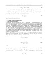
The measurement results of the TOF velocity distribution for a CdTe BC target ablated with
220 mJ laser pulses are shown in Fig. 10.
The solid lines being theoretical fits to experimental points are obtained with the use of Eq.
(7). The theoretical curve fits in Fig. 10, as well as those in Figs. 11–13 are performed with
the computer application Origin 7.0 with the option of the least squares method. The values
of the velocities u and v
0
obtained from those fitting are given in the inserts to the figures. In
0 200 400 600 800 1000 1200 1400 1600
0,0
0,2
0,4
0,6
0,8
1,0
Cd, 220 mJ
Normalized QMS Signal
u = 535 m/s
v
0
= 155 m/s
v [m/s]
0 200 400 600 800 1000 1200 1400 1600
0,0
0,2
0,4
0,6
0,8
1,0
u = 520 m/s
v
0
= 152 m/s
Normalized QMS Signal
Te, 220mJ
0 200 400 600 800 1000 1200 1400 1600
0,0
0,2
0,4
0,6
0,8
1,0
Normalized QMS Signal
u = 500 m/s
v
0
= 148 m/s
v [m/s]
Te
2
, 220mJ
Fig. 10. TOF velocity distributions for atoms of Cd and Te and diatomic molecules, Te
2
.
Results are for CdTe BC target ablated with 220 mJ laser pulses with frequency of 25 Hz.
Solid curves are obtained from theoretical fit to the experimental points with help of Eq. (7).
Fitting parameters u and v
0
are given in inserts. For Cd fit with Eq. (4) is also made and
shown as dashed curve for comparison.
Laser Pulse Phenomena and Applications
342
the case of Cd, the fit with u = 0 is also given for comparison. This is in effect a fit to the TOF
distribution of the classic M-B distribution (Eq. (4)). It is clear from the comparison that the
experimental distributions are rather narrow, and thereby have to be described by the TOF
shifted M-B distribution (Eq. (7)). It is seen in Fig. 10 that the fit with Eq. (7) is rather good,
and therefore the values of the velocities u and v
0
are determined with a fairly good
accuracy. The description of the experimental distributions with Eq. (7) means that the
Knudsen layer is formed, hence the particles encounter collisions.
The velocity distribution for the CdTe PP target is determined for two laser pulse energies:
280 mJ and 160 mJ. The results are shown in Fig. 11.
0 200 400 600 800 1000 1200 1400 1600
0,0
0,2
0,4
0,6
0,8
1,0
u = 328 m/s
v
0
= 240 m/s
u = 581 m/s
v
0
= 224 m/s
Normalized QMS Signal
Te, 280 mJ
Te, 160 mJ
0 200 400 600 800 1000 1200 1400 1600
0,0
0,2
0,4
0,6
0,8
1,0
Normalized QMS Signal
u = 579 m/s
v
0
= 224 m/s
Cd, 160 mJ
u = 348 m/s
v
0
= 227 m/s
Cd, 280 mJ
0 200 400 600 800 1000 1200 1400 1600
0,0
0,2
0,4
0,6
0,8
1,0
u = 219 m/s
v
0
= 223 m/s
u = 595 m/s
v
0
= 220 m/s
Normalized QMS Signal
v [m/s]
Te
2
, 280 mJ
Te
2
, 160 mJ
u = 219 m/s
v
0
= 223 m/s
u = 595 m/s
v
0
= 220 m/s
Te
2
, 280 mJ
Te
2
, 160 mJ
u = 219 m/s
v
0
= 223 m/s
u = 595 m/s
v
0
= 220 m/s
Te
2
, 280 mJ
Te
2
, 160 mJ
u = 219 m/s
v
0
= 223 m/s
u = 580 m/s
v
0
= 226 m/s
Te
2
, 280 mJ
Te
2
, 160 mJ
Fig. 11. TOF velocity distributions for atoms of Cd and Te and diatomic molecules Te
2
.
Results are for CdTe PP target ablated with 280 mJ and 160 mJ laser pulses of 25 Hz
frequency. Solid curves are obtained from theoretical fit to experimental points with the
help of Eq. (7). Fitting parameters u and v
0
are given in the inserts.
It is seen that the velocity distributions for the 280 mJ pulses are shifted to higher velocities,
as may be expected. It is also observed that the theoretical fit to the experimental points is
generally good, with the exception of the low velocity side for the 280 mJ pulses. The
existence of the "low velocity tail" for the 280 mJ pulses can be ascribed to the target
overheating, which results in the emission of the low energy particles of the heat origin, as
described in Sec. 3. In the case of the 280 mJ pulses we observe, as in the BC target case, a
close similarity between all particle distributions, leading to very close values of the most
probable velocity. On contrary, in the case of 160 mJ pulses, the most probable velocity of
the diatomic molecules is clearly smaller than those of the monatomic particles.
Ablation of 2-6 Compounds with Low Power Pulses of YAG:Nd Laser
343
The results of the TOF velocity distribution measurements for the CdTe N-PP target ablated
with 160 m J pulse energies are shown in Fig. 12.
0 200 400 600 800 1000 1200 1400 1600
0,0
0,2
0,4
0,6
0,8
1,0
u = 555 m/s
v
0
= 168 m/s
Normalized QMS Signal
Te, 160 mJ
0 200 400 600 800 1000 1200 1400 1600
0,0
0,2
0,4
0,6
0,8
1,0
Normalized QMS Signal
Cd, 160 mJ
u = 545 m/s
v
0
= 177 m/s
0 200 400 600 800 1000 1200 1400 1600
0,0
0,2
0,4
0,6
0,8
1,0
u = 520 m/s
v
0
= 145 m/s
Normalized QMS Signal
v [m/s]
Te
2
, 160 mJ
Fig. 12. TOF velocity distributions for atoms of Cd and Te and diatomic molecules Te
2
.
Results are for CdTe N-PP target ablated with 160 mJ laser pulses of 25 Hz frequency. Solid
curves are obtained from theoretical fit to experimental points with the help of Eq. (7).
Fitting parameters u and v
0
are given in the inserts.
It may be seen that even for this relatively small pulse energy, the velocity distributions are
affected by the low temperature tail. This low temperature tail is particularly clearly
observed in the case of Te
2
molecules. This may be understood, because the Te
2
diatomic
molecules are larger in number than the monatomic Te in the particle stream emitted
thermally from an overheated target. The distributions for the CdTe N-PP target are similar
to those of CdTe PP target of the CdTe PP target ablated with 280 mJ pulses. This means that
due to a smaller thermal conductivity of the CdTe N-PP target, the effective temperature of
the target ablation is for that target higher. This also confirms the conclusion of Sec. 3 that at
the same laser pulse energy the effectiveness of the laser ablation of a N-PP target is higher
in comparison with a PP target.
The TOF velocity distributions for CdSe and ZnTe are measured for PP targets with 160 mJ
laser pulse energies and the frequency of 25 Hz. They are shown in Fig. 13.
Like in the case of the CdTe PP target, the particle velocity distributions for CdSe and ZnTe are
narrow and show “the low velocity tail”, which is more clearly seen for ZnTe. Therefore, the
general features of the distributions are dependent on the compound chemical composition.
Laser Pulse Phenomena and Applications
344
200 400 600 800 1000 1200 1400 1600
0,0
0,2
0,4
0,6
0,8
1,0
u = 646 m/s
v
0
= 235 m/s
Normalized QMS Signal
Zn,160 mJ
v [m/s]
200 400 600 800 1000 1200 1400 1600
0,0
0,2
0,4
0,6
0,8
1,0
u = 481 m/s
v
0
= 198 m/s
Normalized QMS Signal
Cd, 160 mJ
v [m/s]
200 400 600 800 1000 1200 1400 1600
0,0
0,2
0,4
0,6
0,8
1,0
Te, 160 mJ
Normalized QMS Signal
u = 575 m/s
v
0
= 196 m/s
v [m/s]
200 400 600 800 1000 1200 1400 1600
0,0
0,2
0,4
0,6
0,8
1,0
u = 465 m/s
v
0
= 264 m/s
Normalized QMS Signal
Se, 160 mJ
v [m/s]
200 400 600 800 1000 1200 1400 1600
0,0
0,2
0,4
0,6
0,8
1,0
u = 515 m/s
v
0
= 183 m/s
Normalized QMS Signal
v [m/s]
Te
2
, 160 mJ
200 400 600 800 1000 1200 1400 1600
0,0
0,2
0,4
0,6
0,8
1,0
u = 451 m/s
v
0
= 172 m/s
Normalized QMS Signal
Se
2
, 160 mJ
v [m/s]
Fig. 13. TOF velocity distributions for CdSe PP and ZnTe PP targets ablated with 160 mJ
laser pulses of frequency of 25 Hz Solid curves are obtained from theoretical fit to
experimental points with the help of Eq. (7). Fitting parameters u and v
0
are given in the
inserts.
4.3 Particle velocity distribution: Discussion and conclusions
In the present studies is observed substantial narrowing of the velocity distributions for all
types of targets. The physical parameters of the gas phase, as determined form the best fit of
the data in Figs. 10 – 13, are compiled in Table 1.
Ablation of 2-6 Compounds with Low Power Pulses of YAG:Nd Laser
345
Target
energy
pulse
[mJ]
particle
v
0
[m/s]
u
[m/s]
c
[m/s]
T
[K]
v
0,r
[m/s]
T
r
[K]
M
[–]
Cd
155 535 141 159 577 2200 3.8
BC, 220 Te
152 520 139 178 561 2424 3.7
CdTe Te
2
148 500 135 337 541 4499 3.7
Cd
224 579 204 332 656 2843 2.8
PP, 280 Te
224 581 204 386 657 3326 2.8
CdTe Te
2
226 580 206 786 658 6660 2.8
Cd
227 348 207 341 460 1400 1.7
PP, 160 Te
240 328 215 443 455 1592 1.5
CdTe Te
2
223 219 311 766 358 1973 0.7
Cd
177 545 162 207 597 2361 3.4
N-PP 160 Te
168 555 153 217 602 2789 3.6
CdTe Te
2
145 520 132 324 558 4789 3.9
Zn
235 646 215 219 722 2072 3.0
PP, 160 Te
196 575 179 296 635 3109 3.2
ZnTe Te
2
183 515 167 516 573 5062 3.1
Cd
198 481 181 259 552 2016 2.7
PP, 160 Se
264 466 241 327 585 1606 1.9
CdSe Se
2
172 451 157 278 509 2432 2.9
Table 1. Particle stream parameters emitted from various targets.
The first column in the table shows the target preparation method and material, the second
column gives the energy of the laser shot at which the target was ablated, and the third
column specifies the emitted particles. The fourth and the fifth columns present respectively
the values of the most probable particle velocity
0
v in the frame of COM system and the
COM velocity, u in the laboratory system. In the eighth column values of most probable
velocity in the laboratory system
0,r
v are given. If u >
0
v
as it is in the present case, the most
probable velocities given by Eqs. (8) and (6) are rather close. In the present case,
0,r
v is
smaller than
0,TOF
v by about 20%. This may be verified by comparing the values of
0,r
v in
the table with the values of
0,TOF
v read out from the distribution maxima in Figs 10 – 13. We
prefer to present in the table the values of
0,r
v because they are not directly associated with
the measurement method (TOF).
To
0,r
v one can formally ascribe temperature T
r
according to the equation analogous to the
relationship described by Eq. (3):
2
0,
2
r
r
mv
kT =
, (9)
where T
r
is a certain measure of the average kinetic energy, in the laboratory system, of
particles subjected to the adiabatic expansion. Because it describes the gas phase after its