Management and Services Part 13 pptx
Bạn đang xem bản rút gọn của tài liệu. Xem và tải ngay bản đầy đủ của tài liệu tại đây (402.56 KB, 7 trang )
Realization of lowpass and bandpass leapfrog lters using OAs and CCCIIs 77
jjj
YVI ,
11
jjj
VVV
11
iii
III
,
iii
IZV
,
111
nnn
YVI ,
nnn
VVV
21
and
11
nnn
III ,
nnn
ZIV (4)
Where ),,5,3,1( ni and ),,6,4,2( nj
. Equation (4) can be represented by leapfrog
block diagram depicted in Fig. 4, where the output signal of each block is fed back to the
summing point input of the preceding block. In contrast with the conventional simulation
topology, however, we will present a simple, systematic and more efficient method unique
to active-only current mode ladder filters by using the features of an OA and a CCCII.
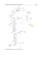
Fig. 3. General resistively terminated current-mode ladder prototype
Fig. 4. Leapfrog block diagram of the general ladder prototype of Fig. 3
3.1 Lowpass leapfrog realization
As an example to illustrate the design procedure, consider the current-mode 3rd-order all-
pole LC ladder lowpass prototype with regarding the terminating resistors shown in Fig. 5.
The design techniques of these partial conversions can be accomplished in the way as
shown in Fig. 6, through the use of only an OA and a CCCII as mentioned. Therefore, the
circuit parameters have the typical values calculated by
ii
xi
CB
R
1
for ni ,,7,5,3,1
and
jjxj
LBR for 1,,8,6,4,2
nj (5)
Where B
k
(k=i or j)represents the GBP of the k-th OA.
Based on the directed simulation of the LC branch as shown in Fig. 6, the system diagram
thus straightforwardly derived from the passive RLC ladder circuit of Fig. 5 can be shown
in Fig. 7. The design equations of the circuit parameters can be expressed as follows
LSx
RRRR
11
1
1
CB
R
x
222
LBR
x
and
33
3
1
CB
R
x
(6)
Note that all elements, which simulate the behavior of capacitor and inductor, are tunable
electronically through adjusting the resistor parameters, R
x
.
Fig. 5. 3rd-order all-pole LC ladder lowpass prototype
iCi
IZV
ii
xi
CB
R
1
(a) parallel branch impedance
jLj
VYI
jjxj
LBR
(b) series branch admittance
Fig. 6. Partial branch simulations using OA and CCCII of the lowpass network of Fig. 5
Management and Services 78
Fig. 7. Systematic diagram for current-mode 3rd-order lowpass filter using active-only
elements
3.2 Bandpass leapfrog realization
The proposed approach can also be employed in the design of current-mode LC ladder
bandpass filters. Consider the current-mode 6th-order LC ladder bandpass prototype shown
in Fig. 8, having parallel resonators in parallel branches and series resonators in series
branches. Observe that the repeated use of the bandpass LC structure branches typically
consisting of parallel and series combinations of capacitor and inductor, shown respective in
Figs.9(a) and 9(c), makes up the complete circuit. The voltage-current characteristic of these
partial operations can be derived respectively as follows
)(
1
)(
i
i
i
i
iLiCi
sL
V
I
sC
VYIZV
(7)
for ni ,,7,5,3,1 .
)(
1
)(
j
j
j
j
jCjLj
sC
I
V
sL
IZVYI
(8)
for 1,,8,6,4,2
nj .
Fig. 8. 6th-order LC ladder bandpass prototype
)(
iLiCi
VYIZV
i
a
i
a
xi
LBR ,
i
b
i
b
xi
CB
R
1
(a) (b)
)(
jCjLj
IZVYI
j
a
j
a
xj
LBR
,
j
b
j
b
xj
CB
R
1
(c) (d)
Fig. 9. Sub-circuit simulation using all-active elements of the bandpass network of Fig. 8
The resulting circuits for the active-only implementation of these structures corresponding
to the sub-circuit operations of Fig. 9(a) and 9(c) are then resulted in Figs.9(b) and 9(d),
respectively. The design formulas for the circuit parameters of each branch can be
summarized below
RRRR
LSx
i
a
i
a
xi
LBR ,
i
b
i
b
xi
CB
R
1
and
j
a
j
a
xj
LBR ,
j
b
j
b
xj
CB
R
1
(9)
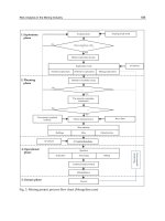
The structure realization diagram of the bandpass filter, thus obtained by directly replacing
each sub-circuit from Fig. 9 into the ladder bandpass prototype of Fig. 8, can be shown in
Fig. 10.
Realization of lowpass and bandpass leapfrog lters using OAs and CCCIIs 79
Fig. 7. Systematic diagram for current-mode 3rd-order lowpass filter using active-only
elements
3.2 Bandpass leapfrog realization
The proposed approach can also be employed in the design of current-mode LC ladder
bandpass filters. Consider the current-mode 6th-order LC ladder bandpass prototype shown
in Fig. 8, having parallel resonators in parallel branches and series resonators in series
branches. Observe that the repeated use of the bandpass LC structure branches typically
consisting of parallel and series combinations of capacitor and inductor, shown respective in
Figs.9(a) and 9(c), makes up the complete circuit. The voltage-current characteristic of these
partial operations can be derived respectively as follows
)(
1
)(
i
i
i
i
iLiCi
sL
V
I
sC
VYIZV
(7)
for ni ,,7,5,3,1 .
)(
1
)(
j
j
j
j
jCjLj
sC
I
V
sL
IZVYI
(8)
for 1,,8,6,4,2
nj .
Fig. 8. 6th-order LC ladder bandpass prototype
)(
iLiCi
VYIZV
i
a
i
a
xi
LBR ,
i
b
i
b
xi
CB
R
1
(a) (b)
)(
jCjLj
IZVYI
j
a
j
a
xj
LBR
,
j
b
j
b
xj
CB
R
1
(c) (d)
Fig. 9. Sub-circuit simulation using all-active elements of the bandpass network of Fig. 8
The resulting circuits for the active-only implementation of these structures corresponding
to the sub-circuit operations of Fig. 9(a) and 9(c) are then resulted in Figs.9(b) and 9(d),
respectively. The design formulas for the circuit parameters of each branch can be
summarized below
RRRR
LSx
i
a
i
a
xi
LBR ,
i
b
i
b
xi
CB
R
1
and
j
a
j
a
xj
LBR ,
j
b
j
b
xj
CB
R
1
(9)
The structure realization diagram of the bandpass filter, thus obtained by directly replacing
each sub-circuit from Fig. 9 into the ladder bandpass prototype of Fig. 8, can be shown in
Fig. 10.
Management and Services 80
Fig. 10. Systematic diagram for current-mode 6th-order bandpass filter using active-only
elements
Since all circuit parameters depend on R
x
the values, a property of the proposed filter
implementations is, therefore, possible to tune the characteristic of the current transfer
function proportional to external or on-chip controlled internal resistance R
x
. It is shown
that for the employment of all active elements, a further advantage is to allow integration in
monolithic as well as in VLSI fabrication techniques.
4. Simulation results
To demonstrate the performance of the proposed ladder filter, a design of current-mode
3rd-order Butterworth lowpass filter of Fig. 7 with a cut-off frequency of f
c
=100kHz was
realized. This condition leads to the component values chosen as follows,
1
x
R kΩ,
5.106
31
xx
RR Ω, 87.18
2
x
R kΩ. The simulated result shown in Fig. 11 exhibits
reasonably close agreement with the theoretical value. For another illustration a sixth-order
Chebyshev bandpass filter response of Fig. 10 is also designed with the following
specifications: center frequency = 50kHz, bandwidth = 1.0 and ripple width = 0.5dB. The
approcimation of this filter resulted in the following components values:
1
x
R kΩ, 765.11
31
a
x
a
x
RR kΩ, 33.33
31
b
x
b
x
RR Ω, 62.20
2
a
x
R kΩ, 41.58
2
b
x
R Ω.
The simulated response of the designed filter verifying the theoretical value is shown in Fig.
12. In these simulations, The implementations of 0.25μm CMOS OAs, 0.25μm CMOS CCCII
and their aspect ratio with ±2 volts power supplies are illustrated in Fig. 13 and Fig. 14,
respectively
[13-14]
. The W/L parameters of MOS transistors are given in Table 2 and 3,
respectively. The CMOS OAs using
30
1
C pF with bias voltage
1B
V and
2B
V set to -1V
and -2V, respectively.
Fig. 11. Simulated frequency response of Fig. 7
Fig. 12. Simulated frequency response of Fig. 10
Fig. 13. CMOS OA implementation
Fig. 14. CMOS CCCII implementation
Realization of lowpass and bandpass leapfrog lters using OAs and CCCIIs 81
Fig. 10. Systematic diagram for current-mode 6th-order bandpass filter using active-only
elements
Since all circuit parameters depend on R
x
the values, a property of the proposed filter
implementations is, therefore, possible to tune the characteristic of the current transfer
function proportional to external or on-chip controlled internal resistance R
x
. It is shown
that for the employment of all active elements, a further advantage is to allow integration in
monolithic as well as in VLSI fabrication techniques.
4. Simulation results
To demonstrate the performance of the proposed ladder filter, a design of current-mode
3rd-order Butterworth lowpass filter of Fig. 7 with a cut-off frequency of f
c
=100kHz was
realized. This condition leads to the component values chosen as follows,
1
x
R kΩ,
5.106
31
xx
RR Ω, 87.18
2
x
R kΩ. The simulated result shown in Fig. 11 exhibits
reasonably close agreement with the theoretical value. For another illustration a sixth-order
Chebyshev bandpass filter response of Fig. 10 is also designed with the following
specifications: center frequency = 50kHz, bandwidth = 1.0 and ripple width = 0.5dB. The
approcimation of this filter resulted in the following components values:
1
x
R kΩ, 765.11
31
a
x
a
x
RR kΩ, 33.33
31
b
x
b
x
RR Ω, 62.20
2
a
x
R kΩ, 41.58
2
b
x
R Ω.
The simulated response of the designed filter verifying the theoretical value is shown in Fig.
12. In these simulations, The implementations of 0.25μm CMOS OAs, 0.25μm CMOS CCCII
and their aspect ratio with ±2 volts power supplies are illustrated in Fig. 13 and Fig. 14,
respectively
[13-14]
. The W/L parameters of MOS transistors are given in Table 2 and 3,
respectively. The CMOS OAs using
30
1
C pF with bias voltage
1B
V and
2B
V set to -1V
and -2V, respectively.
Fig. 11. Simulated frequency response of Fig. 7
Fig. 12. Simulated frequency response of Fig. 10
Fig. 13. CMOS OA implementation
Fig. 14. CMOS CCCII implementation
Management and Services 82
Transistor W L
(μm) (μm)
Transistor W L
(μm) (μm)
M
1
, M
2
250 3 M
6
392 1
M
3
, M
4
100 3 M
7
232 3
M
5
80 32 M
8
39 1
Table 2. Transistors aspect ratio of COMS OA
Table 3. Transistors aspect ratio of COMS CCCII
5. Conclusion
This paper presented an alternative systematic approach for realizing active-only current-
mode ladder filters based on the leapfrog structure of passive RLC ladder prototypes. The
proposed design approach are realizable with only two fundamental building blocks, i.e.,
OA and CCCII, which does not require any external passive elements. A property of this
approach is the possibility of tuning the current transfer function by the controlled
resistance R
x
. Because of their active-only nature, the approach allows to realize filtering
functions which are suitable for implementing in monolithic integrated form in both bipolar
and CMOS technologies as well as in VLSI fabrication techniques. Since the synthesis
technique utilizes an internally compensated pole of an OA, it is also suitable for high
frequency operation. The fact that simulation results are in close agreement with the
theoretical prediction verified the usefulness of the proposed design approach in current-
mode operations.
6. References
[1] Nagasaku T, Hyogo A and Sekine K. A synthesis of a novel current-mode operational
amplifier, Analog Integrated Circuits and Signal Processing, 1996, 1(11):183.
[2] Wu J. Current-mode high-order OTA-C filters. International Journal of Electronics, 1994,
76:1115.
[3] Abuelma’atti M T and Alzaher H A. Universal three inputs and one output current-mode
filter without external passive elements. Electronics Letters, 1997, 33:281.
[4] Singh A K and Senani R. Low-component-count active-only imittances and their
application in realizing simple multifunction biquads. Electronics Letters, 1998,
34:718.
[5] Tsukutani T, Higashimura M, Sumi Y and Fukui Y. Electronically tunable current-mode
active-only biquadratic filter. International Journal of Electronics, 2000,87:307.
[6] Tsukutani T, Higashimura M, Sumi Y and Fukui Y. Voltage-mode active-only biquad.
International Journal of Electronics, 2000,87:1435.
Transistors W(μm) L(μm)
M
1
,M
3
, M
7
, M
11
, M
13
, M
15
, M
17
,
M
19
5 0.5
M
2
,M
4
, M
12
, M
14
, M
16
, M
18
15 0.5
M
8
14.2 0.5
M
5
, M
9
2 0.5
M
6
, M
10
4 0.5
[7] Gerling F E J and Good E F. Active filters 12: the leapfrog or active-ladder synthesis.
Wireless Word, 1970, 76(1417): 341.
[8] Tangsrirat W, Fujii N and Surakampontorn W. Current-mode leapfrog ladder filters
using CDBAs, Circuits and Systems, 2002, 12(5): 26.
[9] Tangsrirat W, Dumawipata T and Unhavanich S. Design of active-only highpass and
bandpass leapfrog filters using multi-current-output differentiators, Electronics,
Circuits and Systems, 2003, 5(1): 14.
[10] Tangsrirat W, Dumawipata T and Unhavanich S. Realization of lowpass and bandpass
leapfrog filters using OAs and OTAs, SICE 2003 Annual Conference, 2003, 4(3): 4.
[11] Fragoulis N and Haritantis I. Leapfrog-type filters that retain the topology of the
prototype ladder filters, IEEE international symposium on circuits and systems,
2000, 5(6): 161.
[12] Prommee P, Kumngern M, Dejhan K. Current-mode active-only universal filter Circuits
and Systems, APCCAS, 2006:896.
[13] Eser S, Ozcan S, Yamacli S et al. Current-mode Active-only universal bi-quad filter
employing CCIIs and OTAs. 2009 international conference on applied electronics,
sep 9-10, Pilsen, Czech Republic,2009, 107-110.
[14] Pipat Prommee, Montri Somdunyakanok and Kobchai Dejhan. Universal filter and its
oscillator modification employing only active components. 2008 International
symposium on intelligent signal processing and communications systems, Jan 8-10,
Bangkok, Thailand, 2009, 1-4.
Realization of lowpass and bandpass leapfrog lters using OAs and CCCIIs 83
Transistor W L
(μm) (μm)
Transistor W L
(μm) (μm)
M
1
, M
2
250 3 M
6
392 1
M
3
, M
4
100 3 M
7
232 3
M
5
80 32 M
8
39 1
Table 2. Transistors aspect ratio of COMS OA
Table 3. Transistors aspect ratio of COMS CCCII
5. Conclusion
This paper presented an alternative systematic approach for realizing active-only current-
mode ladder filters based on the leapfrog structure of passive RLC ladder prototypes. The
proposed design approach are realizable with only two fundamental building blocks, i.e.,
OA and CCCII, which does not require any external passive elements. A property of this
approach is the possibility of tuning the current transfer function by the controlled
resistance R
x
. Because of their active-only nature, the approach allows to realize filtering
functions which are suitable for implementing in monolithic integrated form in both bipolar
and CMOS technologies as well as in VLSI fabrication techniques. Since the synthesis
technique utilizes an internally compensated pole of an OA, it is also suitable for high
frequency operation. The fact that simulation results are in close agreement with the
theoretical prediction verified the usefulness of the proposed design approach in current-
mode operations.
6. References
[1] Nagasaku T, Hyogo A and Sekine K. A synthesis of a novel current-mode operational
amplifier, Analog Integrated Circuits and Signal Processing, 1996, 1(11):183.
[2] Wu J. Current-mode high-order OTA-C filters. International Journal of Electronics, 1994,
76:1115.
[3] Abuelma’atti M T and Alzaher H A. Universal three inputs and one output current-mode
filter without external passive elements. Electronics Letters, 1997, 33:281.
[4] Singh A K and Senani R. Low-component-count active-only imittances and their
application in realizing simple multifunction biquads. Electronics Letters, 1998,
34:718.
[5] Tsukutani T, Higashimura M, Sumi Y and Fukui Y. Electronically tunable current-mode
active-only biquadratic filter. International Journal of Electronics, 2000,87:307.
[6] Tsukutani T, Higashimura M, Sumi Y and Fukui Y. Voltage-mode active-only biquad.
International Journal of Electronics, 2000,87:1435.
Transistors W(μm) L(μm)
M
1
,M
3
, M
7
, M
11
, M
13
, M
15
, M
17
,
M
19
5 0.5
M
2
,M
4
, M
12
, M
14
, M
16
, M
18
15 0.5
M
8
14.2 0.5
M
5
, M
9
2 0.5
M
6
, M
10
4 0.5
[7] Gerling F E J and Good E F. Active filters 12: the leapfrog or active-ladder synthesis.
Wireless Word, 1970, 76(1417): 341.
[8] Tangsrirat W, Fujii N and Surakampontorn W. Current-mode leapfrog ladder filters
using CDBAs, Circuits and Systems, 2002, 12(5): 26.
[9] Tangsrirat W, Dumawipata T and Unhavanich S. Design of active-only highpass and
bandpass leapfrog filters using multi-current-output differentiators, Electronics,
Circuits and Systems, 2003, 5(1): 14.
[10] Tangsrirat W, Dumawipata T and Unhavanich S. Realization of lowpass and bandpass
leapfrog filters using OAs and OTAs, SICE 2003 Annual Conference, 2003, 4(3): 4.
[11] Fragoulis N and Haritantis I. Leapfrog-type filters that retain the topology of the
prototype ladder filters, IEEE international symposium on circuits and systems,
2000, 5(6): 161.
[12] Prommee P, Kumngern M, Dejhan K. Current-mode active-only universal filter Circuits
and Systems, APCCAS, 2006:896.
[13] Eser S, Ozcan S, Yamacli S et al. Current-mode Active-only universal bi-quad filter
employing CCIIs and OTAs. 2009 international conference on applied electronics,
sep 9-10, Pilsen, Czech Republic,2009, 107-110.
[14] Pipat Prommee, Montri Somdunyakanok and Kobchai Dejhan. Universal filter and its
oscillator modification employing only active components. 2008 International
symposium on intelligent signal processing and communications systems, Jan 8-10,
Bangkok, Thailand, 2009, 1-4.