Advances in Lasers and Electro Optics Part 5 potx
Bạn đang xem bản rút gọn của tài liệu. Xem và tải ngay bản đầy đủ của tài liệu tại đây (7.72 MB, 50 trang )
Artificial Intelligence Tool and Electronic Systems Used to Develop Optical Applications
187
case is determined by the control of the XY displacements. In absence of the servo motors
implementation, manual control can be also carried out, keeping the reliability of the
measurements, due to the worm drives coupled to the XY table. Similar structures can be
realized on the base of the meter presented here, for example, using recycled printer rails or
making mechanical structures of low cost. The bigger inversion would be realized on the
detection circuit, which involves the DSPIC programming. A total scanning area, at least at
20x20 cm
2
is suitable in order to realize measurements of the luminaries of larger sizes. Also
it is suggested to be very careful in the selection of all parts of the prototype, because as we
mentioned, the little variations for example in the gear teeth can produce deviations in the
generated profiles.
The implementation of the rectangular meter permits to observe with a great detail the
profile produced as a result of the beamwidth of the illumination source under test. The
generated information permits us to realize a comparison with other spherical prototype
developed by our research group, and to have complete information about the total
irradiance profile. The rectangular prototype provides empirical information necessary not
only for manufacturers, but also for research activities. We found this prototype very useful
due to the controllability of position, which increases the feasibility of the measurements, and
provides a very complete irradiance pattern for the case of directive illumination sources. The
application of the XY table automation shows the high potential of this type of devices.
3. An artificial intelligence development tool to micro engraved with laser
(MGL) to control and optimization of the laser engrave process
The purpose of this project is to make devices that can be used in the optical fiber sensors,
which requires micrometric dimension engrave. The process consists of two AutoCAD
design that acts as reproduction by controlling 2 steps motors adapted to move X, Y axis
mechanism. Case Based Reasoning (CBR) methodology is used to optimize the process. In a
simple way, CBR resolves a new problems (new case) by a comparison with the other
resolved problems (case library), it takes one or more solutions from the most similar cases,
the proposed solution is evaluated and if it is necessary, this is adapted. Finally, if the
proposed solution solves the problem, the new case is saved in the case library, in contrary
case, it is not saved and the comparison continues. In this way, the systems infers
knowledge or experience, given better results in accordance with its case library extension.
The laser power approach is obtained under this procedure, as a function of the new
material properties (per example, the hardness). The comparison of the specific properties
with other cases or materials already characterized, makes possible to optimize the process
by reducing engraving probes in new materials.
Nowadays, any line of development or research depends on the existing materials and
equipment in other areas or development lines very near to it. This it is the case of the area
of sensors and optical fibers, which depends mainly on the development of equipment in
the communication area, where they are mutilated or modified with other pieces to be able
to be used. This kind of problem can be reduced, if each device, considering its material, is
designed and made in accordance to the proposed procedure.
The main problem is to make devices in order to apply them in the area of sensors from
common materials. This entails two new problems:
• To characterize the materials
• Method of engraving
Advances in Lasers and Electro Optics
188
The devices fabrication can be realized by several methods, such as (Trimmer, 2005):
• Micro mechanized by ablation laser
• Micro mechanized by diamond
• Micro perforated
• Stereolithography or micro molded photo
• LEAGUE (X-ray lithography with metalized)
• Using Excimer laser
From the previous methods, if the purpose is to reduce the costs of the project to the
minimum, the most viable for us is the one of engraving laser. For its utilization, it is
necessary to account with a high-power laser and the possibility of using different materials
from waste (like wood, plastic, paper, among others) to realize the engraving tests. The
laboratory of Optics of CIICAp has all these conditions, making possible to realize here all
test for the engrave laser process.
Based on the previous research, two lines of work are considered:
1. To characterize the materials to use (like the dimension and depth of penetration of the
channel) by means of the CBR Technique (Software), and
2. To design a mechanical device to control the displacements in X and Y axes
In CBR systems, in order to adapt and evaluate a possible solution, frequently it is necessary
to consider new recovered cases (representing the problem as a case). There are many cycles
in the process (figure 25). Each case typically contains a description of the problem
(attributes or characteristics of the problem), a solution and its result (García et al., 2005).
Fig. 25. Basic Cycle of CBR.
In order to find the laser power to use in a new material: the new case (material) is
compared against the cases in the case library by means of the near neighbor technique
based on the equation 2.
Artificial Intelligence Tool and Electronic Systems Used to Develop Optical Applications
189
Similarity
(2)
where:
T is the new case
S is the case source
n is the number of attributes in each case
i is an individual attribute from 1 until n
f is the function of similarity for attributes i in cases T and S
W is the importance (the weight) of attribute i
The weights of each attribute are assigned by the expert (a person that assigns the weight to
the attributes based on the quality of the engraving), which are designated by an annotation
generally going from 0 to 1. For example: the hardness of the material has a weight of 0.60
whereas the translucence has a weight of 0.05. But, not all the attributes (characteristic of the
material) are not taken into account, such as the case of the material color, since it is not
useful for the analysis.
The values of similarity between the materials change whenever a new material is added to
the case library. While greater it is the number of attributes (n) and it is counted on an
extensive Case Library, the time in calculating this similarity will be greater for example, if
we have 5 attributes in each case and a case library with 100 cases, 500 calculations cases will
be realized (5*100). Some authors recommend having a base of cases smaller than 100 cases
(Lake, 1996).
The recovered more similar cases are used to suggest a solution that is reused and tried on
successfully. In case of being necessary, the solution will be reviewed and adapted by the
expert. In addition the expert can make a suggestion like adding wet paper or other
techniques that help to obtain an engraving with greater quality. Finally, the present
problem and the final solution are conserved as a new case (material characterized). Any
solution and/or characteristic of some material can be modified later by the user; while
more cases have the system will be able to approach an ideal solution for the engraving of a
new more case.
The calculation tool was developed with the programming language Java SDK standard
edition 1.42 with more than 3.000 classes (Chan, 2002), along with JBuilder X, they are used
to create applications in graphics mode multiplatform (Easttom, 2003). It was necessary to
use usesPort and parport-win32 libraries for the shipment and reception of data by the
parallel port. The user interface is based on the principle of easy and friendly software
(Schildt, 2001).
The system is based on the following process for the accomplishment of the engraving (see
Figure 26):
1. The user uses software to interchange the design created in AutoCAD to another one
with DXF extension, in ASCII code (Tajadura, 1999). At the moment, designs with lines
are only processed (command line).
2. The software only has the data necessary to realize traces (lines made in Autocad),
reducing the size of the DXF archive. It transforms the simpler archive MGL (with the
same name but with the extension mgl).
3. The user selects the material of the materials base. In case of being a new material, it is
added to the system providing its characteristics. The system realizes the CBR process
Advances in Lasers and Electro Optics
190
to suggest the power for the new material, on the base of the resolute cases (material
characterized) and the tests of the new material. The fundamental parameters
considered for the engraving quality are: the power for engraving and the focal
distance, while for the material are: basically the hardness and the roughness, for future
analysis the new cases also would consider: information about translucent, heat
resistance, and metallic or not metallic characteristics.
4. Continuing with the process, the user selects the lens for the engraving considering the
focal length and the diameter of the focal point.
5. The software based on the Autocad file of the design, kept with the extension mgl,
realizes the outlines through a communication stage (parallel port), to control the
displacement of a milli-machined table. The objective is to control the rotation of the
two motors. An improve in the mechanical system was realized by adding the a
variable height, and a third motor, which functions as an shutter in order to avoid not
desired engravings.
6. At the end the tool, the description of the engraving will be required to the user, using
the RBC. The information is stored in the bookstore of cases to make future
comparisons between engravings, in order to find an optimized design giving a
solution improved for the task that the user wishes to realize. The RBC contribution in
the control software is to suggest the power required for engraving in order to reduce
the range of the necessary tests for the characterization of the new material. The
characterized cases are considered to realize the similarity process.
Fig. 26. Schematic diagram of the operation of the calculation tool for the engraving with
laser.
Artificial Intelligence Tool and Electronic Systems Used to Develop Optical Applications
191
The material characterization has been realized considering 4 different tests, based on:
• The focal distance
• The laser power
• Variations on the exposition time
• Traces and sizes (using an Autocad template)
The focal distance tests permits to determine the smallest possible diameter of the focal
point. The variable power test produced, depending of the material characteristics, a
proportional dependence between the damage and the applied power; the utilization of
RBC, by the accumulated experience permits to reduce the range of realized tests. The
variation in the exposition time produced the best defined channels, but it takes a lot of
time. The variations in trace and sizes tests provide satisfactory results, in spite of some
mechanical problems.
The application of CBR to the system produced satisfactory results, better than of those than
it was expected, such as the realization of engravings with channels less wide than the same
optical fiber (approx. 145 µm) and engravings become attached to the dimensions in the
design obtaining in this way a significant advance in spite of the used equipment. The
quality of the engraving also depends of the used material. The system continues under
development. The present work outlines a prototype with currently obtained results.
It can be concluded that the system has wide possibilities to be more than a tool used in the
devices design for sensing area, due to its capacity for both, to engrave and to realize cuts in
different materials. The following stage of this project will be the accomplishment of a
communication interface between a Palm and a mechanical system by means of electronics
to control the precise movements of servo motors, as well as a more reliable and precise
mechanical system. Another stage would be to control a new parameter, the displacement in
Z axis, which would permit to control the depth of the engraving as well as arcs, ellipses
and other more complex geometric figures.
4. Computer tool for engraving by means of PDA (Personal Digital Assistant)
based on RBC
This section describes a computing tool on the Interface Development Environment (IDE),
that was developed in an environment of development Code Warrior V9, in "C" language.
This IDE accounts with an emulator, which allows to make tests before installing the
program in the PDA. The goal of this tool is to characterize materials through the Artificial
Intelligence technique named Case-Based Reasoning (CBR), with the help of this technique
and a few of instructions, the characterization of the materials can be optimized. The
development consist in choosing a few of parameters that allow us to do the search in the
case library through the CBR and then process the data in the PDA. The information is send
to the serial port, which after is sent to the receptor that transmits it to the motors.
The engraving techniques in their origins were realized by equipment of great sizes.
Nowadays the computers are more and more small and economic, and so the use of the
CNC (Computerized Numerical Control) has been extended to all type of machinery:
winches, rectifiers, machines to sew, among others.
Development of a measure tool, that through CBR, handles the information of different
materials
The objective is to characterize materials besides executing the program in a portable device
that allows the adaptation of the user to the work area. The device that will serve like
Advances in Lasers and Electro Optics
192
control is a PDA that has capacity of processing and data storage. These devices count with
series and infrared ports. The difference between them is that first one depends on a
physical connection, while the infrared does not. The series port requires of wires, but they
can be larger than the corresponding to parallel port, and the number of wires is smaller.
The pines Tx, Rx and GND of the connector DB9 are used to connect the PDA to the
microcontroller. The data conversion is realized by means of the UART module.
The final mission is to characterize material through a complete system that includes our
proposed calculation tool, a control module and actuators, as well as a laser.
The CBR is a technique of Artificial intelligence, its methodology is used in our computer
tool. The CBR allows having an optimization in the characterization of the materials; some
of the data that are being handled to be keeping in the case library are: material name,
thickness, translucence, and the figure to be engraved. The CBR accounts with a basic cycle
(See Figure 27) that includes the four r’s:
• To recover the case(s) more similar;
• To reuse the case(s) to try to solve the problem;
• To review the propose solution in case of necessity, and
• To retain the new solution as it leaves from a new case.
Fig. 27. The Basic Cycle of RBC [adapted of the proposed by (Aamodt & Plaza, 1994)].
A new problem is compared against cases in the cases library and the more similar cases are
recovered. A solution is suggested as a result of the similarity analysis, which later is reused
and tested in order to achieve the success of the solution. Unless the recovered case is a very
similar case, the solution will probably have to be reviewed producing a new case that can
be conserved. This cycle happens, currently, rarely without the human intervention (see
figure 28). For example many tools of CBR (Ochoa et al., 2004) act mainly as recovery of the
case and reutilizing systems. The revision of the case (also call adaptation) is realized often
by the ones in charge of the Case Library. Nevertheless, this does not have to be seen like
debility of the CBR, since it permits to work as a tool of making decision, with the human
collaboration in aid of the best decision (Wainer et al., 2005).
The Code Warrior V9, under the "C" programming language, provides an atmosphere,
which allows to build an interface of easy handling for the user. The diagram of figure 28
shows how the system works.
Artificial Intelligence Tool and Electronic Systems Used to Develop Optical Applications
193
Fig. 28. Blocks under which the developed tool works.
This process begins when choosing the kind of the design to realize from:
1. Predetermined design or
2. Design at free hands,
If the first option is chosen, a window is opened, where the user has a series of designs
previously made, after the selection of one of them is realized, the next step is to introduce
data of the material to use. A new window with a list of materials is displayed; if the desired
material is not previously registered previously in the list, the program provide a series of
fields for fulfill its corresponding information. With this information the system realizes
tests if it is desired, to acquire a suggested power for engraving. This last data is obtained
with all the previously acquired data and processed by the methodology of CBR (Morales et
al., 2005).
In this way, the program accounts with all necessary information to complete the process
and send the information through the series port to the control module of the actuators. The
procedure concludes with the laser engraving (figure 29).
Fig. 29. Conceptual diagram, showing the Process of control by means of PDA.
The computer tool was development to realize different tests of engraving, as in the case of
the system shown in section 2. About the hardware, the motors are moved bi-directionally,
they are controlled by a PALM and have the capability to realize different types of
trajectories to engrave surfaces. Several tests were realized with texts engraving. The use of
recyclable material permits the development of the system with minimum costs.
Advances in Lasers and Electro Optics
194
The system is in the stage of finals tests and runs in a PALM 100m (Wilding-McBride, 2004),
the electronic module already is in operation; and the bookstore of cases accounts with
information of different materials. It is tried that this system can be used from any place
where the user is located by means of Internet (WWW). In addition, the possibility to
storage more parameters of the materials provides more precision in their characterization.
5. Future trends
The technique called Electrochemical Machining (ECM) is an anodic dissolution process. It
utilizes an electrolytic cell formed by a cathode tool and an anode workpiece with a suitable
electrolyte flowing between them. The anode workpiece is dissolved according to Faraday’s
law when a sufficient voltage is applied across the gap between the anode and the cathode
in which electrolyte is filled. Electrochemical processes for drilling small and fine holes by
controlled anodic dissolution invariably use a weak acidic solution as electrolyte (Shan,
2004). These include electrochemical drilling (ECD) and acid based ECM drilling processes:
shaped tube electrolytic machining (STEM), capillary drilling (CD), electro-stream drilling
(ESD), and jet electrolytic drilling (JED). The advantages of acid based electrochemical hole
drilling processes are:
• Good surface finish;
• Absence of residual stress;
• No tool wear;
• No burr and no distortion of the holes;
• Simultaneous drilling of large number of holes.
The use of acid electrolytes in ECM hole drilling processes facilitate dissolution of metals and
the removed material is carried away as metal ions thus making it possible to achieve smooth
finish with closer tolerances and deep holes of high aspect ratio (Bellows and Kohls, 1982).
Another Laser (continuous or pulsed) technique named Laser Beam Machining (LBM) is one
of the most used techniques, based on thermal energy, of type non-contact. This process can
be applied for almost whole range of materials. The lasers used for machining in the
industries are CO
2
and Nd:YAG. This two lasers are the most stable. In this kind of work,
the use of power and focusing are everything needed to monitor.
The mechanism of material removal during LBM includes different stages such as
a. Melting,
b. Vaporization, and
c. Chemical degradation (chemical bonds are broken which causes the materials to
degrade).
If a high energy density laser bream is focused on the work surface the thermal energy is
absorbed, which heats and transforms the work volume into a molten, vaporized or
chemically changed state that can easily be removed by flow of high pressure assist gas jet
(which accelerates the transformed material and ejects it from machining zone) (Hirao et al.,
2001). The schematic of LBM is shown in figure 30.
The interesting part is that each material possess a different response to the light. Some
interesting materials have been studies as drilling of gamma-titanium aluminide (Biswas et
al, 2009). Among the most important materials in optoelectronic devices, the Glass is found,
with a high transmission from the UV to IR wavelength region, excellent thermal and
electrical properties, and high chemical resistivity (Weber, 2003; Hirao et al., 2001).
Furthermore, the glass properties are controllable by adjusting the composition during
Artificial Intelligence Tool and Electronic Systems Used to Develop Optical Applications
195
Fig. 30. Basic setup of LBM
development and fabrication. However, these properties make the glass a challenging
material to machine (Herman, 2000). Due to poor thermal properties, fabrication of finely
machined features using laser-based processes e.g. grooves, channels, microholes, stand-
alone levers, etc., in glass materials has been quite a difficult task.
Laser technologies based on nanosecond (ns), femtosecond (fs) and laser-induced plasma
processing were investigated in order to obtain high quality laser micro-fabricated features
on glass materials. Direct write laser using short pulses from ns and fs lasers influences the
quality of processed glass significantly and produces crack-free, clean machining with
careful control of the associated thermal processes. Laser-induced plasma machining
technique allows fabrication of small-size, shallow features along with superfine surface
finishes within the channels. The potential of these technologies have benefits in the
fabrication of complex features for biomedical, microfluidic, MEMS and optoelectronic
devices.
6. Conclusions
This work confirms the relevance of the automation in optics applications. For the
realization of all the prototype, it was required of a multidisciplinary team, involving
basically programming, electronics and optics knowledge.
7. References
Aamodt, A. & Plaza, E. “Case-Based Reasoning: Foundational Issues, Methodological
Variations, and System Approaches. AI Communications, 7(i): pp 39-59.
Bellows G., Kohls J.B., Drilling without drills, American Machinist, Special Report 743 (1982)
173–188.
Biswas R., Kuar A.S., Sarkar S., Mitra S. "A parametric study of pulsed Nd:YAG lases micro-
drilling of gamma-titanium aluminide". Optics & Laser Technology, In Press,
Corrected Proof, Available online 20 May 2009.
Chan, Patrick “The Java Developers ALMABAC 1.4, volume 1”, Addison Wesley 2002.
Easttom, Check “JBuilder 8.0 JFC and Swing”, Wordware Publishing; 2003.
Advances in Lasers and Electro Optics
196
García, Luis A.; Basurto-Pensado, Miguel & Ochoa, Alberto. “Herramienta de Cómputo
para Grabado con Láser”, Universidad Autónoma de Zacatecas, ENINVIE 2005.
Gonzalez-Roman A., Tecpoyotl-Torres M., Escobedo-Alatorre J., Pal-Verma S. and Sánchez-
Mondragón J. “A semi-spherical Irradiance meter used as a quality control device”.
Proceedings of the First Multiconference on Electronics and Photonics. MEP 2006.
Pp. 253- 256 (2006).
Gwirc, S.; Rigotti, J.; Federico, A.;Acquaticci, F. 6o. Jornada de desarrollo e innovación
tecnológica. Imágenes Ultrasónicas con Transductor Piezoeléctrico de Película.
Instituto Nacional de Tecnología Industrial, (2007).
Herman P.R., Marjoribanks R.S., Oettl A., Chen K., Konovalov I., Ness S., Appl. Surf. Sci.
154/155 (2000) 577.
Hirao K., Mitsuyu T., Si J., Qiu J. (Eds.), Active Glass for Photonic Devices: Photoinduced
Structures and Their Application, Springer-Verlag, 2001.
James C. Maida. “An illumination modeling system for human factor analyses”. Space human
factors laboratory/Flight crew support division/NASA Johnson Space Center.
Jaimes-Vera Edith Alíne, Basurto– Pensado M.A., Escobedo-Alatorre J. Jesus. Diseño y
programación de una mesa para mili-maquinado., ENINVIE 2005. Encuentro de
Investigación en Ingeniería Eléctrica, 2005.
Lake, David B., “Case-Based Reasoning- Experiences, Lessons, & Future Directions”, Edit.
The MIT Press 1996.
Morales, J.; Basurto, M. & Ochoa, A. “Herramienta de Cómputo para Grabado mediante
PDA”, Zacatecas, Zacatecas 2005.
Ochoa A. et al. “Proceedings of Doctoral Forum, PRICAI 2004, Auckland University of
Technology, August 2004.
Palais, Joseph C., Fiber Optic Communications, Fourth Edition, Prentice Hall, (1984).
Paul Horowitz, Winfield Hill. The Art of Electronics. 2nd Edition. Cambridge University
Press. Pp. 996. 2001.
Sánchez-Mondragón, J., Tecpoyotl-Torres M., Andrade-Lucio J. A., Torres-Cisneros M.,
Dávila-Alvarez A. and Carpio-Valadez M “Data fitting on a spherical shell”.
Proceedings of SPIE proceeding Vol. 5181. Pp.51-55 (2003).
Schildt, H. “Java 2: The Complete Reference, Fourth Edition”, Edit. McGraw Hill 2001.
Shan H.S., Advanced Manufacturing Methods, New Delhi, 2004.
Tajadura, J.A. et Al. “Autocad 2000 Avanzado”, Edit. Mc Graw Hill, 1999.
Tecpoyotl-Torres M, Partida-Rivera E., Gonzalez-Roman I. A., Ibarra-Manzano O. and
Sánchez- Mondragón J "Reconstruction of atmospheric vertical reflectivity profile
images". Proceedings of the First Multiconference on Electronics and Photonics.
MEP 2006. Pp. 262-265. IEEE CN 06 Ex1524. (2006).
Trimmer, William “Micromechanics and MEMS” Wiley & IEEE book, ISBN 0-7803-1085-3,
2005.
Yañez Valdez, R. *, M. Ruiz Torres, E. Morales Sánchez, E. Castillo Castañeda. Diseño y
Construcción de una Mesa de Trabajo XYθ basada en un Mecanismo Paralelo
Planar 3RRR. Tecnólog@ Vol. 1, No. 2, may- ago/2008 © 2007 CICATA-Querétaro-
IPN. ISSN en trámite. México.
Wainer, J.; Borgonovi, Luana & Ochoa, A. “Ornithological Classification using case-based
reasoning for discovered new species”, UNICAMP Postdoctoral program;
Radamaelli, Brazil. January 2005.
Weber M.J. (Ed.), Handbook of Optical Materials, The CRC Press, Boca Raton, Fl. 2003.
Westinhouse. Manual del alumbrado. 4ª edición. Limusa. Noriega Editores. Madrid (2000).
Wilding-McBride, Darly. Java Development on PDAs, Addison-Wesley 2001.
11
Theory of Unitary Spin Rotation
and Spin State Tomography
for a Single Electron and Two Electrons
T. Takagahara
Department of Electronics and Information Science,
Kyoto Institute of Technology, Matsugasaki, Kyoto 606-8585
CREST, Japan Science and Technology Agency,
4-1-8 Honcho, Kawaguchi, Saitama 332-0012,
Japan
1. Introduction
Coherent control of quantum states is a critical step toward many novel technological
applications ranging from manipulation of quantum bits (qubits) in quantum logic gates to
controlling the spin degrees of freedom of electrons [1–13]. A qubit with a longer coherence
time is desirable for the application to the quantum information processing. Electron spins
in semiconductor nanostructures are considered as one of the most promising candidates of
the building blocks for quantum information processing due to their robustness against
decoherence effects [14–18]. A quantum media converter between a photon qubit and an
electron spin qubit was proposed for the use in quantum repeaters [19–22]. Quantum
information can take several different forms and it is preferable to be able to convert among
different forms. One form is the photon polarization and another is the electron spin
polarization. Photons are the most convenient medium for sharing quantum information
between distant locations. Electrons are the most efficient medium for manipulating the
quantum information by electrical and optical means. The fundamental operations are the
initialization, unitary rotation and measurement of a qubit. The initialization of a single
electron spin was demonstrated by the efficient optical method [23–25]. Also, the coherent
rotation of a single electron spin has been realized by the microwave ESR (Electron Spin
Resonance) method [26] and by the optical STIRAP (STImulated Raman Adiabatic Passage)
method with coherence times up to several µs [27–33] in III-V semiconductor nanostructures
and up to several tens of ms in the localized electron systems in IV elemental
semiconductors [34–36]. The optical STIRAP method is advantageous because of its ultrafast
operation. However, the precise control of the spin rotation without leaving behind any
population in the intermediate excited states has not yet been realized. It is also important to
achieve the unitary spin rotation of two electrons, because the singlet-triplet subspace of two
electrons was utilized as a qubit space and the electrical manipulation of the qubit was
realized [16]. At the same time, it is absolutely necessary to confirm the quantum state of the
electron after the spin state manipulation or the quantum state transfer from a photon,
namely, to examine whether the electron spin is prepared in the desired state or not. This
Advances in Lasers and Electro Optics
198
requires the full state tomography, namely the measurement of the density matrix of the
electron. This state tomography is also important to estimate the fidelity of relevant
quantum operations.
Thus it is a challenging task to establish the precise spin rotation and the spin state
tomography for both cases of a single electron and two electrons. We review the general
aspects of the unitary spin rotation of a single electron by the STIRAP method and develop
the scheme to rotate the pseudo-spin formed by the singlet state and the triplet states of two
electrons based on the optical STIRAP process, discussing the optimal conditions for the
precise control. Also we propose and analyze optical methods to achieve the electron spin
state tomography based on the Faraday/Kerr rotation, referring to the recent experiments
[37, 38].
2. Optical STIRAP method for spin rotation of a single electron
As mentioned in the Introduction, the spin rotation of a single electron is a crutial ingredient
in the quantum information processing. It is desirable to accomplish the spin rotation along
an arbitrary direction for an arbitrary rotation angle in a single-shot process. So far, the spin
rotation of a single electron was demonstrated by optical and electrical means in the
proofof- principle experiments. With respect to the required time for the spin rotation, the
optical method based on the STIRAP (stimulated Raman adiabatic passage) process is
preferable because of its ultrafast response. But the precise control of the spin rotation is yet
to be pursued. Here several characteristics of this STIRAP process will be investigated.
Fig. 1. Schematic energy level structure for the STIRAP process. Allowed optical transitions
are depicted by x and y, which represent the mutually orthogonal polarizations. Δ denotes
the off-resonance energy of the excitation lights relative to the transition energies. The
Raman condition for the excitation lights is imposed.
In order to carry out the STIRAP process, a Λ-type transtion is necessary, as depicted in Fig.
1. The lowest two levels denoted by |x〉 and |
〉 are the ground doublet states with close
energies, e.g., the spin up and spin down states of a single electron or the ground and
excited vibrational states of a single molecule. A pseudospin is composed of these doublet
states and can be rotated by optical transitions via the intermediate excited state denoted by
|T〉. The important point is that the selection rules of the left and right optical transitions are
orthogonal to each other, which are depicted typically as x and y in Fig. 1. The doublet
states are not directly connected optically. Then the relevant Hamiltonian is written as
(1)
Theory of Unitary Spin Rotation and Spin State Tomography
for a Single Electron and Two Electrons
199
(2)
(3)
where H
0
represents the unperturbed part, V the optical transitions, Ω
x
and Ω
y
the Rabi
frequencies, δ the relative phase shift of the y-polarized light and the energy E
x
is put as
E
x
= 0 for the origin of energy. Then the time evolution proceeds as follows:
(4)
(5)
In order to single out the rapidly oscillating part, we put as
(6)
obtaining
(7)
Now we postulate the Raman condition for the x and y polarized lights:
(8)
and also assume the same pulse shape for the x- and y-polatized lights with arbitrary
relative intensity ratio determined by θ:
(9)
Introducing the bright and dark state amplitudes defined by
(10)
we can simplify the equations of motion as
(11)
Thus the dark state does not change. The amplitudes of the bright state and the |T
〉 state
satisfy the following equations:
Advances in Lasers and Electro Optics
200
(12)
(13)
To develop the analytical solutions of these equations [39, 40], we assume a sech pulse
envelope:
(14)
Introducing a dimensionless time variable by
(15)
we have
(16)
(17)
This is a hypergeometric differential equation. General solutions are given by
(18)
(19)
where F(α, β, γ|ζ) is the hypergeometric function. In the rotation of the pseudospin, we start
with the initial state in which
(20)
and after the pulse we prefer to have
Theory of Unitary Spin Rotation and Spin State Tomography
for a Single Electron and Two Electrons
201
(21)
in order to leave no excitation in the intermediate excited state |T
〉. To satisfy this condition,
we should have
(22)
because the asymptotic behavior (t→∞) is given by putting as ζ = 1. Using the formula [41]
(23)
which is valid under the condition that Re(c − a − b) > 0 and c ≠ 0, −1, −2, …, we have
(24)
Further, using the formulas
(25)
we obtain
(26)
Putting in the expression of γ, we finally have
(27)
This quantity vanishes only when α = 1, 2, … . This condition is nothing but the condition
that the pulse area is 2π, 4π, … . This is quite reasonable because the Bloch vector rotates
and returns to the initial state for the pulse area of integer times 2π.
Furthermore, under this condition, the amplitude of the bright state receives after a pulse an
additional factor given by
(28)
where the expressions on the right hand side correspond to α = 1, 2, 3, … , respectively and
their absolute magnitude is obviously unity and thus they can be put as
(29)
This phase φ determines the rotation angle of the pseudospin, as will be shown shortly.
Now the effect of the pulse can be summarized as
Advances in Lasers and Electro Optics
202
(30)
This relation can be rewritten in terms of
amplitudes:
(31)
where the operation of the pulse is calculated as
(32)
(33)
This relation indicates that the pseudospin vector composed of |x〉 and |
〉 states is rotated by
an angle φ around the direction vector
. The rotation angle φ can be tuned by the off-
resonance energy Δ in Eq. (8), whereas the direction vector
can be adjusted by the
intensity ratio and the relative phase shift between the orthogonally polarized lights with
the same temporal envelope.
In order to estimate the fidelity of this spin rotation, we prepare an arbitrary initial state,
follow the time evolution to obtain the asymptotic state, calculate the overlap with the ideal
state and average over the initial states. In order to take into account relaxation processes,
we consider the density matrix for the system composed of three states. We prepare an
initial state:
(34)
(35)
(36)
where θ
i
and ϕ
i
indicate the initial direction of the pseudospin. The time evolution of the
density matrix is given by
(37)
where ¡ includes the population relaxation and decoherence terms. After the time evolution
we have the asymptotic state π(∞), which is actually π(T
f
) for a large enough time T
f
, and
calculate the fidelity defined by the overlap of the actual density matrix with the ideal
density matrix which is obtained without any relaxation terms:
(38)
Theory of Unitary Spin Rotation and Spin State Tomography
for a Single Electron and Two Electrons
203
where the angular bracket means the average over the initial spin direction, namely:
(39)
Some numerical results will be presented for the fidelity and the residual population in the
excited state |T
〉. Because of the energy-time duality the following results can be applied for
an arbitrary pulse width by scaling appropriately the off-resonance energy. But, for the
definiteness, the optical pulse is assumed as sech (t/t
p
) with t
p
= 5ps and the time evolution
is integrated over the time range of −6t
p
≤ t ≤ 6t
p
. The relaxation parameters are chosen as
(40)
where Γ(γ) indicates the population relaxation (decoherence) rate. The equations of motion
for the density matrix elements are similar to those given from Eq. (58) to Eq. (64) in the later
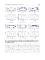
section. First of all, the rotation angle φ is plotted in Fig. 2 as a function of the off-resonance
energy. The normalized off-resonance energy is defined by Δt
p
, where Δ is given in Eq. (8),
and is dimensionless. For the 2π pulse the rotation angle is monotonically increasing with
increasing off-resonance. The fidelity of the spin rotation is exhibited in Fig. 3. The fidelity is
improved with increasing off-resonance in general for the 2π and 4π pulses. For the 6π
pulse, a strange behavior is seen. But it can be understood that a fidelity peak appears
around the off-resonance energy where the rotation angle is almost 360 degrees, namely, the
spin returns to the initial state and the deviation from the ideal time evolution is suppressed.
Another important quantity is the residual population in the excited state |T
〉 and is
exhibited in Fig. 4. This is monotonically decreasing with increasing off-resonance.
Fig. 2. Angles of the spin rotation are plotted as a function of the normalized off-resonance
energy Δt
p
for the pulse areas of (a) 2π, (b) 4π, (c) 6π, (d) 8π, and (e) 10π.
Analytically exact solutions are possible only for the sech pulses. In order to see the effect of
the pulse shape, a Gaussian pulse is examined for the case of 2π pulse area. Results are
exhibited in Figs. 5 and 6 and show that the sech pulse is better for the higher fidelity and
the smaller population left in the excited state after the pulse.
Advances in Lasers and Electro Optics
204
Fig. 3. Fidelity of the spin rotation of a single electron is plotted as a function of the
normalized off-resonance. Curves (a), (b) and (c) correspond to the pulse area 2π, 4π and 6π,
respectively.
Fig. 4. Residual population in the excited state |T
〉 after the spin rotation of a single electron
is plotted as a function of the normalized off-resonance. Curves (a), (b) and (c) correspond to
the pulse area 2π, 4π and 6π, respectively.
So far we have considered a typical Λ-type system composed of three energy levels.
However, in the case of a singly charged semiconductor quantum dot, there are at least two
excited states, namely the trion states, associated with two spin directions of the hole state.
Thus, the four level system, as depicted in Fig. 7, is more appropriate. The fidelity of the
spin rotation for the four level system is examined using the parameters:
(41)
(42)
(43)
Theory of Unitary Spin Rotation and Spin State Tomography
for a Single Electron and Two Electrons
205
where the Raman condition is applied to the left Λ-type transition. Results are given in Fig.
8 and show that the fidelity is not degraded by an additional Λ-type transition, especially
for the 2π pulse area. Thus the spin rotation is expected to be robust against the overlap of
several Λ-type transitions.
Fig. 5. Fidelity of the spin rotation of a single electron is compared between the cases of a
Gaussian pulse and a sech pulse for the 2π pulse area.
Fig. 6. Residual population in the excited state |T 〉 after the spin rotation of a single electron
is compared between the cases of a Gaussian pulse and a sech pulse for the 2π pulse area.
Fig. 7. Four level system composed of two electron spin states (lower levels) and two trion
states with different hole spin states (upper levels). Allowed optical transitions are indicated
by the x and y polarizations.
Advances in Lasers and Electro Optics
206
Fig. 8. Fidelity of the spin rotation of a single electron is plotted as a function of the
normalized off-resonance in the four-level model. Curves (a), (b) and (c) correspond to the
pulse area 2π, 4π and 6π, respectively.
3. Optical STIRAP method for spin rotation of two electrons
Now we extend the above arguments to the spin rotation of two electrons. This spin rotation
is important because a qubit composed of the singlet state and one of the triplet states of two
electrons confined in a semiconductor quantum dot was established and its electrical
manipulation was demonstrated16. Here we examine the possibility of ultrafast spin otation
of two electrons by an optical means. As discussed above, the essential ingredient is the Λ-
type transition with mutually orthogonal optical selection rules which enables the spin
rotation of an arbitrary angle along an arbitrary direction. In the Faraday configuration the
allowed optical transitions are exhibited in Fig. 9. The charged exciton state is depicted by
X
2−
. An additional superscript indicates the spin direction of the electron in the excited
orbital state and an additional subscript represents the spin direction of the heavy hole in
the lowest energy orbital state, namely,
(44)
where the left hand side indicates the missing state of the valence band electron in the state
on the right hand side. There is a Λ-type transition but with the same optical selection rules.
Thus the arbitrary spin rotation is not possible.
On the other hand, for the Voigt configuration in which a magnetic field is applied along the
quantum dot plane (taken as the x axis), the optical selection rules are exhibited in Fig. 10 for
the case associated with the light hole state. Here, an additional superscript attached to X
2−
indicates the spin direction of the electron in the excited orbital state, namely, +(-) for the
x(−x) direction and an additional subscript represents the spin direction of the light hole in
the lowest energy orbital state, namely, Ah+ or Ah− corresponding to
(45)
Theory of Unitary Spin Rotation and Spin State Tomography
for a Single Electron and Two Electrons
207
Fig. 9. Allowed optical transitions in the Faraday configuration for two electrons. The lower
levels represent the four spin states of two electrons: the singlet (S) and three triplet (T
1
, T
0
,
T
−1
) states, whereas the upper levels exhibit the negatively doubly charged exciton states
(X
2−
) with indexes indicating the spin state of the electron in the excited orbital and the spin
state of the heavy hole.
Fig. 10. Allowed optical transitions in the Voigt configuration for two electrons. The lower
levels represent the four spin states of two electrons: the singlet (S) and three triplet (T
1
, T
0
,
T
−1
) states, whereas the upper levels exhibit the negatively doubly charged exciton states
(X
2−
) with indexes indicating the spin state of the electron in the excited orbital and the spin
state of the light hole.
where the left hand side indicates the missing state of the valence band electron in the state
on the right hand side. Then we find that the spin rotation by STIRAP is possible except for
cases of the pseudospin composed of (S, T
0
) and (T
1
, T
−1
). The same situation holds also for
transitions associated with the heavy hole. As seen in Fig. 10, the four levels in both the
ground and excited states are energetically close to each other. In the excited states, they are
lying within the range determined by the Zeeman energy difference, which is about several
tens of µeV for 1 Tesla. In the ground states, the singlet state lies below the triplet states by
the orbital excitation energy and the triplet states are close to each other within the Zeeman
energy difference.
It is important to examine the fidelity of the spin rotation under the situation that several Λ-
type transitions are overlapping within a similar energy range. As a model system we
consider a five-level system as depicted in Fig. 11. Relative energy differences, population
relaxation and decoherence rates employed are
(46)
(47)
(48)
Advances in Lasers and Electro Optics
208
Fig. 11. Five level system composed of three lower levels and two upper levels. This is a
simplest idealized model for studying the effect of overlapping Λ-type transitions.
Concerning the four levels composed of |0〉, | 1〉, |2〉 and |3〉, the relevant parameters are the
same as for the four-level system in Fig. 7. Thus, the effect of an additional level |4〉 can be
examined. Results are exhibited in Fig. 12. An additional level degrades the coherence of the
STIRAP process and reduces the fidelity of the spin rotation. However, in the case of 2π
pulse area, the fidelity keeps a good value for large off-resonance energies.
Fig. 12. Fidelity of the spin rotation of two electrons is plotted as a function of the
normalized off-resonance in the five-level model. Curves (a), (b) and (c) correspond to the
pulse area 2π, 4π and 6π, respectively.
Another important feature is the state initialization within the pseudospin subspace. When
we want to rotate the pseudospin composed of |0〉 and |2〉 states in Fig. 11, the state should
be initialized within this subspace. We examined the effect on the fidelity of the spin
rotation of the incomplete state initialization. The fidelity is calculated for the case in which
the state is prepared in the subspace spanned by the |0〉 and |2〉 states with the weight of 0.9
and in the |4〉 state with the weight of 0.1. Results are given in Fig. 13 with those for the
complete initialization in which the state is prepared in the subspace spanned only by the |0〉
and |2〉 states. The fidelity loss proportional to the deviation from the perfect initialization is
seen. Thus the state initialization should be carried out as perfect as possible. One possible
way of the state initialization is the use of the singlet-triplet level crossing by the magnetic
field tuning. At first we prepare the two electrons in the singlet state and then bring the
system adiabatically to the crossing point. During the residence period at the crossing point,
Theory of Unitary Spin Rotation and Spin State Tomography
for a Single Electron and Two Electrons
209
the state mixing is induced by the spin-orbit interaction and the hyperfine interaction with
nuclei, leading to an incoherent mixed state. This incoherent mixed state is sufficient to carry
out the spin rotation. When the electron Zeeman energy is sufficiently large and three triplet
states are well separated, the state initialization within the subspace composed of two
crossing states such as (S, T
1
), (S, T
0
) and (S, T
−1
) will be established.
Fig. 13. Fidelity of the spin rotation of two electrons is plotted as a function of the
normalized off-resonance in the five-level model for two cases, namely, one case where
initially the population is prepared within the states |0〉 and |2〉 with 90% weight and in the
state |4〉 with 10% weight and the other case where the population is prepared within the
subspace spanned only by |0〉 and |2〉. The pulse area is 2π.
4. Spin state tomography of a single electron
The projective measurement of the spin state of a single electron is possible based on the
Faraday/Kerr rotation of a linearly polarized light and this has been demonstrated
experimentally very recently [42,43]. However, in the spin state tomography, all the
components of the spin (s
x
, s
y
, s
z
), namely, the off-diagonal (coherence) components as well
as the diagonal components of the density matrix should be measured. The density matrix
of a single electron spin in the spin up and down bases is given by
(49)
(50)
where σ
i
(i = x, y, z) is the Pauli spin matrix. The purity of this state is given by
(51)
Thus, by measuring all the components (s
x
, s
y
, s
z
) we can determine whether the state is a
pure state or not.
Advances in Lasers and Electro Optics
210
In order to measure all the components (s
x
, s
y
, s
z
) by an optical means, there should be at
least one excited state which is connected to both the spin up and spin down states of the
electron, in other words, there should be a Λ -type transition. This transition creates the
coherence between the spin up and spin down states, rotates the spin and enables the spin
state tomography. It is easily shown that such a Λ -type transition is not possible in the
Faraday configuration. On the other hand, in the Voigt configuration in which an in-plane
magnetic field is applied along, e.g., the x direction, the Λ-type transition is possible as
depicted in Fig. 14 for the optical transitions associated with both the heavy hole and light
hole states. In Fig.14, the optical polarization selection rules are given in the x and y bases.
The excited state is a trion state composed of a spin-singlet electron pair and a hole. The
electron and hole states under an in-plane magnetic field are described by
(52)
(53)
(54)
where for the hole states the left hand side represents the missing state of the valence band
electron in the state on the right hand side.
Fig. 14. Λ-type transitions for a single electron in the Voigt configuration. The lower levels
indicate the two spin states of the electron, whereas the upper levels represent the trion
states associated with the light hole or the heavy hole states. The polarization selection rules
are given in terms of the x and y bases, where the in-plane magnetic field is applied in the x
direction.
Now we discuss the scheme to measure the spin component of the electron. A probe light
propagates along the z axis and its polarization rotation is measured in the transmission or
reflection geometry. Thus the dielectric tensor represented in the bases of the electric field
components in the x and y directions is relevant. In the theoretical analysis a single Λ-type
transition will be considered with the level indexes as depicted in Fig. 15. An external test
field is applied to estimate the dielectric tensor and is assumed as
(55)
where
is the unit vector in the x(y) direction. The initial density matrix, which is to be
fixed from the measurements, is given by
Theory of Unitary Spin Rotation and Spin State Tomography
for a Single Electron and Two Electrons
211
Fig. 15. A Λ-type transition is chosen from the left hand side of Fig. 14 and the levels are
numbered to simplify theoretical expressions.
(56)
where the bases are chosen as |0〉, |2〉 and |1〉. The relevant equations of motion for the
density matrix take the form:
(57)
where H
0
and V are similar to those in Eqs. (2) and (3) and Γ includes the population
relaxation and decoherence terms. Expressions for each matrix element are given below:
(58)
(59)
(60)
(61)
(62)
(63)
(64)
where
is the optical matrix element between the states |i〉 and |j〉 for the light polarization
in the k direction, E
i
the energy of the state |i〉, Γ
i→j
the population decay rate from the state
|i〉 to the state |j〉 and γ
ij
is the decay rate of the coherence between the states |i〉 and |j〉. In
order to facilitate the analysis, the rapidly oscillating parts will be separated out as
(65)
where
and are slowly varying amplitudes. ρ
02
is also slowly varying because ω
02
is
very small compared with the optical transition energies. Then the equations of motion for
these amplitudes become