Advances in Lasers and Electro Optics Part 17 docx
Bạn đang xem bản rút gọn của tài liệu. Xem và tải ngay bản đầy đủ của tài liệu tại đây (13.12 MB, 50 trang )
Quantitative Phase Imaging using Multi-wavelength Optical Phase Unwrapping
781
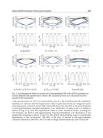
Fig. 9. Three-wavelength optical phase unwrapping of cheek cells using ring dye laser.
Image size is 103 μm per side. (a) direct image of the cheek cell; (b) a single wavelength
phase map; (c) three-wavelength coarse map; (d) three-wavelength fine map with reduced
noise; (e) 3-D rendering of (d).
appears in darker color. The final fine map with reduced noise is shown in Fig. 10(c). Figure
10(d) is the 3-D rendering of the final fine map. In the final unwrapped phase map, the
width of the top of the groove is measured along the line shown in Fig. 4(d). The measured
width is 44 μm.
Advances in Lasers and Electro optics
782
Fig. 10. Three-wavelength optical phase unwrapping of LP record grooves. Image size is 102
μm per side; (a) a single wavelength phase map; (b) three-wavelength coarse map; (c) three-
wavelength fine map with reduced noise; (d) 3-D rendering of (c). The grove width is 44 μm.
Cross-sections and phase noise of the coarse and fine maps are shown in Fig.11. Figure 11(a)
is the unwrapped coarse map and Fig. 11(b) is the final fine map with reduced noise. Figure
11(c) is the surface profile of the coarse map along the line shown in Fig. 11(a). The RMS
noise in the coarse map in the area shown is 2.12 μm and this is shown in Fig. 11(d). Figure
11(e) shows the surface profile of fine map along the line shown in Fig. 11 (b). The groove
depth h = 18 μm.
Quantitative Phase Imaging using Multi-wavelength Optical Phase Unwrapping
783
Fig. 11. Surface profiles of LP record grooves. (a) three-wavelength coarse map, (b) three-
wavelength fine map with reduced noise, (c) surface profile of coarse map along the line
shown in (a); (d) noise in coarse map in the area shown in (a). RMS noise is 2.12 μm ; (e)
surface profile of fine map along the line shown in (b). The groove depth h = 18 μm ; (f)
noise in the fine map in the area shown in (b). RMS noise is 1.36 μm.
5. Summary
In summary, this chpater demonstrates the effectiveness of the multi-wavelength optical
unwrapping method. To our knowledge this is the first time that three wavelengths have
been used in interferometry for phase unwrapping without increasing phase noise. Unlike
conventional software phase unwrapping methods that fail when there is high phase noise
and when there are irregularities in the object, the multi-wavelength optical phase
unwrapping method can be used with any type of object. Software phase unwrapping
algorithms can take more than ten minutes to unwrap phase images. This is a disadvantage
when one needs to study live samples in real time or near – real time. The multi-wavelength
optical unwrapping method is significantly faster than software algorithms and can be
effectively used to study live samples in real time. Another advantage is that the
Advances in Lasers and Electro optics
784
optical phase unwrapping method is free of complex algorithms and needs less user
intervention.
The method is a useful tool for determining optical thickness profiles of various microscopic
samples, biological specimens and optical components. The optical phase unwrapping
method can be further improved by adding more wavelengths, thus obtaining beat
wavelengths tailored for specific samples.
6. References
Charette, P. G.; Hunter, I. W. (1996). Robust phase-unwrapping method for phase images
with high noise content. Applied Optics, Vol. 35, Issue 19, (July 1996), pp. 3506-3513,
ISSN 0003-6935.
Cheng, Y; Wyant, J. C. (1984). Two-wavelength phase shifting interferometry. Applied Optics,
Vol. 23, Issue 24, (December 1984), pp. 4539-4543, ISSN 0003-6935.
Cheng, Y.; Wyant, J. C. (1985). Multiple-wavelength phase-shifting interferometry. Applied
Optics, Vol. 24, Issue 6, (March 1985), pp. 804-807, ISSN 0003-6935.
Creath, K.; Cheng, Y.; Wyant, J. C. (1985). Contouring aspheric surfaces using two-
wavelength phase-shifting interferometry. Journal of Modern Optics, Vol. 32, No. 12,
(December 1985), pp. 1455-1464, ISSN 0950-0340.
Dilhaire,S.; Grauby, S.; Jorez, S.; Lopez, L. D. P.; Rampnoux, J.; Claeys, W. (2002). Surface
displacement imaging by interferometry with a light emitting diode. Applied Optics,
Vol. 41, Issue 24, pp.4996-5001, (August 2002),ISSN 0003-6935.
De Groot, P.; Kishner, S. (1991). Synthetic wavelength stabilization for two color laser-diode
interferometry. Applied Optics, Vol. 30, Issue 28, pp 4026-4033 (October 1991), ISSN
0003-6935.
Fedeyev, V.; Haber, C. C. (2003). Reconstrcution of mechanically recorded sound by image
processing. LBNL Report 51983, 2003.
Fercher, A.; Drexler, W.; Hitzenberger, C. K.; Lasser, T. (2003). Optical coherence
tomography - principles and applications. Reports on Progress in Physics, Vol. 66, pp.
239-303 (January 2003).
Gass, J.; Dakoff, A.; Kim, M. K. (2003). Phase imaging without 2π ambiguity by
multiwavelength digital holography. Optics Letters, Vol. 28, Issue 13, (July 2003),
pp. 1141-1143, ISSN 0146-9592.
Ghiglia,D. C.; Romero, L. A. (1994). Robust two-dimensional weighted and unweighted
phase unwrapping that uses fast transforms and iterative methods. Journal of the
Optical Society of America A, Vol. 11, No. 1, (January 1994), pp. 107-117, ISSN 1084-
7529.
Ishii, Y.; Onodera, R. (1995). Phase-extraction algorithm in laser-diode phase shifting
interferometry. Optics Letters, Vol. 20, Issue 18, pp. 1883-1885 (September 1995),
ISSN 0146-9592.
Liu, J.; Yamaguchi, I. (2000). Surface profilometry with laser-diode optical feedback
interferometer outside optical benches. Applied Optics, Vol. 39, Issue 1, pp. 104-107
(January 2000), ISSN 0003-6935.
Lukashkin,A. N.; Bashtanov, M. E.; Russell, I. J. (2005). A self-mixing laser diode
interferometer for measuring basilar membrane vibrations without opening the
Quantitative Phase Imaging using Multi-wavelength Optical Phase Unwrapping
785
cochlea. Journal of Neuroscience Methods, Vol. 148, Issue 2, pp. 122-129 (October
2005), ISSN 0735-7044.
LuxeonTM Emitter and Star sample information AB11, 2 (Feb 2002).
Meiners-Hagen, K.; Burgarth, V.; Abou-Zeid, A. (2004). Profilometry with a multi-
wavelength diode laser interferometer. Measurement Science & Technology, Vol. 15,
No. 4, (April 2004), pp. 741-746, ISSN 0957-0233.
Montfort, F.; Colomb, C.; Charriere, F.; Kuhn, J.; Marquet, P.; Cuche, E.; Herminjard, S.;
Depeursinge, C. (2006). Submicrometer optical tomography by multi-wavelength
digital holographic microscopy. Applied Optics, Vol. 45, Issue 32, (November 2006),
pp. 8209-8217, ISSN 0003-6935.
Onodera, R.; Ishii, Y. (1996). Phase-extraction analysis of laser-diode phase shifting
interferometry that is insensitive to changes in laser power. Journal of the
Optical Society of America A, Vol. 13, Issue 1, pp. 139-146 (January 1996), ISSN 1084-
7529.
Parshall, D; Kim, M. K. (2006). Digital holographic microscopy with dual wavelength phase
unwrapping. Applied Optics, Vol. 45, Issue 3, (January 2006), pp. 451-459, ISSN 0003-
6935.
Polhemus,C. (1973). Two-wavelength interferometry. Applied Optics, Vol. 12, Issue 9,
(September 1973), pp. 2071-2074, ISSN 0003-6935.
Repetto, L.; Piano, E.; Pontiggia, C. (2004). Lensless digital holographic microscope with
light-emitting diode illumination. Optics Letters, Vol. 29, Issue 10, pp. 1132-1134
(May 2004), ISSN 0146-9592.
Schnars, U; Jueptner, W. (2005). Digital Holography – Digital Hologram Recording, Numerical
Reconstruction, and Related Techniques, Springer, ISBN 354021934X, Berlin
Heidelberg.
Servin, M.; Marroquin, J. L.; Malacara, D; Cuevas, F. J. (1998). Phase unwrapping with a
regularized phase-tracking system. Applied Optics, Vol. 37, No. 10, (April 1998), pp.
1917-1923, ISSN 0003-6935.
Tziraki, M.; Jones, R.; French, P. M. W.; Melloch, M. R.; Nolte, D. D. (2000). Photorefractive
holography for imaging through turbid media using low coherent light. Applied
Physics B, Vol. 70, No. 1, (January 2000), pp. 151-154, ISSN 0946-2171.
Wagner, C.; Osten, W.; Seebacher, S. (2000). Direct shape measurements by digital
wavefront reconstruction and multiwavelength countoutring. Optical Engineering,
Vol. 39, Issue 1, (January 2000), pp. 79-85, ISSN 0091-3286.
Warnasooriya, N.; Kim, M. K. (2006). Multi-wavelength Phase Imaging Interference
Microscopy. Proceedings of SPIE – Volume 6090 Three-Dimensional and
Multidimensional Microscopy: Image Acquisition and Processing XIII, pp. 60900U-1 -
60900U-8, SPIE, January 2006, San Jose, California, USA.
Warnasooriya, N.; Kim, M. K. (2007). LED-based multi-wavelength phase imaging
interference microscopy. Optics Express, Vol. 15, Issue 15, (July 2007), pp. 9239-9247,
ISSN 1094-4087.
Warnasooriya, N.; Kim, M. K. (2009). Quantitative phase imaging using three-wavelength
optical phase unwrapping, Journal of Modern Optics, Vol. 56, No. 1, (January 2009),
pp; 85-92, ISSN 0950-0340.
Advances in Lasers and Electro optics
786
Wyant,J. C. (1971). Testing aspherics using two-wavelength holography. Applied Optics, Vol.
10, Issue 9, (September 1971), pp. 2113-2118, ISSN 0003-6935.
34
Synchrotron-Based Time-Resolved X-ray
Solution Scattering (Liquidography)
Shin-ichi Adachi
1
, Jeongho Kim
2
and Hyotcherl Ihee
2
1
Photon Factory, High Energy Accelerator Research Organization, 1-1 O-ho,
Tsukuba, Ibaraki 305-0801,
2
Center for Time-Resolved Diffraction, Department of Chemistry and Graduate School of
Nanoscience & Technology (WCU), KAIST, 305-701,
1
Japan
2
Republic of Korea
1. Introduction
Visualizing molecular structures in the course of a reaction process is one of the major grand
challenges in chemistry, biology and physics. In particular, most chemical and biologically
relevant reactions occur in solution, and solution-phase reactions exhibit rich chemistry due
to the solute-solvent interplay. Studying photo-induced reactions in the solution phase
offers opportunities for understanding fundamental molecular reaction dynamics and
interplay between the solute and the solvent, but at the same time the interactions between
solutes and solvents make this task challenging. Ultrafast emission, absorption and
vibration spectroscopy in ultraviolet, visible and infrared regions have made possible the
investigation of fast time-evolving processes. However, such time-resolved optical
spectroscopic tools generally do not provide direct and detailed structural information such
as bond lengths and angles of reaction intermediates because the spectroscopic signals
utilizing light in the ultraviolet to infrared range cannot be directly translated into a
molecular structure at the atomic level. In contrast, with the advance of X-ray synchrotron
sources that can generate high-flux, ultrashort X-ray pulses, time-resolved X-ray diffraction
(scattering) and absorption techniques have become general and powerful tools to explore
structural dynamics of matters. Accordingly, the techniques have been successfully applied
to studying various dynamics of chemical and biological systems (Coppens, 2003; Coppens
et al., 2004; Ihee, 2009; Ihee et al., 2005b; Kim et al., 2002; Schotte et al., 2003; Srajer et al., 1996;
Techert et al., 2001; Tomita et al., 2009) and of condensed matters (Cavalieri et al., 2005;
Cavalleri et al., 2006; Collet et al., 2003; Fritz et al., 2007; Gaffney et al., 2005; Lee et al., 2005;
Lindenberg et al., 2005). On one hand, time-resolved X-ray diffraction enables us to access to
the mechanism of structural transformations at the atomic level in crystalline state (Collet et
al., 2003; Schotte et al., 2003; Srajer et al., 1996; Techert et al., 2001). On the other hand, time-
resolved X-ray absorption fine structure (XAFS) (Chen et al., 2001; Saes et al., 2003; Sato et al.,
2009) and time-resolved solution scattering (Davidsson et al., 2005; Ihee, 2009; Ihee et al.,
2005a; Plech et al., 2004) can probe structural dynamics in non-crystalline states of materials,
complementing the X-ray diffraction technique.
Advances in Lasers and Electro Optics
788
In particular, time-resolved X-ray liquidography (TRXL), which is also known as time-
resolved X-ray solution scattering (TRXSS), provides rather direct information of transient
molecular structures because scattering signals are sensitive to all chemical species present
in the sample and can be compared with the theoretical scattering signal calculated from
three-dimensional atomic coordinates of involved chemical species. Accordingly, time-
resolved X-ray liquidography using 100-picosecond X-ray pulses from a synchrotron source
has been effective in elucidating molecular geometries involved in photoinduced reaction
pathways, elegantly complementing ultrafast optical spectroscopy (Cammarata et al., 2008;
Cammarata et al., 2006; Christensen et al., 2009; Davidsson et al., 2005; Georgiou et al., 2006;
Haldrup et al., 2009; Ichiyanagi et al., 2009; Ihee, 2009; Ihee et al., 2005a; Kim et al., 2006; Kong
et al., 2008; Kong et al., 2007; Lee et al., 2008a; Lee et al., 2006; Lee et al., 2008b; Plech et al.,
2004; Vincent et al., 2009; Wulff et al., 2006).
Time-resolved X-ray liquidography has been developed by combining the pulsed nature of
synchrotron radiation and of lasers. In a typical experiment, a reaction is initiated by an
ultrashort optical laser pulse (pump), and the time evolution of the induced structural
changes is probed by the diffraction of a time-delayed, short X-ray pulse as a function of the
time delay between the laser and X-ray pulses. In other words, the X-ray pulse replaces the
optical probe pulse used in time-resolved optical pump-probe spectroscopy. X-ray pulses
with a temporal duration of 50 ~ 150 ps are generated by placing an undulator in the path of
electron bunches in a synchrotron storage ring.
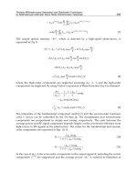
In this chapter, we aim to review the experimental details and recent applications of time-
resolved X-ray liquidography. Especially, we describe the details of the TRXL setup in
NW14A beamline at KEK, where polychromatic X-ray pulses with an energy bandwidth of
ΔE/E ~ 1 – 5% are generated by reflecting white X-ray pulses (ΔE/E = 15%) through
multilayer optics made of W/B
4
C or depth-graded Ru/C on silicon substrates. Unlike in
conventional X-ray scattering/diffraction experiments, where monochromatic X-rays are
used to achieve high structural resolution, polychromatic X-ray pulses containing more
photons than monochromatic X-ray pulses are used at the expense of the structural
resolution because a higher signal-to-noise ratio is desirable in the TRXL experiment. In
addition, we describe in detail the principle of synchronization between the laser and
synchrotron X-ray pulses, which is one of the key technical components needed for the
success of time-resolved X-ray experiments, and has been vigorously implemented in well-
established experimental techniques using synchrotron radiation, such as diffraction,
scattering, absorption and imaging. Finally, some examples of applications to various
reaction systems ranging from small molecules to proteins are described as well.
2. Experimental
2.1 Optical-pump and X-ray-scatter scheme
In a typical TRXL experiment, an ultrashort optical laser pulse initiates photochemistry of a
molecule of interest in the solution phase, and an ultrashort x-ray pulse from a synchrotron
facility, instead of an ultrashort optical pulse used in the optical pump-probe experiment, is
sent to the reacting volume to probe the structural dynamics inscribed on the time-resolved
x-ray diffraction signals as a function of reaction time. TRXL data have been collected using
an optical-pump and x-ray-probe diffractometer in the beamline ID09B at ESRF (Bourgeois
et al., 1996; Wulff et al., 1997) and the beamline NW14A of PF-AR at KEK (Nozawa et al.,
2007). The beamline 14IDB at APS also has the capability of collecting TRXL data. The
Synchrotron-Based Time-Resolved X-ray Solution Scattering (Liquidography)
789
experimental setup is schematically illustrated in Fig. 1. It comprises a closed capillary jet or
open-liquid jet to supply the solution that are pumped by laser pulses and scatter X-rays, a
pulsed laser system to excite the sample, a pulsed synchrotron source to produce ultrashort
X-ray pulses to scatter from the sample, a synchronized high-speed chopper that selects
single X-ray pulses, and an integrating charge-coupled device (CCD) area detector.
Fig. 1. Schematic drawing of the experimental setup for time-resolved X-ray liquidography.
The liquid jet is irradiated by an optical laser pulse. After a well-defined time delay (t), the
X-ray pulses generated by a synchrotron and selected by a high-speed chopper are sent to
the sample and scatter. The reference diffraction data collected at -3 ns is subtracted from
the diffraction data collected at positive time delays to extract the structural changes only.
2.2 Pulsed nature of synchrotron radiation
Synchrotron radiation is described as the radiation from charged particles accelerated at
relativistic velocities by classical relativistic electrodynamics. It provides excellent
characteristics as an X-ray source such as small divergence, short wavelength, linear or
circular polarization, etc. Synchrotron radiation has another useful feature for time-resolved
X-ray technique, short-pulsed nature, due to the periodic acceleration of charged particles in
storage ring. Electrons circulating in storage ring irradiate synchrotron radiation and lose
their energy. In order to compensate for the energy loss, a radio frequency (RF) oscillator
accelerates electrons periodically at a harmonic frequency of the revolution frequency f=c/L,
where c is the speed of light and L is the circumference of the storage ring. In order to keep
electrons circulated stably in the storage ring, electrons need to pass through the RF
oscillator at the appropriate timing, which is called the stable phase. Electrons stay and
oscillate around the stable phase as a group, which is called electron bunch. Due to this
equilibration process of the electron bunch, the length of the electron bunch is typically 15 –
45 mm (rms) that corresponds to X-ray pulse duration of 50 – 150 ps. Thus, the timing of the
synchrotron X-ray pulse is synchronized with the timing of the RF oscillator. If the laser is
externally triggered by the same RF master clock that accelerates electrons, both laser and X-
ray pulses can be stably synchronized. This is the basis of time-resolved X-ray experiments
using synchrotron radiation.
Advances in Lasers and Electro Optics
790
2.3 X-ray source characteristics and isolation of a single X-ray pulse
Synchrotron radiation is operated at MHz to GHz repetition rate depending on the bunch-
filling modes of the storage ring. In particular, time-resolved experiments at synchrotron
radiation facilities primarily require sparse bunch-filling mode of the storage ring operation
such as single-bunch or hybrid modes. In general, X-ray detectors have a relatively slow
response time and, furthermore, two-dimensional X-ray area detectors (e.g. CCD) have no
fast gating capabilities. Due to such limitation of X-ray detectors, isolation of a single X-ray
pulse from a pulse train is crucial for the success of time-resolved X-ray experiments. Since a
single pulse can be readily isolated by using a fast chopper in sparse bunch-filling mode, the
operation in the single-bunch or hybrid mode is highly desirable for time-resolved X-ray
experiments.
The 6.5 GeV PF-AR is fully operated in a single-bunch mode for about 5000 hours/year.
Electrons with a ring current of 60 mA (75.5 nC per bunch) are stored in a single electron
bunch with a life time of around 20 hours. The RF frequency and harmonic number of the
PF-AR are 508.58 MHz and 640, respectively. Therefore, the X-ray pulses are delivered at a
frequency of 794 kHz (= 508.58 MHz / 640) with a pulse duration of about 60 ps (rms). A
schematic drawing of the beam line NW14A is shown in Fig. 2.
Fig. 2. Schematic drawing of the beamline NW14A of PF-AR at KEK. The X-ray beam is
monochromized by a double-crystal monochromator and then focused using a bent-
cylindrical mirror. Higher-order harmonics are cut off by a pair of flat mirrors.
The beam line has two undulators with a period length of 20 mm (U20) and 36 mm (U36).
The U20 gives the 1st harmonic in the energy range of 13–18 keV. The energy bandwidth of
the 1st harmonic is ΔE/E = 15%, which is utilized as a narrow-bandwidth white beam for
TRXL experiments. The U36 covers an energy range of 5–20 keV with 1st, 3rd, and 5th
harmonics, and useful for X-ray spectroscopy experiments. The measured photon flux from
U36 and U20 at several gaps is shown in Fig. 3.
In order to isolate a single X-ray pulse from the sources, double X-ray choppers are
equipped at the NW14A. The first chopper, called as heat-load chopper, has an opening time
of 15 μs and is used to isolate 10-pulse train at 945 Hz (Gembicky et al., 2007). The second X-
ray chopper, made by Forschungszentrum Jülich (Lindenau et al., 2004), consists of a rotor
furnished with a narrow channel for the beam passage and isolates a single X-ray pulse
from the 10-pulse train. The Jülich chopper realizes continuous phase locking with timing
jitter less than 2 ns. The opening time of the channel at the center of the tapered aperture is
Synchrotron-Based Time-Resolved X-ray Solution Scattering (Liquidography)
791
1.64 μs. If the repetition frequency of the pump-probe experiment is lower than 945 Hz, as is
the case of using 10-Hz YAG laser system, a millisecond X-ray shutter (UNIBLITZ,
XRS1S2P0) is set up between the X-ray chopper and the sample.
Fig. 3. Measured photon flux from U20 and U36 at several gaps. The intensity was
normalized by 60 mA of the ring current and 0.318 mrad (H) x 0.053 mrad (V) beam
divergence.
2.4 Energy bandwidth of the incident X-ray beam
In order to gain maximum X-ray photon flux at 1 kHz repetition rate, energy bandwidth of
the incident X-ray is the key issue. The X-ray pulse with 3% energy bandwidth of the first
harmonics of the undulator has been used for TRXL experiments in the beamline ID09B at
ESRF (Cammarata et al., 2008; Cammarata et al., 2006; Christensen et al., 2009; Davidsson et
al., 2005; Georgiou et al., 2006; Ichiyanagi et al., 2009; Ihee, 2009; Ihee et al., 2005a; Kim et al.,
2006; Kong et al., 2008; Kong et al., 2007; Lee et al., 2008a; Lee et al., 2006; Lee et al., 2008b;
Advances in Lasers and Electro Optics
792
Plech et al., 2004; Vincent et al., 2009; Wulff et al., 2006). For example, the structural dynamics
of C
2
H
4
I
2
in methanol were studied at the ID09B beamline (Ihee et al., 2005a), and the
reaction pathways and associated transient molecular structures in solution were resolved
by the combination of theoretical calculations and global fitting analysis.
On the other hand, high-flux white X-ray at NW14A has ΔE/E = 15% energy bandwidth
when the undulator U20 is used due to relatively large electron beam emittance of PF-AR. In
order to examine the feasibility of time-resolved liquidography with such a large bandwidth
and to search for the optimal bandwidth, we simulated the Debye scattering curves for the
reaction C
2
H
4
I
2
→ C
2
H
4
I + I using (i) a 15% bandwidth with the default X-ray energy
distribution, such as the undulator spectrum at the NW14A beamline, (ii) a Gaussian
spectrum with a 5% bandwidth, (iii) a Gaussian spectrum with a 1% bandwidth, and (iv) a
Gaussian spectrum with a 0.01% energy bandwidth, as shown in Fig. 4.
Fig. 4. Debye scattering curves calculated for the model reaction C
2
H
4
I
2
→ C
2
H
4
I + I using a
0.01% (monochromatic) Gaussian X-ray energy profile (dot-dashed line), 5% Gaussian X-ray
energy profile (red solid line), 1% Gaussian X-ray energy profile (solid line), and 15% default
X-ray energy profile with a long tail (dotted line).
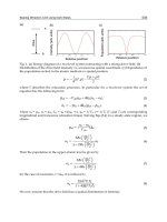
Although the photon flux of X-ray pulse increases with the energy bandwidth of the X-ray,
the simulation shows that the default X-ray spectrum that has a 15% energy bandwidth as
well as a long tail is not suitable for the time-resolved liquidography experiment owing to
deteriorated structural resolution. Especially, the long tail of the default X-ray spectrum
further blurs the scattering pattern at high scattering angles than when a symmetric
Gaussian spectrum of the same bandwidth is assumed. As a result of the asymmetric
lineshape, the X-ray spectrum with a long tail at ID09B of ESRF with a 3% bandwidth is
effectively comparable to a symmetric Gaussian spectrum with a 10% bandwidth. In
contrast, the scattering curve calculated from the Gaussian spectrum with a 5% energy
bandwidth is similar in its structural resolution to that obtained from a 0.01% energy
bandwidth (monochromatic) Gaussian spectrum. Furthermore, the total flux of the 5%
energy bandwidth X-ray beam is higher than that of the monochromatic X-ray (a 0.01%
Synchrotron-Based Time-Resolved X-ray Solution Scattering (Liquidography)
793
energy bandwidth) generated from a Si single crystal by a factor of 500. These estimations
clearly suggest that the X-ray pulses with ΔE/E of 5% is appropriate for time-resolved X-ray
liquidography experiment since it can provide a strong scattering signal without much
sacrificing the structural resolution. Thus, we reduced the bandwidth of the X-ray pulses
from the default 15% to less than the 5 % energy bandwidth.
Fig. 5. Broadband X-ray pulses were produced by multilayer optics from the undulator
spectrum. The peak energy position is controlled by changing the incident angle. The black
curve is the X-ray spectrum from the undulator U20, with a gap of 11 mm. (a) X-ray spectra
using the W/B
4
C multilayer optics. The X-ray bandwidth is about 1%. (b) X-ray spectra
using the depth-graded Ru/C multilayer optics. The X-ray bandwidth is 5%.
The multilayer optics produces X-ray pulses with a 1% to 5% energy bandwidth and allows
us to measure TRXL with the undulator at the NW14A beamline. We used two types of
multilayer optics. The first optics, made of W/B
4
C (d =27.7 Å, X-ray Company, Russia) on a
Si single crystal with a size of 50×50×5 mm
3
, provides an X-ray spectrum with a 1% energy
bandwidth, as shown in Fig. 5(a). The peak energy of the X-ray spectrum can be changed by
tilting the angle of the multilayer optics. The second multilayer optics, which is made of
depth-graded Ru/C layer (average d = 40 Å, NTT Advanced Technology, Japan), produces
a 5% energy bandwidth X-ray spectrum, as shown in Fig. 5(b). A white X-ray with a photon
flux of 1 × 10
9
photons/pulse is produced at a 1 kHz repetition rate. When multilayer optics
with 1% and 5% energy bandwidths are used at the downstream of the Jülich chopper, the
photon flux of 6 × 10
7
and 3 × 10
8
photons/pulse is obtained, respectively.
2.5 Synchronization of laser and X-ray pulses
NW14A is equipped with a 150-fs Ti:sapphire regenerative amplifier laser system (Spectra
Physics, Millenia, Tsunami, Spitfire, Empower). The Ti:sapphire laser system produces
optical pulses at 800 nm at a 945-Hz repetition rate, with the pulse energy reaching up to 800
μJ/pulse . The laser is installed in a laser booth next to the experimental hutch. An optical
parametric amplifier (Light Conversion, TOPAS-C) is also installed in the laser booth for
conversion of 800 nm light to broad spectral range from visible to mid-infrared region. The
laser beam is brought to the sample in the experimental hutch through a beam duct for the
laser. The synchronization of X-ray and laser pulses is based on the RF master clock, by
which an electron bunch is driven in the storage ring. When the X-ray experiment is
Advances in Lasers and Electro Optics
794
conducted with a 945 Hz Ti:sapphire-laser and a detector that has no gating capabilities (e.g.
CCD), an X-ray chopper is required to synchronize the X-ray and laser pulses at a 1:1 ratio.
The timing chart of the synchronization is shown in Fig. 6.
The X-ray pulse is emitted every 1.26 μs (794 kHz = 508 MHz / 640) from the PF-AR. After
the RF amplifier, the RF master clock signal of PF-AR is split into two major timing
components: one for the laser system and the other for the X-ray chopper system. In the X-
ray chopper system, the 508 MHz RF and the 794 kHz revolution signals are used as the
clock and the reference signals, respectively. A 945 Hz (794 kHz / 840) repetition frequency
of the X-ray pulses is then selected to trigger the Ti:sapphire 150-fs laser system running at
the same repetition frequency. In the laser system, the mode-locked Ti:sapphire oscillator
operating at 85 MHz (508 MHz / 6) synchronized with the X-ray pulses provides seed
pulses to the regenerative amplifier. The seed pulses trigger the regenerative amplifier
pumped by the Q-switched Nd:YLF laser at 945 Hz (85 MHz / 89600). Then, 945 Hz laser
pulses are directed to the sample position by a series of mirrors. The pulse trains of
pumping laser and probing X-ray pulses at the sample are shown together in Fig. 6. The
timing of the delay between the two pulse trains is controlled by changing the ejection
timing of the laser pulses from the regenerative amplifier using a phase shifter (Candox).
The timing of the X-ray and the laser is measured with an InGaAs metal-semiconductor-
metal (MSM) photodetector (Hamamatsu, G7096) coupled to a high-frequency preamplifier
and a 2.5 GHz digital oscilloscope (Tektronix, DPO7254). The rise time of the MSM
photodetector is typically 40 ps, which is faster than the X-ray pulse duration, and the
photodetector is set at the sample position.
Fig. 6. The timing chart of the synchronization system at NW14A when using the X-ray
chopper to synchronize 794 kHz X-ray and 945 Hz laser pulses at a 1:1 ratio. Timing settings
of the X-rays from (i) PF-AR, (ii) the X-ray chopper, (iii) the X-rays at the sample, and (iv)
the laser at the sample are shown.
Synchrotron-Based Time-Resolved X-ray Solution Scattering (Liquidography)
795
2.6 Spatial and temporal overlaps
In order to increase the signal-to-noise ratio of the TRXL data and define accurate time delay
between laser and X-ray pulses, the laser and X-ray pulses have to be overlapped at the
sample both spatially and temporally. To check the temporal overlap, we place a fast
InGaAs detector at the sample position and record the time traces of the laser and X-ray
pulses along a single time axis monitored by a 2.5 GHz digital oscilloscope. By adjusting the
laser firing time, it is possible to adjust the relative timing between the two pulses within a
few picoseconds. During an experiment, the time traces of the laser and X-ray pulses are
monitored by fast photodiodes simultaneously and non-intrusively.
The spatial overlap between X-ray and laser pulses is achieved by using a 50 μm diameter
pinhole placed at the sample position. The pinhole is located at the center of X-ray beam,
and then the laser beam is moved across the pinhole by scanning the position of the
focusing lens until it passes through the center of the pinhole. To ensure precise spatial
overlap, we monitor the intensity of scattering induced by thermal expansion in a liquid
solvent, which typically occurs in 1 μs with our beam sizes. Specifically, the ratio of
scattered intensities in the inner and outer disks of the solvent signal is monitored. Once the
sample expands, the solvent signal shifts to lower scattering angles, leading to the increase
of low-angle scattering and the decrease of high-angle scattering. Therefore, the ratio
between the inner and outer part of the solvent signal changes in proportion with the laser
excitation. The X-ray beam is typically vertically 200 μm and horizontally 250 μm. The laser
spot is of circular shape with a diameter of 300 – 400 μm.
2.7 Sample environment and data acquisition
Two different types of sample cell systems have been used: a diluted solution of 0.5~100
mM concentration or pure solvent is prepared and circulated through either a capillary or
through an open-jet sapphire nozzle. Such flow systems provide a stable liquid flow of ~0.3
mm thickness at a speed ensuring the refreshment of probe volume for every laser pulse
(typically ~3 m/s). In the capillary-based system, the solution is flowed through a quartz
capillary of 0.3 mm diameter. In the open-jet system, the capillary is removed and the
solution is passed between two flat sapphire crystals with a spacing of 0.3 mm (Kyburz),
which produces a stable naked liquid sheet directly exposed to the laser/x-ray beams. The
open-jet system producing a bare liquid jet has the advantage over the closed capillary
system in terms that the scattering background arising from the glass material of the
capillary is eliminated and thus the signal-to-noise-ratio substantially improves. The lower
background also helps to enhance the accuracy of the normalization process. In addition, the
capillary jet often encounters a problem that the excitation laser drills a hole in the capillary.
The molecules in the jet are excited by laser pulses from the femtosecond laser system
described above. To maximize the population of transients and photoproducts, the laser
pulse energy (typically 25 – 100 μJ depending on the excitation wavelength) is set to be
relatively higher than that used in typical time-resolved optical spectroscopy, and thus
multi-photon excitation often occurs. In general, one wants to follow photochemistry
induced by only one-photon absorption that the laser pulse duration of ~100 fs is stretched
to ~2 ps by introducing chirp from a pair of fused-silica prisms inserted before the sample.
To probe slow photoinduced dynamics, a nanosecond laser system is used instead of the
femtosecond laser system.
The laser beam is generally directed to the sample with a 10 degree tilt angle relative to the
X-ray beam. The scattered X-ray diffraction signal is recorded by an area detector
Advances in Lasers and Electro Optics
796
(MarCCD165, Rayonics, 2048 × 2048, ~80 μm effective pixel size) with a sample-to-detector
distance of ~45 mm. A typical exposure time is ~5 s, and, given the ~1 kHz repetition rate of
the laser/X-ray pulses, the detector receives 5 × 10
3
X-ray pulses and ~5 × 10
12
X-ray
photons per image. Diffraction data are collected for typically 10 or more time-delays (t)
from -100 ps up to 1 μs (for example, –100 ps, 0 ps, 30 ps, 100 ps, 300 ps, 1 ns, 3 ns, 10 ns, 30
ns, 100 ns, 300 ns, and 1 μs). Each time-delay is interleaved by a measurement of the
unperturbed sample (typically at –3 ns).
3. Data processing and analysis
3.1 Conversion of 2D images into 1D curves
The two-dimensional diffraction images are radially integrated into one-dimensional
intensity curve, S(q, t)
exp
, as a function of the momentum transfer q (q = (4π/
λ
)sin(2
θ
/2) where
λ is the wavelength of the X-rays, 2θ is the scattering angle, and t is the time delay). The
curves are averaged and normalized by scaling them to absolute scale of the total (elastic
and inelastic) scattering from one solution unit-cell molecule in the isosbestic point at high q
values, where the scattering is insensitive to structural changes. After normalization, the
diffraction data for the unperturbed sample measured at a negative time delay (typically at
–3 ns) is subtracted from the diffraction data collected at positive time delays to extract the
diffraction change only. The difference diffraction intensities
Δ
S(q,t) contain direct
information on the structural changes of the solute and solvent in the probed solution. The
relative laser induced diffraction signal change ΔS/S is quite small. It depends on both time
and scattering angle, and is typically less than 0.1 %. Standard deviations as a function of q
are calculated in the process of conversion from a 2D image to a 1D curve by taking into
account the distribution of the intensities at the same q value. The error of the averaged
Δ
S(q,t) can be obtained from the error propagation of standard deviations or by taking
another standard deviation from the mean value of individual difference curves. The signal-
to-noise ratio of a typical
Δ
S(q,t) depends on q and t and oscillates resembling the shape of
Δ
S(q,t) except that the negative values of
Δ
S(q,t) become positive in the plot of signal-to-
noise ratio. A typical averaged
Δ
S(q,t) from about 50 - 100 repetitions has a signal-to-noise
ratio up to 15. The signal-to-noise ratio is zero when ΔS is zero and reaches a maxima in the
peaks and valleys of
Δ
S(q,t). To magnify the oscillatory feature at high q,
Δ
S(q,t) is often
multiplied by q to yield q
Δ
S(q,t). Although q
Δ
S(q,t) contains direct information on the
structural changes, often the result in reciprocal space is not intuitive. For this reason
q
Δ
S(q,t) is transformed to real space where the changes are more readily interpretable:
positive and negative peaks means formation and depletion, respectively, of the
corresponding interatomic distance. Obtained through sine-Fourier transforms of q
Δ
S(q,t),
the difference radial distribution function (r
Δ
R(r,t)) represents the experimental atom-atom
pair distribution function during the course of the reaction.
2
2
0
1
( , ) ( , )sin( )exp( )
2
rRrt qSqt qr q dq
α
π
∞
Δ= Δ −
∫
(1)
where the constant
α
is a damping constant to account for the finite experimental q range. In
principle, the errors in the r-space can be also obtained from the same procedure as the one
described for the q-space data: The sine-Fourier transform of every single q
Δ
S(q,t) is taken
and then averaged over all r
Δ
R(r,t) curves, which defines a meaningful standard deviation.
Synchrotron-Based Time-Resolved X-ray Solution Scattering (Liquidography)
797
3.2 Data analysis
We fit the experimental difference intensities (ΔS(q,t)
exp
) for all time delays against
theoretical difference intensities (ΔS(q,t)
theory
), including the changes from three principal
components that are mutually constrained by energy conservation in the X-ray illuminated
volume: (i) the solute-only term, (ii) the solute-solvent cross term (also called as the cage
term), and (iii) the solvent-only term from hydrodynamics as in the following expression.
() ()
( ,) ( ,) ( ,) ( ,)
(,) (,)
1
() ( ) ( ) (0) () ()
theory
solute only solute solvent solvent only
solute related solvent only
kk g k
T
kk
Sqt Sqt Sqt Sqt
Sqt Sqt
ctSq Sq c S T Tt S t
R
ρ
ρρ
−− −
−−
Δ=Δ +Δ +Δ
=Δ +Δ
⎡⎤
= − +∂ ∂ Δ +∂ ∂ Δ
⎢⎥
⎣⎦
∑∑
(2)
where R is the ratio of the number of solvent molecules to that of solute molecules, k is the
index of the solute (reactants, intermediates and products), c
k
(t) the fraction of molecules in k
as a function of time t, S
k
(q) is the solute-related (the solute-only plus the cage components)
scattering intensity of species k, S
g
(q) is the scattering intensity of the reactants (k =
reactants), (∂S(q)/∂T)
ρ
is the solvent scattering change in response to a temperature rise at
constant volume, (∂S(q)/∂ρ)
T
is the response to a density change at constant temperature,
ΔT(t) and Δρ(t) are the solvent temperature and density changes as a function of time. The
equation indicates that, to calculate ΔS(q,t)
theory
, two types of basis components are needed:
time-independent functions such as S
k
(q), (∂S(q)/∂T)
ρ
and (∂S(q)/∂ρ)
T
and time-dependent
functions such as c
k
(t), ΔT(t) and Δρ(t). In the following, the steps involved in the calculation
of time-independent and time-independent basis functions are described with the
photochemistry of CHI
3
in CH
3
OH as an example. Fig. 7 presents an overall scheme for data
analysis.
Fig. 7. Schematic of the data analysis. A theoretical difference scattering curve is represented
as a sum of the three terms contributions: the solute-only term, the solute-solvent cross term,
and the solvent-only term. The discrepancy between the theory and experiment is
minimized in global fitting analysis by considering data at all positive time delays
simultaneously. See the text for details.
S
k
(q) are calculated from MD simulations combined with quantum calculations. The possible
structures of the parent molecule, the transient intermediates and the products in solution
Advances in Lasers and Electro Optics
798
are provided by fully optimizing the molecular geometry with the ab initio and/or density
functional theory (DFT) methods with solvent effects included. In case of the
photochemistry of CHI
3
in CH
3
OH, the molecular structures of all putative species such as
CHI
3
, CHI
2
, CHI
2
-I isomer, I
2
, I, and CH
3
OH are calculated. The charge on each atom of all
related species is also calculated via the natural bond orbital analysis. These structures and
the charges of all species are used as starting points for the MD simulations, where one
solute molecule is placed in a box containing 512 or more rigid solvent molecules. After MD
simulations, pair correlation functions for atom pairs (g
αβ
(r) for the atom pair α and β) are
calculated. The S
k
(q) curves are then computed by
2
0
sin( )
() () () ( () 1) 4
NN
qr
Sq f q f q N g r r dr
Vqr
αβ
αβ ααβ αβ
αβ
δπ
∞
⎛⎞
=+−
⎜⎟
⎜⎟
⎝⎠
∑
∫
(3)
where f
α
(q) is the atomic formfactor of the
α
atom, N
α
is the number of
α
atoms in the MD
simulation, δ
αβ
is Kronecker delta, and V is the volume of the MD box. Including g
αβ
(r) for
only the pairs within the solute molecule (for example, CHI
2
-I isomer has one type of C···H,
three types of C···I, three types of H···I and three types of I···I) results in the solute-only
term, which can be also described by Debye scattering of isolated solute molecules as in the
gas phase. The cage term is calculated when g
αβ
(r) for the solvent-solute cross pairs (for
example, the CHI
2
radical in CH
3
OH has C
solute
···C
solvent
, C
solute
···O, I··· C
solvent
, and I···O,
and many other pairs including H) are used in the integration. In practice, g
αβ
(r) for both
solute-only and solute-solvent cross pairs are used to yield the solute-only plus cage terms,
that is, the solute-related terms, S
k
(q). The solvent differential functions, (∂S(q)/∂T)
ρ
and
(∂S(q)/∂ρ)
T
, can be obtained either from MD simulations or determined in a separate
experiment where the pure solvent is vibrationally excited by near-infrared light
(Cammarata et al., 2006). The latter gives superior agreement than the former. In general, the
g
αβ
(r) from MD simulation for a particular atom pairs
α
and
β
can be used to calculate the
contribution from that particular atom-atom pair to the overall signal, thereby aiding the
peak assignment (for example, the atom pair of I and O gives the I···O interatomic
contribution, which is one of the major solute-solvent cross terms).
The basic strategy of the least square fits to the experimental data is to minimize the total χ
2
iteratively in a global fitting procedure, simultaneously minimizing the differences between
the experimental and theoretical curves at all positive time delays. The definition of chi-
square (χ
2
) used is as follows.
()
2
22
theory exp
t
ttq
q,t
S ( q,t ) S ( q,t )
χχ
σ
⎛⎞
Δ−Δ
⎜⎟
==
⎜⎟
⎝⎠
∑∑∑
(4)
The polychromacity of the X-ray beam has to be taken into account when a ΔS(q,t)
theory
curve
is compared with the ΔS(q,t)
exp
curve by weighting the X-ray spectrum into the ΔS(q,t)
theory
curve. A result of global fitting analysis for CHI
3
is shown in Fig. 8. The time-dependent
basis functions (c
k
(t), ΔT(t) and Δρ(t)) depend on the fitting parameters of the global fitting
analysis. A set of rate equations for a reaction kinetic model including all reasonable
candidate reaction pathways is set up to extract a reaction mechanism. As a candidate
reaction model for CHI
3
, the rate constants for dissociation (CHI
3
→ CHI
2
+ I), geminate and
non-geminate recombination (CHI
2
+ I → CHI
3
), and the non-geminate formation of
Synchrotron-Based Time-Resolved X-ray Solution Scattering (Liquidography)
799
molecular iodine (I + I → I
2
) can be considered. Integrating the rate equations provides c
k
(t)
to be used to construct the theoretical scattering signal. The ΔT(t) and Δρ(t) are
mathematically linked to c
k
(t) and to each other by energy and mass conservation and
hydrodynamics. From c
k
(t), the time-dependent heat released from solutes to the solvent,
Q(t), is calculated and used to compute ΔT(t) and Δρ(t) via thermodynamic and
hydrodynamics relations (Bratos et al., 2004).
The fitting parameters include the rate coefficients, the fraction of the excited molecules, the
fraction of the molecules undergoing structural changes, and the laser beam size. Structural
parameters such as bond lengths and angles and energy levels of chemical species can be
included as fitting parameters.
3.3 Example: Photochemistry of CHI
3
Fig. 8A shows a comparison of qΔS(q, t)
exp
and qΔS(q, t)
theory
from global fitting analysis of
TRXL data of CHI
3
in CH
3
OH, and Fig. 8B shows the corresponding rΔR(r,t)
exp
and
rΔR(r,t)
theory
. Fig. 8E summarizes the final fit values. Upon irradiation of 20 mM iodoform in
methanol, 24(±1)% of the solute molecules are excited by the laser pulse at 267 nm. Among
the excited iodoform, 28(±1)% dissociate into CHI
2
+ I within the time resolution of 100 ps,
and the remaining 72(±1)% decay into the ground state via vibrational cooling and release
their energy to the solvent. The iodine atoms recombine to form I
2
with the bimolecular rate
constant of 1.55(±0.25) × 10
10
M
-1
s
-1
. Based on these values from global fitting analysis,
chemical population changes (as shown in Fig. 8C) and the temperature and density change
of the solvent (as shown in Fig. 8D) as a function of time can be drawn. Initially, the
temperature and the pressure of the solvent increase at a constant volume due to the energy
transfer from the solute to solvent. Then, the thermal expansion occurs with a time constant
of ~50 ns, returning the sample to ambient pressure. Due to the thermal expansion, the
density of the solvent decreases by 1.2 kg/m
3
(0.15%) at 1 μs, leading to a temperature
increase of 1.02 K. After the analysis, the whole signal can be decomposed into each
component. For example, the solute-only term, the cage term, and the solvent-only term in
real space are shown in Figs. 9D, 9E, and 9F along with the assignment of the peaks in the
real space. The prominent negative peak around 3.6 Å of the solute-only term (Fig. 9D) is
due to the depletion of the I···I distance in CHI
3
and the shoulder at 2.7 Å in late time delays
is due to the formation of a new I-I bond in I
2
. Most positive and negative peaks located at
distances larger than the size of the solute molecule in Fig. 9E and 9F are related to the
solvent rearrangement due to temperature and density changes.
4. Applications
4.1 On the issue of isomer formation from CHI
3
in methanol
TRXL has been used to capture the molecular structures of intermediates and their reaction
kinetics for various photochemical processes. In the following, we present some application
examples ranging from small molecules to proteins, which illustrate the wide applicability
of TRXL.
The first example is the photochemistry of iodoform (CHI
3
). According to previous time-
resolved spectroscopic studies (Wall et al., 2003; Zheng et al., 2000), the CHI
2
radical and I
atom generated upon excitation at 267 nm geminately recombine to form iso-iodoform
within the solvent cage as the main species (quantum yield of at least 0.5) with a rise time of
7 ps and this iso-iodoform survives for up to microseconds. To investigate the possibility of
Advances in Lasers and Electro Optics
800
the isomer formation, we performed the global fitting analysis on the TRXL data with two
candidate reaction pathways ([CHI
3
→ CHI
2
+ I; simple dissociation channel] and [CHI
3
→
CHI
2
-I; isomer formation channel]). As shown in Fig. 8, the isomer channel reaction model is
not compatible with the TRXL data, but a simple dissociation channel gives good agreement
Fig. 8. Structural dynamics of the photochemistry of CHI
3
in methanol upon photolysis at
267 nm determined by TRXL. (A) Experimental difference-diffraction intensities, q
Δ
S(q, t)
(black) and theoretical curves (red) as a result of global fitting analysis. (B) Difference radial
distribution curves, r
Δ
R(r, t), corresponding to (A). (C) The population changes of the
various chemical species as a function of time delay determined from global fitting analysis.
(D) The change in the solvent density (red) and temperature (blue) determined from global
fitting analysis. (E) A reaction mechanism determined by TRXL.
Synchrotron-Based Time-Resolved X-ray Solution Scattering (Liquidography)
801
Fig. 9. Determining the major reaction channel for CHI
3
in methanol excited at 267 nm and
decomposition into three components for peak assignment. (A) q
Δ
S(q,t) for two candidate
reaction pathways, CHI
2
formation versus CHI
2
-I isomer formation, are compared.
Experimental curves with experimental errors are shown in black and theoretical curves are
in red. The CHI
2
formation channel gives superior agreement between experiment and
theory, confirming that simple dissociation is the major reaction pathway and the isomer
formation is negligible. (B) The q
Δ
S(q,10 ns) curve is decomposed into the solute-only, cage,
and solvent-only contributions. (C) The same decomposition in the real space for r
Δ
R(r,10
ns) corresponding to (B). (D) The solute-only component of r
Δ
R(r,t). (E) The cage component
of r
Δ
R(r,t). (F) The solvent-only component of r
Δ
R(r,t).
(Lee et al., 2008a). Furthermore, when both reaction models are included in the fit, the
fraction of the isomer-formation process converges to zero, confirming that the iso-iodoform
should be a minor species if it forms at all. Since the X-ray pulse width used in this study is
Advances in Lasers and Electro Optics
802
~100 ps (fwhm), the formation of iso-iodoform as a major species on time scales shorter than
our experimental time resolution cannot be ruled out. The subsequent kinetics obtained
from TRXL was detailed in the previous section (Data Analysis). It should be noted that the
data show that the formation of I
2
is dominant over other possible recombination products
such as CHI
3
(from CH
3
and I) and C
2
H
6
(from two CH
3
).
4.2 Protein folding of cytochrome c
Protein structural changes in solution have been mainly characterized by time-resolved
optical spectroscopic methods that, despite their high time resolution (<100 fs), are only
indirectly related to three-dimensional structures in space. For protein crystals, a
combination of high time resolution and structural sensitivity has become readily available
with the advent of sub-nanosecond Laue crystallography (Ihee et al., 2005b; Moffat, 2001;
Schotte et al., 2003; Srajer et al., 1996), but its applicability has been limited to a few model
systems due to the stringent prerequisites such as highly-ordered and radiation-resistant
single crystals. More importantly, crystal packing constraints might hinder biologically
relevant motions. Owing to such limitations, the time-resolved X-ray crystallography has
been applied to only reversible reactions in single crystals, and it cannot be simply used to
study irreversible reactions such as protein folding. To obtain information about protein
motions in a more natural environment, X-ray scattering and nuclear magnetic resonance
(NMR) methods have been mainly used as direct structural probes of protein structures in
solution (Grishaev et al., 2005; Schwieters et al., 2003). Due to the inverse relationship
between the interatomic distance and the scattering angle, the scattering from
macromolecules is radiated at smaller scattering angles and is typically called as small-angle
X-ray scattering (SAXS) or wide-angle X-ray scattering (WAXS) for scattering angles larger
than conventional SAXS angles. The SAXS is sensitive to overall structure, for example,
overall size and shape, of the protein, while wide-angle X-ray scattering (WAXS) gives more
detailed information on the tertiary and quaternary structure such as the fold of helices and
sheets. However, thus far, the time resolution had been limited to 160 μs at best (Akiyama et
al., 2002). As well, NMR is a powerful technique for structure determination in solution, but
it works best for small proteins and needs properly labeled samples (Kainosho et al., 2006).
More importantly, due to the nature of microwave pulses, the time resolution of protein
NMR is inherently limited to milliseconds.
In case of protein solutions, the relatively low concentration (only a few mM or less) make
TRXL measurements non-trivial, and the large molecular size of proteins (more than
thousand times larger than small molecules) complicates the structural analysis. However,
recent TRXL data from model proteins in solution have demonstrated that the medium to
large-scale dynamics of proteins is rich in information on time scales from nanoseconds to
milliseconds (Cammarata et al., 2008). TRXL methodology has been applied to human
haemoglobin (Hb), a tetrameric protein made of two identical αβ dimers, that is known to
have at least two different quaternary structures (a ligated stable “relaxed” (R) state and an
unligated stable “tense” (T) structures) in solution. The tertiary and quaternary
conformational changes of human hemoglobin triggered by laser induced ligand
dissociation have been identified using the TRXL method. A preliminary analysis by the
allosteric kinetic model gives a time scale for the R-T transition of ~1–3 μs, which is shorter
than the time scale derived with time-resolved optical spectroscopy. The optically induced
tertiary relaxation of myoglobin (Mb) and refolding of cytochrome c (Cyt-c) have been also
Synchrotron-Based Time-Resolved X-ray Solution Scattering (Liquidography)
803
studied with TRXL. As previously mentioned, the advantage of TRXL over time-resolved X-
ray protein crystallography is that it can probe irreversible reactions as illustrated with the
folding of cytochrome c as well as reversible reactions such as ligand reactions in heme
proteins.
The basic idea of protein folding is that the three-dimensional structure of proteins is mainly
determined by their amino acid sequences. Unfolded polypeptide chains use this
information to accurately and quickly fold into their native structures (Fig. 10a). The
optically triggered folding of horse heart Cyt-c has been extensively studied with
spectroscopic techniques (Chen et al., 1998; Jones et al., 1993) and also by using fast-mixing
SAXS (Akiyama et al., 2002). Cyt-c is a single domain protein similar to Mb. Unlike Hb and
Mb, Cyt-c does not usually bind external ligands such as CO since the iron atom of the heme
group is covalently coordinated to the Met-80 residue of the protein. However, if Cyt-c is
partially unfolded with a denaturing agent, it is possible to replace the Met-80 residue with
CO and the CO ligand can be optically dissociated, thereby initiating the re-folding process.
The time-dependent evolution of the TR-WAXS signal of Cyt-c after photolysis is evident,
especially in the small-angle region (Fig. 10b). As a preliminary analysis, we fitted the
observed signal as a linear combination of one pattern at the earliest time delay, 32 μs, and
Fig. 10. Application of TRXL to track the folding of cytochrome c. (a) Schematic
representation of light-induced folding of cytochrome c. (b) Time-resolved WAXS data
relative to CO-photolysis-induced folding of cytochrome c. A 200 ns laser pulse at 532 nm
was used to initiate photodissociation of the CO ligand, which in turn initiates the folding
process. Experimental data at representative time delays are shown. (c) Population of the
folded state as a function of time estimated from a linear combination of the experimental
signal at 32 μs and 0.2 s (open symbols). A simple exponential analysis yields a time
constant of about 25 ms.
Advances in Lasers and Electro Optics
804
the other at the latest time delay, 0.2 s. This simple approach reproduces the experimental
data at all times very well. The plot of the weighting factor of the late time component
against time is shown in Fig. 10c and a simple exponential analysis yields a time scale of
about 25 ms for the CO-photolysis-triggered folding.
5. Summary and future perspectives
In this chapter, we have described the principle and experimental details of TRXL technique
with recent examples of its applications. With 100-ps X-ray pulses readily available from
synchrotron radiation, TRXL has been established as a powerful tool for characterizing fast
structural transition dynamics of chemical reactions and biological processes, ranging from
small molecules to proteins in solution. In particular, the technique provides rather direct
information on transient molecular structures since scattering signals are sensitive to all
chemical species present in the sample unlike in the optical spectroscopy. Although there
still remain challenges to overcome, for example, limited structural and time resolution,
TRXL is expected to play an important role in revealing transient structural dynamics in
many other systems in solution and liquid phases, especially with the aid of next-generation
X-ray sources. At the frontier of the technical advances supporting such bright prospects of
TRXL is the advent of linac-based X-ray light sources, which can generate X-ray pulses of
femtosecond duration. They include self-amplified spontaneous emission X-ray free electron
lasers (SASE-XFEL) and energy recovery linacs (ERL) that are currently under development
will be available in the near future.
Among these novel X-ray sources, the high-gain XFEL using SASE promises to generate
highly coherent, femtosecond X-ray pulses on the order of 100 fs with a high photon flux up
to 10
13
photons per pulse. The superb time resolution of XFEL will enable us to access
reaction dynamics in femtosecond time regime, elucidating much more details of ultrafast
structural dynamics. Also, the high flux of XFEL provides the potential for single-shot
collection of the XFEL signal. On the other hand, ERL can be operated at a high repetition
rate on the order of MHz to GHz. Such high repetition rate capability of ERL will be able to
significantly improve the signal-to-noise ratio of TRXL signal since TRXL is basically a
perturbative, pump-probe type experiment. With such a high-repetition rate X-ray source,
TRXL can be implemented combined with a high-repetition rate oscillator instead of
femtosecond amplified lasers, which is commonly operated at only a kHz rate. Furthermore,
the nanometer-scale size of the X-ray beam from the ERL (typically 100-nm diameter) will
allow tight focusing of the laser beam down to the order of micrometers, enabling the
collection of signal from a small volume of sample. Since the scattering signal from the small
area will be relatively weak, low-noise and fast-gatable two-dimensional detectors are
desirable for future ERL-applied TRXL experiments. The development of pixel detectors
using silicon-on-insulator technology will pave the way for such high-performance two-
dimensional detectors.
The excellent beam characteristics of the ERL will be further extended to develop the
coherent X-ray source, for example, oscillator-type XFEL (XFEL oscillator or XFEL-O) (Kim
et al., 2008). The X-ray source generating fully coherent X-ray pulses will serve as the
ultimate X-ray light source with superb spatial and temporal coherence. Then, what kind of
potential applications can we expect once fully coherent X-ray pulses become available? For
example, by making an analogy to the ultrafast optical spectroscopy that fully takes
advantage of the temporal coherence of ultrashort optical laser pulses, one could imagine
Synchrotron-Based Time-Resolved X-ray Solution Scattering (Liquidography)
805
phase-coherent spectroscopy in the X-ray regime with controlled timing, phase, and
intensity among multiple, coherent X-ray pulses (Mukamel et al., 2009). As X-ray radiation
has the sub-nm wavelength, which corresponds to the sub-attosecond period in the time
domain, X-ray pulses offer much higher spatial and temporal resolution than achievable in
the optical regime. Thus, the development of X-ray sources that can generate coherent X-ray
pulses will revolutionize the whole X-ray science.
6. References
Akiyama, S.; Takahashi, S.; Kimura, T.; Ishimori, K.; Morishima, I.; Nishikawa, Y. & Fujisawa,
T. (2002). Conformational landscape of cytochrome c folding studied by microsecond-
resolved small-angle x-ray scattering. Proc. Nat. Acad. Sci., 99, 1329-1334.
Bourgeois, D.; Ursby, T.; Wulff, M.; Pradervand, C.; LeGrand, A.; Schildkamp, W.; Laboure,
S.; Srajer, V.; Teng, T Y.; Roth, M. & Moffat, K. (1996). Feasibility and realization of
single-pulse Laue diffraction on macromolecular crystals at ESRF. J. Synchrotron
Rad., 3, 65-74.
Bratos, S.; Mirloup, F.; Vuilleumier, R.; Wulff, M. & Plech, A. (2004). X-ray "filming" of
atomic motions in chemical reactions. Chem. Phys., 304, 245-251.
Cammarata, M.; Levantino, M.; Schotte, F.; Anfinrud, P. A.; Ewald, F.; Choi, J.; Cupane, A.;
Wulff, M. & Ihee, H. (2008). Tracking the structural dynamics of proteins in
solution using time-resolved wide-angle X-ray scattering. Nat. Methods, 5, 881-886.
Cammarata, M.; Lorenc, M.; Kim, T. K.; Lee, J. H.; Kong, Q. Y.; Pontecorvo, E.; Lo Russo, M.;
Schiro, G.; Cupane, A.; Wulff, M. & Ihee, H. (2006). Impulsive solvent heating
probed by picosecond x-ray diffraction. J. Chem. Phys., 124, 124504.
Cavalieri, A. L.; Fritz, D. M.; Lee, S. H.; Bucksbaum, P. H.; Reis, D. A.; Rudati, J.; Mills, D. M.;
Fuoss, P. H.; Stephenson, G. B.; Kao, C. C.; Siddons, D. P.; Lowney, D. P.; MacPhee, A.
G.; Weinstein, D.; Falcone, R. W.; Pahl, R.; Als-Nielsen, J.; Blome, C.; Dusterer, S.;
Ischebeck, R.; Schlarb, H.; Schulte-Schrepping, H.; Tschentscher, T.; Schneider, J.;
Hignette, O.; Sette, F.; Sokolowski-Tinten, K.; Chapman, H. N.; Lee, R. W.; Hansen, T.
N.; Synnergren, O.; Larsson, J.; Techert, S.; Sheppard, J.; Wark, J. S.; Bergh, M.;
Caleman, C.; Huldt, G.; van der Spoel, D.; Timneanu, N.; Hajdu, J.; Akre, R. A.; Bong,
E.; Emma, P.; Krejcik, P.; Arthur, J.; Brennan, S.; Gaffney, K. J.; Lindenberg, A. M.;
Luening, K. & Hastings, J. B. (2005). Clocking femtosecond x rays. Phys. Rev. Lett., 94.
Cavalleri, A.; Wall, S.; Simpson, C.; Statz, E.; Ward, D. W.; Nelson, K. A.; Rini, M. &
Schoenlein, R. W. (2006). Tracking the motion of charges in a terahertz light field by
femtosecond X-ray diffraction. Nature, 442, 664-666.
Chen, E.; Wood, M. J.; Fink, A. L. & Kliger, D. S. (1998). Time-Resolved Circular Dichroism
Studies of Protein Folding Intermediates of Cytochrome c. Biochemistry, 37, 5589-5598.
Chen, L. X.; Jager, W. J. H.; Jennings, G.; Gosztola, D. J.; Munkholm, A. & Hessler, J. P.
(2001). Capturing a Photoexcited Molecular Structure Through Time-Domain X-ray
Absorption Fine Structure. Science, 292, 262-264.
Christensen, M.; Haldrup, K.; Bechgaard, K.; Feidenhans'l, R.; Kong, Q. Y.; Cammarata, M.;
Lo Russo, M.; Wulff, M.; Harrit, N. & Nielsen, M. M. (2009). Time-Resolved X-ray
Scattering of an Electronically Excited State in Solution. Structure of the (3)A(2u)
State of Tetrakis-mu-pyrophosphitodiplatinate(II). J. Am. Chem. Soc., 131, 502-508.
Collet, E.; Lemee-Cailleau, M. H.; Buron-Le Cointe, M.; Cailleau, H.; Wulff, M.; Luty, T.;
Koshihara, S. Y.; Meyer, M.; Toupet, L.; Rabiller, P. & Techert, S. (2003). Laser-
induced ferroelectric structural order in an organic charge-transfer crystal. Science,
300, 612-615.