Radio Frequency Identification Fundamentals and Applications, Design Methods and Solutions Part 7 ppt
Bạn đang xem bản rút gọn của tài liệu. Xem và tải ngay bản đầy đủ của tài liệu tại đây (1.49 MB, 25 trang )
Radio Frequency Identification Fundamentals and Applications, Design Methods and Solutions
142
1
2
11*
22*
Lets
VV
VV
ξ
ξ
=−
=−
1, 2
ξ
ξ
- denote the components of a small disturbance from the fixed point. To see whether
the disturbance grows or decays, we need to derive differential equations for
1, 2
ξ
ξ
. Lets do
the
1,
ξ
equation first.
.
.
1
22
12 1212
1( 1 * 1, 2 * 2)
1
11
1( 1*, 2*) ( , , )
12
1( 1*, 2*) 0 int
12,21122
11
0, 1
12
fV V
ff
fV V O
VV
f V V Fixed po condition
fVfVKVK
ff
VV
V
ξξ
ξ
ξ
ξ ξξξ ξ
== + +=
∂∂
+∗ +∗ + ∗
∂∂
∀=
==∗+∗
∂∂
==
∂∂
Similarly we can write:
.
.
2
22
12 1212
2( 1 * 1, 2 * 2)
2
22
2( 1*, 2*) ( , , )
12
2( 1*, 2*) 0 int
12,21122
22
1, 2
12
fV V
ff
fV V O
VV
f V V Fixed po condition
fVfVKVK
ff
KK
VV
V
ξξ
ξ
ξ
ξ ξξξ ξ
== + +=
∂∂
+∗ +∗ + ∗
∂∂
∀=
==∗+∗
∂∂
==
∂∂
Hence the disturbance
1, 2
ξ
ξ
evolve according to
12
.
11
.
2
2
,
11
12
22
12
ff
VV
Quadratic terms
ff
VV
ξ
ξ
ξξ
ξ
ξ
∂∂
⎡⎤
⎡⎤
⎡⎤
⎢⎥
⎢⎥
∂∂
⎢⎥
=∗+
⎢⎥
⎢⎥
∂∂
⎢⎥
⎢⎥
⎢⎥
⎣⎦
⎢⎥
⎢⎥
⎣⎦
∂∂
⎣⎦
(1*,2*)
11
12
22
12
VV
Matrix
A
ff
VV
ff
VV
=
∂∂
∂∂
∂∂
∂∂
⎡⎤
⎢⎥
⎢⎥
⎢⎥
⎣⎦
RFID TAGs Coil's Dimensional Parameters Optimization As Excitable Linear Bifurcation System
143
.
11
.
2
2
11
12
22
12
Linearized system
ff
VV
ff
VV
ξ
ξ
ξ
ξ
∂∂
⎡⎤
⎡⎤
⎡
⎤
⎢⎥
⎢⎥
∂∂
⎢
⎥
=∗
⎢⎥
⎢⎥
∂∂
⎢
⎥
⎢⎥
⎢⎥
⎣
⎦
⎢⎥
⎢⎥
⎣⎦
∂∂
⎣⎦
As we move from one dimensional to two dimensional systems, still fixed points can be
created or destroyed or destabilized as parameters are varied – in our system RFID global
TAG parameters. We can describe the ways in which oscillations can be turned on or off.
The exact meaning of bifurcation is: if the phase portrait changes its topological structure as
a parameter is varied, we say that a bifurcation has occurred. Examples include changes in
the number or stability of fixed points, close orbits, or saddle connections as a parameter is
varied.
6. RFID TAG with losses as a dynamic system
RFID TAG system is not an ideal and pure solution. There are some Losses which need to be
under consideration. The RFID TAG losses can be represent first by the equivalent circuit.
The main components of RFID TAG simple equivalent circuit are Capacitor in Parallel to
Resistor and additional Parallel inductance (Antenna Unit). The RFID equivalent circuit
Under Losses consideration is as describe below:
Fig. 12.
C1loss, R1loss and L1loss need to be tuned until we get the desire and optimum dynamic
behavior of RFID system. Now, Lets investigate the RFID TAG system under those losses.
The C1, R1, L1 (Lcalc) move value displacement due to those losses: C1 >> C1+C1loss, R1
>> R1+R1loss, L1 >> L1+L1loss. We consider in all analysis that L1 is Lcalc and depend in
many parameters.
[]
0
(1,2,3,4, ) 1 2 3 4
pp
CC
Lcalc Lcalc X X X X X X X X
NN
μ
π
⎡
⎤
==∗+−+∗
⎢
⎥
⎣
⎦
Radio Frequency Identification Fundamentals and Applications, Design Methods and Solutions
144
111,222
333,444
, ,
XXXlossXXXloss
XXXlossXXXloss
then Lcalc Lcalc Lcalcloss
Lets go back to each RFID Coil Parameter and his loss value
d d dloss Aavg Aavg Aavgloss Bavg Bavg Bavgl
→+ →+
→+ →+
→+
→+ → + → +
0 0 , , ,
oss
a ao a loss bo bo boloss t t tloss w w wloss
g g gloss
→+ →+ →+ →+
→+
Now Lets sketch the X1…X4 graphs depend on Aavg and Bavg:
X1=X1(Aavg, Bavg), X2=X2(Aavg, Bavg), X3=X3(Aavg, Bavg),
X4=X4(Aavg, Bavg).
22
2* *
1*ln
*( )
Aavg Bavg
XAavg
dAavg
A
avg Bavg
⎛⎞
⎜⎟
=
⎜⎟
⎜⎟
++
⎝⎠
= X1(Aavg, Bavg) , 3D sketch
Fig. 13.
22
2* *
2*ln
*( )
Aavg Bavg
XBavg
dBavg
Aav
g
Bav
g
⎛⎞
⎜⎟
=
⎜⎟
⎜⎟
++
⎝⎠
= X2(Aavg, Bavg) , 3D sketch
RFID TAGs Coil's Dimensional Parameters Optimization As Excitable Linear Bifurcation System
145
Fig. 14.
22
32*X Aavg Bavg
A
avg Bavg
⎡⎤
⎡
⎤
=+− +
⎢⎥
⎢
⎥
⎣
⎦
⎣⎦
= X3(Aavg, Bavg) , 3D sketch
Fig. 15.
4( )/4X Aavg Bavg
=
+
= X4(Aavg, Bavg) , 3D sketch
Radio Frequency Identification Fundamentals and Applications, Design Methods and Solutions
146
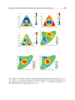
Fig. 16.
All X1, … X4 draw in one 3D coordinate system
Fig. 17.
Now lets sketch 3D diagram of Lcalc = Lcalc (Aavg, Bavg)
Fig. 18.
RFID TAGs Coil's Dimensional Parameters Optimization As Excitable Linear Bifurcation System
147
[]
1
11(0,0,,,, ,,,1,1){ }
0
1* * 1 2 3 4 *
C
p
KKabwgd tpCR
CXXXX
N
Nc
μ
π
==−
⎡
⎤
+−+
⎢
⎥
⎣
⎦
K1 = K1(Aavg, Bavg) 3D Sketch graph:
Fig. 19.
K1 is a critical function in all RFID Bifurcation system. Calculation of Aavgloss, Bavgloss
and dlossgives:
00 ( )( )
00
0() ( )
()
Aavg Aavg Aavgloss
a a loss Nc Ncloss g gloss w wloss
a a loss Nc g Nc gloss Nc w Nc wloss
Ncloss g Ncloss gloss Ncloss w Ncloss wloss
a Nc g w aloss Nc gloss wloss
Ncloss g gloss w wloss
→+ =
+−+ ∗+++=
+−∗−∗−∗−∗
−∗−∗−∗−∗=
−∗++ −∗ +
−∗+++ ()
( )
0( )( ) ()
0
Aav
g
aloss Nc
g
loss wloss
Ncloss g gloss w wloss then
Aav
g
loss a loss Nc Ncloss
g
loss wloss Ncloss
g
w
and in the same way get Bavgloss value Bavg Bavg Bav
g
loss
Bavgloss b los
=+−∗+
−∗+++
=−+ ∗+−∗+
→+
=
()( )()
2( )
2( )/
2( )
sNcNcloss
g
loss wloss Ncloss
g
w
tloss wloss
d d dloss t tloss w wloss d
tloss wloss
dloss
π
π
π
−+ ∗ + − ∗+
∗+
→+ =∗+ + + =+
∗+
=
Radio Frequency Identification Fundamentals and Applications, Design Methods and Solutions
148
Lets now describe the X1, , X4 , Lcalc internal function parameter under Losses.
[]
[]
22
111
2( )( )
ln
()
1ln
()()
2( )( )
{
()
Aavg Aavgloss
XXXloss
Aavg Aavgloss Bavg Bavgloss
Aavg Aavgloss
d dloss Aavg Aavgloss
X
Aavg Aavgloss Bavg Bavgloss
Aavg Aavgloss Bavg Bavgloss
ddloss Aa
+
→+ =
⎡ ⎤
⎢ ⎥
∗+ +
⎢ ⎥
+∗ =
⎢ ⎥
⎡⎤
+∗ + + +
⎢ ⎥
⎢⎥
⎣⎦
⎣ ⎦
+
++
∗+ +
+∗
[]
22
22
1ln
}
()()
2
2( )( )
{
()
Aavg
A
av
g
Aav
g
loss
Xloss
Aavg Aavgloss Bavg Bavgloss
vg Aavgloss
Aavg Bavg
dAavg
Aavg Bavg
Aavg Aavgloss Bavg Bavgloss
ddloss Aavg
+
⎡ ⎤
⎢ ⎥
⎢ ⎥
⎢ ⎥
⎢ ⎥
⎢ ⎥
⎢ ⎥
⎢ ⎥
⎢ ⎥
⎢ ⎥
∗
⎢ ⎥
⎢ ⎥
⎢ ⎥
⎣ ⎦
=
⎡⎤
++
++ +
⎢⎥
⎣⎦
⎡⎤
⎡⎤
∗+ +
⎢⎥
⎢⎥
⎣⎦
⎢⎥
∗∗
⎢⎥
⎣⎦
∗+ +
+∗ +
22
22
}
()()
2
Aavg
Aavg Aavgloss Bavg Bavgloss
Aavgloss
Aavg Bavg
dAavg
Aavg Bavg
⎡ ⎤
⎢ ⎥
⎢ ⎥
⎢ ⎥
⎢ ⎥
⎢ ⎥
⎢ ⎥
⎢ ⎥
⎢ ⎥
⎢ ⎥
∗
⎢ ⎥
⎢ ⎥
⎢ ⎥
⎣ ⎦
⎡⎤
++
++
⎢⎥
⎣⎦
⎡⎤
⎡⎤
∗+ +
⎢⎥
⎢⎥
⎣⎦
⎢⎥
∗∗
⎢⎥
⎣⎦
[]
[]
22
222
2( )( )
ln
()
2ln
()()
2( )( )
{
()
Bavg Bavgloss
XXXloss
Aavg Aavgloss Bavg Bavgloss
Bavg Bavgloss
d dloss Bavg Bavgloss
X
Aavg Aavgloss Bavg Bavgloss
Aavg Aavgloss Bavg Bavgloss
d dloss Ba
+
→+ =
⎡ ⎤
⎢ ⎥
∗+ +
⎢ ⎥
+∗ =
⎢ ⎥
⎡⎤
+∗ + + +
⎢ ⎥
⎢⎥
⎣⎦
⎣ ⎦
+
++
∗+ +
+∗
[]
22
22
2ln
}
()()
2
2( )( )
{
()
Bavg
Bavg Bavgloss
Xloss
Aavg Aavgloss Bavg Bavgloss
vg Bavgloss
Aavg Bavg
dBavg
Aavg Bavg
Aavg Aavgloss Bavg Bavgloss
d dloss Bavg
+
⎡ ⎤
⎢ ⎥
⎢ ⎥
⎢ ⎥
⎢ ⎥
⎢ ⎥
⎢ ⎥
⎢ ⎥
⎢ ⎥
⎢ ⎥
∗
⎢ ⎥
⎢ ⎥
⎢ ⎥
⎣ ⎦
=
⎡⎤
++
++ +
⎢⎥
⎣⎦
⎡⎤
⎡⎤
∗+ +
⎢⎥
⎢⎥
⎣⎦
⎢⎥
∗∗
⎢⎥
⎣⎦
∗+ +
+∗ +
22
22
}
()()
2
Bavg
Aavg Aavgloss Bavg Bavgloss
Bavgloss
Aavg Bavg
dBavg
Aavg Bavg
⎡ ⎤
⎢ ⎥
⎢ ⎥
⎢ ⎥
⎢ ⎥
⎢ ⎥
⎢ ⎥
⎢ ⎥
⎢ ⎥
⎢ ⎥
∗
⎢ ⎥
⎢ ⎥
⎢ ⎥
⎣ ⎦
⎡⎤
++
++
⎢⎥
⎣⎦
⎡⎤
⎡⎤
∗+ +
⎢⎥
⎢⎥
⎣⎦
⎢⎥
∗∗
⎢⎥
⎣⎦
RFID TAGs Coil's Dimensional Parameters Optimization As Excitable Linear Bifurcation System
149
22
22
22 22
22
333
2[ ]
()
2
2
()()
()()
XXXloss
Aavg Aavgloss Bavg Bavgloss
Aavg Bavg Aavgloss Bavgloss
Aavg Bavg
Aavg Aavgloss Bavg Bavgloss
Aavg Aavgloss Bavg Bavgloss
Aavg Bavg Aavg Bavg
Aavg Ba
→+ =
∗+ ++ − + =
⎡ ⎤
++ + − + +
⎢ ⎥
∗ =
⎢ ⎥
⎢ ⎥
+− +
⎣ ⎦
∗+− +
++
++
22
22
22
22
2
()
2
()
32
()
32
()()
()()
(
Aavgloss Bavgloss
Aavgloss Bavgloss
X
Aavgloss Bavgloss
Xloss
Aavg Aavgloss Bavg Bavgloss
vg
Aavg Bavg
Aavg Aavgloss Bavg Bavgloss
Aavg Bavg
Aa
⎡
⎤
+
−++
⎢
⎥
⎡⎤
+
∗ =
⎢
⎥
⎢⎥
⎣⎦
⎢
⎥
+
⎣
⎦
⎡ ⎤
+− + +
⎢ ⎥
+∗
⎢ ⎥
⎢ ⎥
+
⎣ ⎦
+−
=∗
++
++
[]
2
22
444 /4
44
4
4
)( )
Aavg Bavg Aavgloss Bavgloss
X X X loss Aavg Aavgloss Bavg Bavglos
Aavgloss Bavgloss
Xloss
vg Aavgloss Bavg Bavgloss
Aavg Bavg
⎡ ⎤
++
⎢ ⎥
⎢ ⎥
⎢ ⎥
+
⎣ ⎦
++
→+ = + + + = +
+
=
++
7. Summery
RFID TAG system can be represent as Parallel Resistor, Capacitor, and Inductance circuit.
Linear bifurcation system explain RFID TAG system behavior for any initial condition V(t)
and dV(t)/dt. RFID's Coil is a very critical element in RFID TAG
functionality. Optimization can be achieved by Coil's parameters inspection and System
bifurcation controlled by them. Spiral, Circles, and other RFID phase system behaviors can
be optimize for better RFID TAG performance and actual functionality. RFID TAG losses
also controlled for best performance and maximum efficiency.
8. References
[1] Yuri A. Kuznetsov, Elelments of Applied Bifurcation Theory. Applied Mathematical
Sciences.
[2] Jack K. Hale. Dynamics and Bifurcations. Texts in Applied Mathematics, Vol. 3
[3] Steven H. Strogatz, Nonlinear Dynamics and Chaos. Westview press
[4] John Guckenheimer, Nonlinear Oscillations, Dynamical Systems, and Bifurcations of
Vector Fields. Applied Mathematical Sciences Vol 42.
[5] Stephen Wiggins, Introduction to Applied Nonlinear Dynamical Systems and Chaos.
Text in Applied Mathematics (Hardcover).
[6] Syed A.Ahson and Mohammad Ilyas, RFID Handbook: Applications, Technology,
Security, and Privacy. CRC; 1 edition (March 18, 2008).
[7] Dr klaus Finkenzeller, RFID Handbook: Fundamentals and Applications in Contactless
Smart Cards and Identification 2
nd
edition. Wlley; 2 edition (May 23, 2003).
Radio Frequency Identification Fundamentals and Applications, Design Methods and Solutions
150
[8]Klaus Finken zeller and Rachel Waddington, RFID Handbook: Radio-Frequency
Identification Fundamentals and Applications. John wiley & Sons (January
2000).
9
Active RFID TAGs System Analysis
of Energy Consumption
As Excitable Linear Bifurcation System
Ofer Aluf
Department of Physics, Ben-Gurion University of the Negev, Be'er-Sheva,
Israel
1. Introduction
In this article, Very Critical and useful subject is discussed: Active RFID TAGs system
energy analysis as excitable linear bifurcation system. Active RFID TAGs have a built in
power supply, such as a battery, as well as electronics that perform specialized tasks. By
contrast, passive RFID TAGs do not have a power supply and must rely on the power
emitted by a RFID Reader to transmit data. Thus, if a reader is not present, the passive TAGs
cant communicate an data. Active TAGs can communicate in the absence of a reader. Active
RFID TAGs system energy consumption can be function of many variables : q(m), u(m),
z(m), t(m), tms (m), when m is the number of TAG IDs which are uniformly distributed in
the interval [0,1). It is very important to emphasis that basic Active RFID TAG, equivalent
circuit is Capacitor (Cic), Resistor (Ric), L (RFID's Coil inductance as a function of overall
Coil's parameters) all in parallel and Voltage generator Vs(t) with serial parasitic resistance.
The Voltage generator and serial parasitic resistance are in parallel to all other Active RFID
TAG's elements (Cic, Ric, and L (Coil inductance)). The Active RFID TAG equivalent circuit
can be represent as a differential equation which depending on variable parameters. The
investigation of Active RFID's differential equation based on bifurcation theory, the study of
possible changes in the structure of the orbits of a differential equation depending on
variable parameters. The article first illustrate certain observations and analyze local
bifurcations of an appropriate arbitrary scalar differential equation. Finally investigate
Active RFID TAGs system energy for the best performance using excitable bifurcation
diagram.
2. Energy aware anti collision protocol for active RFID TAGs system
Active RFID TAGs have a built in power supply, such as a battery. The major advantages of
an active RFID TAGs are: It can be read at distances of one hundred feet or more, greatly
improving the utility of the device. It may have other sensors that can use electricity for
power. The disadvantages of an active RFID TAGs are: The TAG cannot function without
battery power, which limits the lifetime of the TAG. The TAG is typically more expensive.
The TAG is physically larger, which may limit applications. The long term maintenance
costs for an active RFID tag can be greater than those of a passive TAGs if the batteries are
Radio Frequency Identification Fundamentals and Applications, Design Methods and Solutions
152
replaced. Battery outages in an active TAGs can result in expensive misreads. Active RFID
TAGs may have all or some of the following features: Longest communication range of any
TAG. The capability to perform independent monitoring and control.
The capability of initiating communications. The capabilities of performing diagnostics. The
highest data bandwidth. The active RFID TAGs may even be equipped with autonomous
networking ; the TAGs autonomously determine the best communication path. Mainly
active RFID TAGs have a built in power supply, such as battery, as well as electronics that
perform specialized tasks. By By contrast, passive RFID TAGs do not have a power supply
and must rely on the power emitted by a RFID Reader to transmit data. There is an
arbitration while reading TAGs (TAGs anti collision problem). First identify and then read
data stored in RFID TAGs.
Fig. 1.
It is very important to read TAG IDs of all. The Anti collision protocol based on two
methods: ALOHA and its variants and Binary tree search. ALOHA protocol reducing
collisions by separating TAG responds by time (probabilistic and simple). TAG ID may not
be read for a very long time. The Binary tree search protocol is deterministic in nature. Read
all TAGs by successively querying nodes at a different levels of the tree with TAG IDs
distributed on the tree based on there prefix. Guarantee that all TAGs IDs will be read
within a certain time frame. The binary tree search procedure, however, uses up a lot of
reader queries and TAG responses by relying on colliding responses of TAGs to determine
which sub tree to query next. Higher energy consumption at readers and TAGs (If they are
active TAGs). TAGs cant be assumed to be able to communicate with each other directly.
TAGs may not be able of storing states of the arbitration process in their memory. There are
three anti collision protocols: Alls include and combine ideas of a binary tree search protocol
with frame slotted ALOHA, deterministic schemes, and energy aware. The first anti
collision protocol is Multi Slotted (MS) scheme, multiple slots per query to reduce the
chances of collision among the TAG responses. The second anti collision protocol is Multi
Slotted with Selective sleep (MSS) scheme, using sleep commands to put resolved TAGs to
sleep during the arbitration process. Both MS and MSS have a probabilistic flavor, TAGs
choose a reply slot in a query frame randomly. The third anti collision protocol is Multi
Slotted with Assigned slots (MAS), assigning TAGs in each sub tree of the search tree to a
specific slot of the query frame. It’s a deterministic protocol, including the replay behavior
of TAGs. All three protocols can adjusting the frame size used per query. Maximize energy
savings at the reader by reducing collisions among TAG responses. The frame size is also
chosen based on a specified average time constraint within which all TAGs IDs must be
read. The binary search protocols are Binary Tree (BT) and Query Tree (QT). Both work by
splitting TAG IDs using queries from the reader until all TAGs are read.
Reader
Unit
TAG 0
TAG n
Interrogation
signal (query)
Active RFID TAGs System Analysis of Energy Consumption As Excitable Linear Bifurcation System
153
Binary Tree (BT) relies on TAGs remembering results of previous inquiries by the readers.
TAGs susceptible to their power supply. Query Tree (QT) protocol, is a deterministic TAG
anti collision protocol, which is memory less with TAGs requiring no additional memory
except that required to store their ID.
Fig. 2.
The approach to energy aware anti collision protocols for RFID systems is to combine the
deterministic nature of binary search algorithms along with the simplicity of frame slotted
ALOHA to reduce the number of TAG response collisions. The QT protocol relies on
colliding responses to queries that are sent to internal modes of a tree to determine the
location of TAG ID. Allow TAGs to transmit responses within a slotted time frame and thus,
try to avoid collisions with responses from other TAGs. The energy consumption at the
reader is a function of the number of queries it sends, and number of slots spent in the
receive mode. Energy consumption at an active TAG is function of the number of queries
received by the TAG and the number of responses it sends back. Neglect the energy spent in
modes other than transmit and receive for simplicity. Assumption: Time slot in which a
reader query or message is sent is equal to the duration as that of a TAG response. The
Fig. 3.
No Energy
consumption
Energy
consumption
One Frame
End of
Frame
Start of
Frame
Reader
query
Wait time
(Receive mode)
Responds (Perfix
+
TAG ID)
Query
(prefix)
Reader
TAG1
(Perfix)
TAG2
(Perfix)
TAGn
(Perfix)
TAGn+1 (no
Perfix)
TAGn+k (no
Perfix)
Radio Frequency Identification Fundamentals and Applications, Design Methods and Solutions
154
energy model of the reader is based upon a half duplex operation. Reader transmits energy
and its query for a specific period and then waits in receive mode with no more energy
transmission until end of frame. The flow chart for reader query and TAGs response
mechanism is as below:
Fig. 4.
Pulse based half duplex operation is termed as sequential (SEQ) operation.
Power required by the reader
to transmit
Power required by the reader
to receive
PRtx PRrx
Table 1.
And
No. of TAGs respond
to a specific prefix
query (reader) > 1
Start
n = 1
Reader query
(specific prefix)
TAG n, TAG n+1
… respond
YES
NO
Reader extends
the prefix by ‘0’
or ‘1’ bit and
continues the
query with this
longer prefix
TAG is resolved and
uniquely identified
n = n + 1
Active RFID TAGs System Analysis of Energy Consumption As Excitable Linear Bifurcation System
155
Power required by an active
TAG to transmit
Power required by an active
TAG to receive
PTtx PTrx
Table 2.
Fig. 5.
Reader energy consumption: q(m)*(PRtx + PRrx*F) when q(m) is the number of queries for
read m TAGs. The energy consumption of all active TAGs: q(m)*PTrx + u(m)*PTtx when
q(m) is the number of reader queires, u(m) is the number of TAG responses. For MSS
scheme (include sleep command) the reader energy consumption is
q(m) * (PRtx + PRrx * F) + z(m) * PRtx.
The total energy consumption for all active TAGs is
q(m)*PTrx + u(m)*PTtx + z(m) * PTrx,
when z(m) is the number of sleep commands issued by the reader. The average analysis of
energy consumption:
( ) .
() - .
() -
( )
() -
m average number of reader queires
m average number of TAG responses
m average number of sleep commands
issued by the reader only for MSS Scheme
m average number of time sl
q
u
z
t
−
−
−
−
−−−
.
() -
ots required
to read all TAGs
m average number of time slots required to read m TAGs
MS
t
−
m TAG IDs are uniformly distributed in the interval [0.1].
I get the expression for One active RFID TAG total energy consumption:
1
Power = * ( ) ( ) ( )
Trx Ttx Trx
TAG q m U m Z m
m
PPP
⎡
⎤
++
⎣
⎦
iii
3. Active RFID TAG equivalent circuit
Active RFID TAG can be represent as a parallel Equivalent Circuit of Capacitor and Resistor
in parallel with Supply voltage source (internal resistance).
F slots reader wait
for response
One slot for a query
from reader
Radio Frequency Identification Fundamentals and Applications, Design Methods and Solutions
156
Fig. 6.
The Active RFID TAG Antenna can be represents as Parallel inductor to the basic Active
RFID Equivalent Circuit. The simplified complete equivalent circuit of the label is as below:
Active RFID's Equivalent circuit
C1
Rs
Active RFID Antenna
L1
R1
Vs(t)
V(t)
Fig. 7.
1
4
11
11
1
0
11
1
0
2
()
(0 1)
2
11
1, 1, 0
1
1
1()
1 0
11
111
{1 } 0
11
11
1 1 ( + )
1
t
LC
LL
j
LR
t
dVs t
dt
dI dVc
LdtCIj
dt L dt
VVc
VdV VVst
CVdt
RdtL Rs
V
dV dV
CV
Rdt L dtRs
d
VC
RRs
VV
II
VV
d
t
εε
ε
=
→<<<
=
⇒= = =
== =
−
++ + =
+ + + ⎯⎯⎯⎯⎯⎯⎯→
>> ⇒ +
∑
∫
∫
ii
iiii
iii
ii ii
ii
2
2
11
+V= (t)
1
11()1
1[]0
11
S
VV
LRs
V
dV dV dVs t
CV
R dt L dt dt Rs
d
d
t
+++− =
ii
ii
ii i i
Active RFID TAG
LA
LB
An
te
nn
a
Voltage
source
Active RFID TAGs System Analysis of Energy Consumption As Excitable Linear Bifurcation System
157
1
2, V1=V
1211 11()
2, [ ] 2 1
11 1 11 1
1
001
1
111 1()
22
[]
11 1 1 1 1
dV dV
V
dt dt
dV dV dVs t
VVV
dt dt C R Rs C C L Rs C dt
dV
V
dt
dVs t
dV V
CL CR RsC RsC dt
dt
==
==−+ −+
⎛⎞
⎛⎞⎛⎞
⎜⎟
⎛⎞
⎜⎟⎜⎟
⎜⎟
=+
⎜⎟
⎜⎟⎜⎟
−−+
⎜⎟
⎜⎟⎜⎟
⎝⎠
⎜⎟
⎝⎠⎝⎠
⎝⎠
iii
ii i i
i
i
iii i
[]
0
*1234*
p
Lcalc X X X X
Nc
μ
π
⎡
⎤
=+−+
⎢
⎥
⎣
⎦
, L1 = Lcalc
22
2* *
1*ln
*( )
Aavg Bavg
XAavg
dAavg
Aavg Bavg
⎛⎞
⎜⎟
=
⎜⎟
⎜⎟
++
⎝⎠
22
2* *
2*ln
*( )
Aavg Bavg
XBavg
dBavg
Aavg Bavg
⎛⎞
⎜⎟
=
⎜⎟
⎜⎟
++
⎝⎠
22
32*XAavgBavg
Aavg Bavg
⎡
⎤
⎡
⎤
=+− +
⎢
⎥
⎢
⎥
⎣
⎦
⎣
⎦
4( )/4XAavgBavg=+ , The RFID's coil calculation inductance expression is
Definition of limits, Estimations: Track thickness t, Al and Cu coils (t > 30um). The printed
coils as high as possible. Estimation of turn exponent p is needed for inductance calculation.
Coil manufacturing technology P
Wired 1.8 – 1.9
Etched 1.75 – 1.85
Printed 1.7 – 1.8
Table 3.
Active RFID can be considered as Van der Pol’s system. Van der Pol’s equation provides an
example of an oscillator with nonlinear damping, energy being dissipated at large
amplitudes and generated at low amplitudes. Such systems typically posses limit cycles,
sustained oscillations a round a state at which energy generation and dissipation balance.
The basic Van der Pol’s equation can be written in the form:
() +X= ()XxX t
α
φβρ
+
ii i
ii i
11 1 1
1 1 ( + ) + V= (t)
11
S
VC V V
RRs L Rs
ε
>> ⇒ +
ii i i
i iii
Radio Frequency Identification Fundamentals and Applications, Design Methods and Solutions
158
111 1 1
1 ( + ) + V= (t)
11 11 1
S
VV V
C R Rs L C Rs C
ε
>> ⇒ +
ii i i
iiii
ii
111
, ( ) ( + )
11
11
1, (t) ( )
11 1
S
XV x
CRRs
Vt
LC RsC
αφ
β
ρ
→→
→→
i
ii
ii
ii
Lets define:
(t) (t) then
11 1 1
1 1 ( + ) + V= (t)
11
S
S
S
fV
VC V f
RRs L Rs
ε
=
>> ⇒ +
i
ii i
i iii
then “f “ is a “T” periodic function of the independent variable t, and
1
=
Rs
λ
The term
1
(t) (t)
S
S
fV
Rs
λ
=
i
ii
is called the forcing function.
1
00Rs
Rs
λ
→⇒ →⇒ →∞
there is no forcing and the system act as Van Der Pol Oscillator.
It is necessary to examine the trajectories (V1,V2,t) of the non-autonomous Active RFID
system in
2
x
R
R
rather than the orbits in
2
R
. Equivalently, we may consider the orbits of
the Active RFID TAGs three dimensional autonomous system.
1
2
211 1 1
[ ] 2 1 (t) (t) (t)
11 1 11 1
3
1 (V3(t)=t)
S
SS
dV
V
dt
dV
VV ffV
dt C R Rs C C L Rs C
dV
dt
=
=− + − + ∀ =
=∀
i
iii
ii i i
First examine the case of
0 1 , C1=const, then RsRs C
λ
=
⇒→∞ →∞i
The limit cycle, the isolated periodic orbit, of the unforced oscillator of Van Der Pol becomes
a cylinder; that is, topologically it is homeomorphism to
1
x
S
R . The cylinder is an invariant
manifold in the sense that any solution starting on the cylinder remains on it for all positive
time. This invariant cylinder attracts all nearby solutions. For
0
λ
=
, 0
λ
→ , →∞Rs the
Active RFID TAG invariant cylinder is filled with a family of periodic solutions. The
cylinder under the projection
22
→xR
RR
simply becomes the limit cycle. Actually Active
RFID TAGs act as periodic forcing with small amplitude, that
||
λ
small. In this case, there is
still a cylinder in
2
x
R
R
close to the invariant cylinder of the unforced oscillator. This new
cylinder is an invariant manifold of solutions of the forced equation and attracts all nearby
solutions. The flow on the invariant cylinder of the forced equation can be quite different
from the one of the unforced oscillator. In Active RFID TAG concern to Van Der Pol’s
equation we get the equation:
Active RFID TAGs System Analysis of Energy Consumption As Excitable Linear Bifurcation System
159
() +X= (t)
111 1 1
1 ( + ) + V= (t)
1111 1
111 1 1
1 ( + ) + V= (t)
1111 1
111 1
( ) 1, =(( + ) ), 1 ( 1 1 1)
1111
S
S
S
XxX f
VV f
RRsC LC RsC
VV V
RRsC LC RsC
then x L C
RRsC LC
αφ λ
ε
ε
φα
+
>> ⇒ +
>> ⇒ +
=
→≈
ii i
ii i
ii i i
ii i
ii i i
ii
ii i i
ii
ii
i
( ) 1 0 |t| > 1sec, (t) is T periodic and , are non
11 1
negative parameters. =( + ) 1, =
11
S
xf
C
RRs RsC
φαβ
αβ
=> ∀
i
i
Unforced investigation:
1
00Rs
Rs
λ
=
⇒→⇒→∞ then we return to Passive RFID TAG
since the battery has a very high serial resistance – disconnected status.
4. Active RFID TAG as a dynamic energy analysis
Active RFID equivalent circuit total TAG power is a summation of all element’s power.
1
TAG Power
N
total
i
i
p
P
=
==
∑
,
1
1
= * ( ) ( ) ( )
N
Trx Ttx Trx
i
i
qm Um Zm
m
p
PPP
=
⎡
⎤
++
⎣
⎦
∑
iii
111,
1
N
iRsC R L
i
p
pppp
=
=+++
∑
,
0
00
( , ) ( ') ' ( ') ( ') '
tt
tt
energy W t p t dt v t i t dt
t
⇒=⋅
∫∫
0
1
(,)
[]
()
N
i
total
i
dW t
d
dt dt
t
Pt
w
=
==
∑
,
2
1
2
inductor
energy L
w
I
⇒=⋅⋅
2
2
capacitor
energy
C
Q
w
⇒=
⋅
,
2
resistor
R
PI
=
⋅ ,
22
11
1,
RR RsRs
RRs
PI PI
=
⋅=⋅
2
11 1 11
11
1
2
LL LL
LL
d
energy L
dt
ww
LI P I I
⇒=⋅⋅⇒= =⋅⋅
i
2
111
1
11
21 1
CCC
C
CC
d
energy
CdtC
QQQ
ww
P
⋅
⇒= ⇒= =
⋅
i
2
11
1
11111
2
C
C
CCCC
d
energy
dt
CV
wwCVV
P
⋅
⇒= ⇒= =⋅⋅
i
1
11
1
0
1
11
t
L
LL
L
dt
LL
V
V
II
=⋅ ⋅⇒ =
∫
i
Radio Frequency Identification Fundamentals and Applications, Design Methods and Solutions
160
22
11
111
1
1
1
N
CC
RRs LL
i
i
RRsL
C
p
II II
=
⋅
=⋅+⋅+⋅⋅+
∑
i
i
2
2
11
111
1
1
[()]
N
LL
CC
i
i
L
RRs
VVst
V
p
CV V
II
=
=+ +⋅⋅+⋅⋅
−
∑
i
i
2
2
1
1
0
112 ()
[]
11
[()]
t
N
i
i
VVst V
Vdt V V
RRs Rs Rs L
Vs t
p
VC
=
⋅⋅
=
⋅+− + +⋅ +⋅⋅
∑
∫
i
1
*() () ()
Trx Ttx Trx
qm Um Zm
m
PPP
⎡
⎤
++
⎣
⎦
iii=
2
2
1
0
112 ()
[]
11
[()]
t
VVst V
Vdt V V
RRs Rs Rs L
Vs t
VC
⋅⋅
⋅
+− + +⋅ +⋅⋅
∫
i
5. Active RFID TAG fixed points and linearization
1
2
211 1 1
[]21(t)
11 1 11 1
S
dV
V
dt
dV
VVV
dt C R Rs C C L Rs C
=
=− + − +
i
iii
ii i i
Now we consider linear system:
12
(1,2), (1,2)
dV dV
f
VV gVV
dt dt
==
And suppose that
**
12
(,)
VV
is a fixed point:
** **
12 12
(,)0,
g
(,)0f
VV VV
=
=
Let
**
12
11 , 22UV UV
VV
=− =− Denote the components of a small disturbance from the
fixed point. To see whether the disturbance grows or decays, we need to derive differential
equations for U1 and U2. Lets do the U1 equation first:
11dU dV
dt dt
=
since
*
1
V
is constant.
**** 22
1212 12
11
( 1 , U2+ ) ( , ) 1 2 ( , , U1 U2)
12
ff
dU dV
fU f U U O
dt dt V V
VVVV UU
∂∂
== + = +⋅+⋅+ ⋅
∂∂
(Taylor series expansion)
To simplify the notation, we have written
1
f
V
∂
∂
and
2
f
V
∂
∂
these partial derivatives are to be
evaluated at the fixed point
**
12
(,)
VV
; thus they are numbers, not functions. Also the short
hand notation
22
12
( , , U1 U2)O
UU
⋅
denotes quadratic terms in U1 and U2. Since U1 and U2
are small, these quadratic terms are extremely small. Similarly we find
22
12
2
12(, , U1U2)
12
gg
dU
UU O
dt V V
UU
∂∂
=⋅ +⋅ + ⋅
∂∂
, Hence the disturbance (U1, U2) evolves
according to :
Active RFID TAGs System Analysis of Energy Consumption As Excitable Linear Bifurcation System
161
1
1
12
Quadratic terms
22
12
ff
dU
U
dt V V
ggdU U
dt
VV
∂∂
⎛⎞
⎛⎞
⎜⎟
⎜⎟
⎛⎞
∂∂
⎜⎟
⎜⎟
=⋅+
⎜⎟
∂∂
⎜⎟
⎜⎟
⎝⎠
⎜⎟
⎜⎟
∂∂⎝⎠
⎝⎠
.
The Matrix
**
12
(,)
A=
12
12
VV
ff
VV
gg
VV
∂∂
∂∂
∂∂
∂∂
⎛⎞
⎜⎟
⎜⎟
⎜⎟
⎝⎠
is called the Jacobian matrix at the fixed point
**
12
(, )
VV
and the Quadratic terms are tiny, its tempting to neglect them altogether.
If we do that, we obtain the linearized system.
1
1
12
22
12
ff
dU
U
dt V V
ggdU U
dt
VV
∂∂
⎛⎞
⎛⎞
⎜⎟
⎜⎟
⎛⎞
∂∂
⎜⎟
⎜⎟
=⋅
⎜⎟
∂∂
⎜⎟
⎜⎟
⎝⎠
⎜⎟
⎜⎟
∂∂⎝⎠
⎝⎠
whose
dynamic can be analyzed by the general methods.
(1,2) 2
11 1 1
(1,2) [ ] 2 1 (t)
11 1 11 1
S
fV V V
gV V V V V
CR RsC CL RsC
=
=− + − +
i
iii
ii i i
111
0, 1, , ( )
121112111
ffg g
VVVCLVCRRsC
∂∂∂ ∂
= = =− =− +
∂∂∂ ⋅∂ ii
1
01
1
111
22
[]
11 1 1 1
dU
U
dt
dU U
C L C R Rs C
dt
⎛⎞
⎛⎞
⎜⎟
⎛⎞
⎜⎟
⎜⎟
=⋅
⎜⎟
⎜⎟
−−+
⎜⎟
⎜⎟
⎝⎠
⎜⎟
⎝⎠
⎝⎠
iii
6. Active RFID TAG stability analysis based on forced Van Der Pol’s system
The basic Active RFID Forced Van Der Pol’s equation
111 1 1
1 ( + ) + V= (t)
1111 1
111 1
( ) 1, =(( + ) ), 1 ( 1 1 1)
1111
1
1
S
VV V
RRsC LC RsC
then x L C
RRsC LC
Rs C
ε
φα
β
>> ⇒ +
=
→≈
=
⋅
ii i i
ii i i
ii
ii
i
In our case
( ) 1, ( ) 0 for |V|>1 VV
φ
φ
=> and (t)
S
V
i
is T periodic and
111
(+)
11RRsC
i ,
1
1Rs C
i
are non negative parameters. It is convenient to rewrite the Active RFID forced Van Der
Pol’s equation as an autonomous system.
=t =1
d
dt
θ
θ
⇒
Radio Frequency Identification Fundamentals and Applications, Design Methods and Solutions
162
1
2
111
= Y-( + ) ( )
11
1
= -V+ ( )
11
= 1 (V, Y, )
S
V
RRsC
V
RC
x
V
Y
S
φ
θ
θ
θ
⋅
⋅
⋅
∈
i
i
i
i
i
R
() 1V
φ
= remain strictly positive as || V →∞ for unforced system
1
() 0
11
S
V
RC
θ
⋅→
⋅
i
but
1
0
11RC
≠
⋅
then
()=0
S
V
θ
i
no energy is supply to the Active RFID TAG, become
Passive RFID TAG. First we suppose that
111
1 (( + ) 1)
11RRsC
α
i
is a small parameter, so
the autonomous system is a perturbation of linear oscillator.
= Y, = -V
V
Y
i
i
which has a
phase plane filled with circular periodic orbits each of period 2
π
⋅
. Using regular
perturbation or averaging methods, we can show that precisely one of these orbits is
preserved under the perturbation. Selecting the invertible transformation:
1cos()sin()
sin( ) cos( )
2
ttV
tt
Y
ξ
ξ
−
⎛⎞ ⎛⎞⎛⎞
=⋅
⎜⎟ ⎜⎟
⎜⎟
−−
⎝⎠⎝⎠ ⎝⎠
which “freezes” the unperturbed system and the autonomous system become :
3
3
111
= -( + ) cos t [ /3-( 1 cos( ) 2 sin( ))]
11
111
= -( + ) sin t [ /3-( 1 cos( ) 2 sin( ))]
11
( 1 cos( ) 2 sin( ))
1
(1cos() 2sin())
2
tt
RRsC
tt
RRsC
tt
tt
ξξ
ξξ
ξξ
ξ
ξξ
ξ
⋅⋅ ⋅ −⋅
⋅⋅ ⋅ −⋅
⋅−⋅
⋅−⋅
i
i
i
i
this transformation is orientation reversing approximation the function
1, 2
ξ
ξ
which vary
slowly because 1, 2
ξ
ξ
are small. Integrating each function with respect to time (t) from 0 to
T=2
π
⋅ , holding 1, 2
ξ
ξ
fixed we obtain:
22
22
111
= ( + ) 1 [1 ( ) /4]/ 2
11
111
= ( + ) 2 [1 ( ) /4]/ 2
11
112
212
RRsC
RRsC
ξ
ξ
ξξξ
ξξξ
⋅⋅− +
⋅⋅− +
i
i
i
i
this system is correct at first order, but there is an error of
2
O( )
111
[( + ) ]
11RRsC
i
. In polar
coordinates, we therefore have
2
2
2
111
= ( + ) (1 ) + O( )
21 1 4
= 0 + O( )
111
[( + ) ]
11
111
[( + ) ]
11
r
RRsC
r
r
RRsC
RRsC
ϕ
⋅⋅−
i
i
i
i
i
Active RFID TAGs System Analysis of Energy Consumption As Excitable Linear Bifurcation System
163
Neglecting the
2
O( )
111
[( + ) ]
11RRsC
i
terms this system has an attracting circle of fixed
points at r = 2 reflecting the existence of a one parameter family of almost sinusoidal
solutions:
V = r(t) cos (t+ ( ))t
ϕ
⋅
with slowly varying amplitude
2
r(t) 2 O( )
111
[( + ) ]
11
RRsC
=+
i
and the phase
2
0
() O( )
111
[( + ) ]
11
t
RRsC
ϕ
ϕ
=+
i
Constant
0
ϕ
being determined by initial conditions. When the value of
111
(+)
11RRsC
i
Is not small the averaging procedure no longer works and other methods must be used.
The investigation can be done for Active RFID’s system forced Van Der Pole. Lets consider
(t) 0
S
V ≠
i
we suppose
111 1
(+) , 1
111RRsCRsC
i
i
and use the same transformation as we
use in the unforced system
(t)=0
S
V
i
. when we interest in the periodic forced response we
use the
2
π
ω
⋅
periodic transformation.
1
cos( ) sin( )
1
12
sin( ) cos( )
tt
V
Y
tt
ωω
ξ
ω
ξ
ωω
ω
⎛⎞
−⋅
⎜⎟
⎛⎞ ⎛⎞
⎜⎟
=⋅
⎜⎟ ⎜⎟
⎜⎟
⎝⎠ ⎝⎠
−−⋅
⎜⎟
⎝⎠
2
2
1
111 1
(+) ()cos( )( ) sin( ) sin( (t))
11 1
1
111 1
( + ) ( ) sin( ) ( ) cos( ) cos( (t))
11 1
1
2
S
S
Vt Vt tV
RRsC RsC
Vt Vt tV
RRsC RsC
φω ω ω
ωω
φω ω ω
ωω
ω
ξ
ω
ξ
−
=− ⋅ ⋅ ⋅− ⋅⋅ ⋅− ⋅ ⋅⋅
⋅⋅
−
=⋅⋅⋅−⋅⋅⋅−⋅⋅⋅
⋅⋅
i
i
i
i
i
i
1
1 , ( ) 1
11
φ
→=
i
V
CL
in our case.
2
2
1
111 1
(+) cos( )( ) sin( ) sin( (t))
11 1
1
111 1
(+) sin( )( ) cos( ) cos( (t))
11 1
1
2
S
S
tVt tV
RRsC RsC
tVt tV
RRsC RsC
ωωω
ωω
ωωω
ωω
ω
ξ
ω
ξ
−
=− ⋅ ⋅ − ⋅ ⋅ ⋅ − ⋅ ⋅ ⋅
⋅⋅
−
= ⋅ ⋅− ⋅⋅ ⋅− ⋅ ⋅⋅
⋅⋅
i
i
i
i
i
i
7. Summery
Active RFID TAG system can be represent as Voltage source (internal resistance) , Parallel
Resistor, Capacitor, and Inductance circuit. Linear bifurcation system explain Active RFID
TAG system behavior for any initial condition V(t) and dV(t)/dt. Active RFID's Coil is a
very critical element in Active RFID TAG functionality. Optimization can be achieved by
Coil's parameters inspection and System bifurcation controlled by them. Spiral, Circles, and
other Active RFID phase system behaviors can be optimize for better Active RFID TAG
Radio Frequency Identification Fundamentals and Applications, Design Methods and Solutions
164
performance and actual functionality. Active RFID TAG losses also controlled for best
performance and maximum efficiency.
8. References
[1] Yuri A. Kuznetsov, Elelments of Applied Bifurcation Theory. Applied Mathematical
Sciences.
[2] Jack K. Hale. Dynamics and Bifurcations. Texts in Applied Mathematics, Vol. 3
[3] Steven H. Strogatz, Nonlinear Dynamics and Chaos. Westview press
[4] John Guckenheimer, Nonlinear Oscillations, Dynamical Systems, and Bifurcations of
Vector Fields. Applied Mathematical Sciences Vol 42.
[5] Stephen Wiggins, Introduction to Applied Nonlinear Dynamical Systems and Chaos.
Text in Applied Mathematics (Hardcover).
[6] O. Aluf "RFID TAGs COIL’s Dimensional Parameters Optimization As Excitable
Linear Bifurcation Systems" (IEEE COMCAS2008 Conference, May 2008).
10
RFID Tag Antennas Mountable
on Metallic Platforms
Byunggil Yu
1
, Frances J. Harackiewicz
2
and Byungje Lee
1
1
Kwangwoon University
2
Southern Illinois University Carbondale
1
Korea
2
USA
1. Introduction
Auto identification provides information without direct contacts and human intervention
errors. Auto identification technology has become very popular in industries, such as the
service industry, inventory control, distribution logistics, security systems, transportation
and manufacturing process control. So far, the bar code technology leads the auto
identification industry, but it has several limitations such as low storage capacity, required
line-of-sight contact with the reader, and physical positioning of the scanned objects.
Recently, the radio frequency identification (RFID) has been an attractive alternative
identification technology to the barcode. The numerous potential applications of the RFID
system make ubiquitous identification possible at frequency bands of 125 KHz (LF), 13.56
MHz (HF), and 860-960 MHz (UHF). The RFID system generally consists of two basic
components: the reader and the tag, which communicate with each other by electromagnetic
waves. The reader can be a read or a read/write device that uses an antenna to send an
electromagnetic wave to wake up the tags. The tag is the data carrying device located on the
object being identified. In general, the performance of the tag seriously affects the
performance of the whole RFID system. The tag consists of the tag antenna and the
microchip. Since good connection and power transmission between the tag antenna and the
microchip directly impact on the RFID system performance, the tag antenna has to be
designed considering its operating environments or platforms.
As the use of RFID systems increases, manufacturers are pushing toward higher operating
frequencies (UHF band) for long reading range, high reading speed, capable multiple
accesses, anti-collision, and small antenna size compared to the LF or HF band RFID system.
As the operating frequency of the RFID system becomes higher, the major part of the RFID
system that mostly affects the ability to read the tag is the antenna.
There are several possible antenna types which can be used for RFID tags in this frequency
band. The dipole types of antennas such as folded dipoles and meandered dipoles are used
in many applications since they can be printed on a very thin film. However, when they are
mounted on the metallic objects, the antenna performance is seriously decreased because of
the reactance variation on the antenna impedance. Particularly, the UHF band RFID system
is a passive system where a tag does not contain its own power source. Therefore, the reader