Parallel Manipulators Towards New Applications Part 8 potx
Bạn đang xem bản rút gọn của tài liệu. Xem và tải ngay bản đầy đủ của tài liệu tại đây (4.05 MB, 30 trang )
Certified Solving and Synthesis on Modeling of the Kinematics. Problems of Gough-Type
Parallel Manipulators with an Exact Algebraic Method
203
equations having a degree twice as large as the others. Moreover, one final advantage is that
the displacement-based equations can be applied on any manipulator mobile platform.
8. Acknowledgment
I would like to thank my wife Clotilde for the time spent on rewriting and correcting the
book chapter in Word.
9. References
Alonso, M E.; Becker, E.; Roy M.F. & Woermann T. (1996) Multiplicities and idempotents
for zerodimensional systems. In Algorithms in Algebraic Geometry and Applications,
Vol. 143, Progress in Mathematics, pages 1 20.
Buchberger, B. & Loos, R. (1982) Algebraic Simplification. In Computer Algebra-Symbolic and
Algebraic Computation. SpringerVerlag, Vienna.
Buchberger B. (1985) Gröbner bases: An Algorithmic Method in Polynomial Ideal Theory. In
Multidimensional Systems Theory – Progress, Directions and Open Problems in
Multidimensional Systems, N.K. Bose (e.d.) Reidel Publishing Company, Dordrecht,
pp.184-232.
Bruyninckx, H. & DeSchutter, J. (1996) A class of fully parallel manipulators with closed-
form forward position kinematics. In Advances in Robot Kinematics, pages 411 420.
Cox, D.; Little, J. & O'Shea D. (1992) Ideals, varieties, and algorithms an introduction to
computational algebraic geometry and commutative algebra. Undergraduate texts in
mathematics. SpringerVerlag, New York.
Dedieu, J.P. & Norton, G.H. (1990) Stewart varieties: a direct algebraic method for stewart
platforms. In Proceedings of SigSam, volume 244, pages 42 59.
P. Dietmaier. (1998) The Stewart-Gough platform of general geometry can have 40 real
postures. In Advances in Robot Kinematics, pages 7 16.
Dieudonné, E.; Parrish, R. & Bardusch, R. (1972) An actuator extension transformation for a
motion simulator and an inverse transformation applying Newton-Raphson`s
method. Technical report D7067, NASA, Washington.
Didrit, O.; Petitot, M. & Walter, E. (1998) Guaranteed solution of direct kinematics problems
for general configurations of parallel manipulators. IEEE Transactions on Robotics
and Automation, Vol. 14, No. 2, pages 259 265.
Egner, S. (1996) Semi-numerical solution to 6/6-stewart-platform kinematics based on
symmetry. In Applicable Algebra in Engineering, Communication and Computing, Vol.
7, No. 6, pages 449 468.
Faugère, J C.; Gianni, P.; Lazard, D. & Mora, T. (1991) Efficient computation of zero-
dimensional Gröbner basis by change of ordering. Journal of Symbolic Computation,
Vol. 16, No. 4, pages 329 344.
Faugère, J.C. & D. Lazard. (1995) The combinatorial classes of parallel manipulators.
Mechanism and Machine Theory, Vol. 30, No. 6, pages 765 776.
Faugère, J.C. (1999) A new efficient algorithm for computing Gröbner bases (f4). J. of Pure
and Applied Algebra, Vol. 139, No. 13, pages 61 88.
Fischer, P.J. & Daniel, R.W. (1992) Real time kinematics for a 6 dof telerobotic joystick. In
Proceedings of RoManSy 9, Udine, pages 292 300.
Parallel Manipulators, Towards New Applications
204
Geddes, K.; Czapor, S. & Labahn, G. (1994) Algorithms for computer algebra. Kluwer Academic
Publishers, Nonwell.
Gosselin, C. & Angeles, J. (1988) The optimum kinematic design of a planar three dof
parallel manipulator. J. of Mechanisms, Transmissions and Automation in Design, Vol.
110, pages 35 41.
Gosselin, C.; Sefrioui, J. & Richard, M.J. (1994) On the direct kinematics of spherical three
dof parallel manipulators with coplanar platform. J. of Mechanical Design, Vol. 116,
pages 587 593, June 1994.
Griffis, M. & Duffy, J. (1989) A forward displacement analysis of a class of stewart platform.
J. of Robotic Systems, Vol. 6, No. 6, pages 703 720.
Hebsacker, M. (1998) Parallel werkzeugmaschinenkinematik. In Proceedings of IPK 98,
Internationales ParallelkinematikKolloquium, Zürich, pages 21 32.
Hunt, K.H. (1983) Structural kinematics of inparallelactuated robotarms. J. of Mechanisms,
Transmissions and Automation in Design, Vol. 105, pages 705 712.
Husty, M. (1996) An algorithm for solving the direct kinematic of Stewart-Gough type
platforms. J. of Mechanism and Machine Theory, Vol. 31, No. 4, pages 365 379, 1996.
Innocenti, C. & ParentiCastelli, V. (1990) Direct position analysis of the Stewart platform
mechanism. Mechanism and Machine Theory, Vol. 25, No. 6, pages 611 621.
Kohli, D.; Dhingra, A. & Xu, Y.X. (1992) Direct kinematics of general Stewart platforms. In
Proceedings of ASME Conference on Robotics, Spatial Mechanisms and Mechanical
Systems, Vol. 45, pages 107 112.
Lazard, D. (1992) Solving zerodimensional algebraic systems. J. of Symbolic Computation, Vol.
13, pages 117 131.
Lazard, D. (1992) Stewart platforms and Gröbner basis. In Proceedings of Advances in Robotics
Kinematics, pages 136 142, Ferrare, September 1992.
Lazard, D. (1993) On the representation of rigidbody motions and its application to
generalized platform manipulators. J. of Computational Kinematics, Vol. 1, No. 1,
pages 175 182.
Merlet, J P. (1987) Parallel manipulators, part1: Theory; design, kinematics, dynamics and
control. Technical report 646, INRIA, SophiaAntipolis.
Merlet, J P. (1994) Parallel manipulators: state of the art and perspectives. J. of Advanced
Robotics, Vol. 8, No. 6, pages 589 596, 1994.
Merlet, J P. (1997) Les Robots parallèles. Série Robotique. Hermès, Paris, second edition, traité
des nouvelles technologies edition, 1997.
Merlet, J P. (2004) Solving the forward kinematics of a Goughtype parallel manipulator
with interval analysis. The International Journal of Robotics Research, Vol. 23, No. 3,
pages 221 235.
Mourrain, B. (1993) The 40 generic positions of a parallel robot. In proceedings of ISSAC'93,
Kiev, pages 173 182.
Mourrain, B. (1993) About the rational map associated to a parallel robot. Technical report
2141, INRIA, SophiaAntipolis, November 1993.
Murray, P.; et al. (1997) A planar quaternion approach to the kinematics synthesis of a
parallel manipulator. Robotica, Vol. 15, pages 360 365.
Nanua, P.; Waldron, K. T& Murthy, V. (1990) Direct kinematic solution of a Stewart
platform. In IEEE transactions on Robotics and Automation, Vol. 6, No.4, pages 438-
444.
Certified Solving and Synthesis on Modeling of the Kinematics. Problems of Gough-Type
Parallel Manipulators with an Exact Algebraic Method
205
ParentiCastelli, V. & Innocenti, C. (1990) Forward displacement analysis of parallel
mechanisms: closedform solution of PRR3s and PPR3s structures. In Proceedings of
the ASME 21th Biennial Mechanisms Conf., Chicago, pages 263 269.
Patel, A. & Ehmann, K. (1997) Volumetric error analysis of a Stewart platform based
machine tool. In Annals of the CIRP, Vol. 46, pages 287 290.
Petuya, V.; Alonso, A.; Altazurra, O. & Hernandez, A. (2005) Resolution of the direct
position problem of the parallel kinematic platforms using the geometric iterative
method. In EEE Intern. Conf. on Robotics and Automation, Barcelona, pages 3255
3260.
Pierrot, F.; Dauchez, F. & Fournier, A. (1991) Hexa: a fast six dof fully parallel robot. In
Proceedings of the ICAR Conference, Pisa, pages 1159 1163.
Primrose, E.J.F. & Freudenstein, F. (1969) Spatial motions. part 1: Point paths of mechanisms
with four or fewer links. ASME J. of engineering for industry, Vol. 91, No. 1, pages
103 114.
Raghavan, M. (1993) The stewart platform of general geometry has 40 configurations. ASME
Trans. of Mech. Design, Vol. 115, No. 2, pages 277 282.
Raghavan, M. & Roth, B. (1995) Solving polynomial systems for the kinematic analysis and
synthesis of mechanisms and robot manipulators. Transactions of the ASME, Vol.
117, pages 71 79.
Rolland, L. (2003) Outils algébriques pour la résolution de problèmes géométriques et
l'analyse de trajectoire de robots parallèles prévus pour des applications à haute
cadence et grande précision. PhD thesis, Université Henri Poincaré, Nancy 1,
December 2003.
Rolland, L. (2005) Certified solving of the forward kinematics problem with an exact method
for the general parallel manipulator. Advanced Robotics, Vol. 19, No. 9, pages 995
1025.
Rolland, L. (2006) Synthesis on the forward kinematics problem algebraic modeling for the
planar parallel manipulator. Displacement-based equation systems. Advanced
Robotics, Vol. 20, No. 9, pages 1035 1065.
Rolland, L. (2007) Synthesis on the forward kinematics problem algebraic modeling for the
spatial parallel manipulator. Displacement-based equation systems. Advanced
Robotics, Vol. 21, No. 9, 32 pages 1071 1092.
Ronga, F. & Vust, T. (1992) Stewart platforms without computer ? In Proc. of the Intern. Conf.
of real, analytic and algebraic Geometry, Trento, pages 197 212.
Rouillier, F. (1999) Solving zerodimensional systems through the rational univariate
representation. Journal of Applicable Algebra in Engineering, Communication and
Computing, Vol. 9, NO. 5, pages 433 461.
Rouillier, F. & Zimmermann, P. (2001) Efficient isolation of a polynomial real roots.
Technical report RR4113, INRIA.
Sreenivasan, S.V. & Nanua, P. (1992) Solution of the direct position kinematics problem of
the general stewart platform using advanced polynomial continuation. In 22nd
Biennial Mechanisms Conf., Scottsdale, pages 99 106.
Sreenivasan, S.V.; Waldron, K.J. & Nanua, P. (1994) Direct displacement analysis of a 6-6
stewart platform. Mechanism and Machine Theory, Vol. 29, No. 6, pages 855 864.
Parallel Manipulators, Towards New Applications
206
Sugimoto, K. (1987) Kinematic and dynamic analysis of parallel manipulators by means of
motor algebra. J. of Mechanisms, Transmissions and Automation in Design, Vol. 109:
pages 3 7, 1987.
Tsai, L.W. & Morgan, A.P. (1984) Solving the kinematics of the most general 6 and 5 dof
manipulators by continuation methods. ASME J. of Mechanisms, Transmissions and
Automation in Design, Vol. 107, pages 189 200.
Vischer, P. (1996) Improving the accuracy of parallel robots. PhD thesis, Ecole Polytechnique
Fédérale de Lausanne.
Wampler, C.W. (1996) Forward displacement analysis of general six-in-parallel SPS
(Stewart) platform manipulators using soma coordinates. Mechanism and Machine
Theory, Vol. 31, NO. 3, pages 33 337.
10
Advanced Synthesis of the DELTA Parallel
Robot for a Specified Workspace
M.A. Laribi
1
, L. Romdhane
1*
and S. Zeghloul
2
Laboratoire de Génie Mécanique, LAB-MA-05
Ecole Nationale d’Ingénieurs de Sousse, Sousse 4003
1
,
Laboratoire de Mécanique des Solides,UMR 6610
Bd Pierre et Marie Curie, BP 30179,Futuroscope 86962 Chasseneuil
2
Tunisia
1
,
France
2
1. Introduction
Parallel manipulators have numerous advantages in comparison with serial manipulators:
Higher stiffness, and connected with that a lower mass of links, the possibility of
transporting heavier loads, and higher accuracy. The main drawback is, however, a smaller
workspace. Hence, there exists an interest for the research concerning the workspace of
manipulators.
Parallel architectures have the end-effector (platform) connected to the frame (base) through
a number of kinematic chains (legs). Their kinematic analysis is often difficult to address.
The analysis of this type of mechanisms has been the focus of much recent research. Stewart
presented his platform in 1965 [1]. Since then, several authors [2],[3] have proposed a large
variety of designs.
The interest for parallel manipulators (PM) arises from the fact that they exhibit high
stiffness in nearly all configurations and a high dynamic performance. Recently, there is a
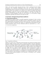
growing tendency to focus on parallel manipulators with 3 translational DOF [4, 5, 8, 9, 10,
11, 12, 13,]. In the case of the three translational parallel manipulators, the mobile platform
can only translate with respect to the base. The DELTA robot (see figure 1) is one of the most
famous translational parallel manipulators [5,6,7]. However, as most of the authors
mentioned above have pointed out, the major drawback of parallel manipulators is their
limited workspace. Gosselin [14], separated the workspace, which is a six dimensional
space, in two parts : positioning and orientation workspace. He studied only the positioning
workspace, i.e., the region of the three dimensional Cartesian space that can be attained by a
point on the top platform when its orientation is given. A number of authors have described
the workspace of a parallel mechanism by discretizing the Cartesian workspace. Concerning
the orientation workspace, Romdhane [15] was the first to address the problem of its
determination. In the case of 3-Translational DOF manipulators, the workspace is limited to
*
Corresponding author. email :
Parallel Manipulators, Towards New Applications
208
a region of the three dimensional Cartesian space that can be attained by a point on the
mobile platform.
Fig. 1: DELTA Robot (Clavel R. 1986)
A more challenging problem is designing a parallel manipulator for a given workspace. This
problem has been addressed by Boudreau and Gosselin [16,17], an algorithm has been
worked out, allowing the determination of some parameters of the parallel manipulators
using a genetic algorithm method in order to obtain a workspace as close as possible to a
prescribed one. Kosinska et al. [18] presented a method for the determination of the
parameters of a Delta-4 manipulator, where the prescribed workspace has been given in the
form of a set of points. Snyman et al. [19] propose an algorithm for designing the planar 3-
RPR manipulator parameters, for a prescribed (2-D) physically reachable output workspace.
Similarly in [20] the synthesis of 3-dof planar manipulators with prismatic joints is
performed using GA, where the architecture of a manipulator and its position and
orientation with respect to the prescribed worskpace were determined.
In this paper, the three translational DOF DELTA robot is designed to have a specified
workspace. The genetic algorithm (GA) is used to solve the optimization problem, because
of its robustness and simplicity.
This paper is organized as follows: Section 2 is devoted to the kinematic analysis of the
DELTA robot and to determine its workspace. In Section 3, we carry out the formulation of
the optimization problem using the genetic algorithm technique. Section 4 deals with the
implementation of the proposed method followed by the obtained results. Finally, Section 5
contains some conclusions.
2. Kinematic analysis and workspace of the DELTA robot
2.1 Direct and inverse geometric analyses
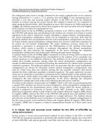
The Delta robot consists of a moving platform connected to a fixed base through three
parallel kinematic chains. Each chain contains a rotational joint activated by actuators in the
Advanced Synthesis of the DELTA Parallel Robot for a Specified Workspace
209
base platform. The motion is transmitted to the mobile platform through parallelograms
formed by links and spherical joints (See Figure 2).
We assume that all the 3 legs of the DELTA robot are identical in length. The geometric
parameters of the DELTA robot are then given as: L
1
,L
2
, r
A
, r
B
, θ
j
for j = 1, 2, 3 defined in
Figure 2, as well as ϕ
1j
, ϕ
2j
, ϕ
3j
for j = 1, 2, 3 the joint angles defining the configuration of
each leg. Let P be a point lacated on the moving plateform, the geometric model can be
written as :
(1)
Fig. 2: The DELTA robot parameters.
(2)
(3)
With j = 1, , 3
Where [ X
P
Y
P
Z
P
] are the coordinates of the point P.
In order to eliminate the passive joint variables we square and add these equations, which
yields :
(4)
Parallel Manipulators, Towards New Applications
210
Where j = 1, , 3 and r = r
A
− r
B
.
2.1.1 The direct geometric model
The direct problem is defined by (4), where the unknowns are the location of point P = [X
p
,
Y
p
,Z
p
] for a given joint angles ϕ
1j
, ϕ
2j
, ϕ
3j
(j = 1, , 3).
This equation can be put in the following form:
(5)
where,
(6)
Equation (5) represents a sphere centred in point Sj [X
j
, Y
j
,Z
j
] and with radius L
1
.
The solution of this system of equations can be represented by a point defined as the
intersection of these three spheres. In general, there are two possible solutions, which means
that, for a given leg lengths, the top platform can have two possible configurations with
respect to the base. For more details see ref [21].
2.1.2 Inverse geometric model
The inverse problem is defined by (4), where the unknowns are the joint angles ϕ
1j
, ϕ
2j
, ϕ
3j
(j = 1, 2, 3) for a given location of the point P = [X
P
, Y
P
,Z
P
] .
(7)
which can be written as:
(8)
Where,
(9)
Equation (8) can have a solution if and only if:
(10)
Advanced Synthesis of the DELTA Parallel Robot for a Specified Workspace
211
For more details on the inverse geometric model of the DELTA robot see [21,22,23].
2.2 Workspace of the DELTA robot
The workspace of the DELTA robot is defined as a region of the three-dimensional cartesian
space that can be attained by a point on the platform where the only constraints taken into
account are the ones coming from the different chains given by Equations (10). Equation (10)
can be written as:
(11)
Equation (11) in cartesian coordinates for a torus azimuthally symmetric about the y-axis
can be writen as follows :
(12)
Where, a = L
2
and b = L
1
The set of points P satisfying h
j
(X
P
, Y
P
,Z
P
) = 0 are the ones located on the boundary of this
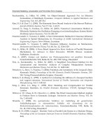
workspace. This volume is actually the result of the intersection of three tori. Each torus is
centered in point O
j
(r cosθ
j
, rsinθ
j
, 0) and with a minor radius given by L
2
and a major radius
given by L
1
. Figure 3 shows the upper halves of these tori. In the following, we will be
interested only in the upper half of the workspace.
Fig. 3: The three upper halves of the tori given by h
j
(P) = 0
Therefore, one can state that for a given point P (X
P
, Y
P
,Z
P
):
if P is inside the workspace then h
j
(P) < 0 for j = 1, 2, 3.
if P is on the boundary of the workspace then h
j
(P)
≤
0 for j = 1, 2, 3 and h
j
(P) = 0 for j = 1
or j = 2 or j = 3.
if P is outside the workspace then h
j
(P) > 0 for j = 1 or j = 2 or j = 3.
Parallel Manipulators, Towards New Applications
212
3. Dimensional synthesis of the DELTA robot for a given workspace
3.1 Formulation of the problem
The aim of this section is to develop and to solve the multidimensional, non linear
optimization problem of selecting the geometric design variables for the DELTA robot
having a specified workspace. This specified workspace has to include a desired volume in
space,W. This approach is based on the optimization of an objective function using the
genetic algorithm (GA) method.
The dimensional synthesis of the DELTA robot for a given workspace can be defined as
follows:
Given : a specified volume in space W.
Find : the smallest dimensions of the DELTA robot having a workspace that includes the
specified volume.
For example if the specified volume is a cube, then the workspace of the DELTA robot has to
include the given cube.
The optimization problem can be stated as:
min F (I)
Subject to
h
j
(I, P)
≤
0 for all the points P inside the specified volume W. (13)
x
i
∈ I
x
i
∈ [x
imin
, x
imax
]
h
j
: are the constraints applied on the system.
I : is a vector containing the independent design variables.
x
i
, is an element of the vector I, called individual in the genetic algorithm technique.
x
imin
and x
imax
are the range of variation of each design variable.
If the volume can be defined by a set of vertices P
k
(k = 1,N
pt
), then the desired volume W is
inside the workspace of the DELTA robot if:
In this work, we will take the case where W is a cube given by N
pt
= 8 points (see Figure 4).
For every workspace to be generated by a DELTA robot, the independent design variables
are:
(14)
Where H is a parameter defining how far is the specified volume from the base of the
DELTA robot (see Figure 4). This function h
j
when applied to a point can be used as a
measure of some kind of distance of this point with respect to the surface defined by h
j
= 0.
In geometry, this function is called the power of the point with respect to the surface. In the
plane, h
j
= 0 defines a curve. Annex I presents some theoretical background about the power
of a point with respect to a circle. Moreover, the function h
j
changes its sign depending on
which side of the surface the point is located. Therefore minimizing the function |h
j
(P)|, is
Advanced Synthesis of the DELTA Parallel Robot for a Specified Workspace
213
equivalent to finding the closest point to the given surface. In our case, we are looking for a
volume bounded by three surfaces, therefore one has to minimize the function f = |h
1
(I, P)|
+ |h
2
(I, P)| + |h
3
(I, P)|. Figure 5 represents a mapping , f(x, y), of the power of points at a
given height z
0
= 1 as a function of x and y for a given design vector I = [1.9, 1.2, 0.9, 1].
Fig. 4: The scheme of the prescribed workspace.
The function f is given by:
One can notice that the minimum value of f is obtained when the point is located on the
boundary of the workspace (see Figure 5).
Our objective is to find the smallest set of parameters, given by I = [L
1
,L
2
, r,H] that can yield
a DELTA robot having a workspace that includes the given volume in space W.
The methodology followed to solve this problem is based on minimizing the power of the
vertices, defining the given volume, and to ensure that all these vertices have a negative
power, i.e., they are inside the workspace of the DELTA robot. This minimization problem
will be solved using the GA method.
It is worth noting that this procedure is valid for any convex volume defined by a set of
vertices.
3.2 GA optimization
The GA is a stochastic global search method that mimics the metaphor of natural biological
evolution [24]. GAs operate on a population of potential solutions applying the principle of
survival of the fittest to produce better and better approximations to a solution. At each
generation, a new set of approximations is created by the process of selecting individuals
according to their level of fitness in the problem domain and breeding them together using
operators borrowed from natural genetics. This process leads to the evolution of
populations of individuals that are better suited to their environment than the individuals
that they were created from, just as in natural adaptation. The GA differs substantially from
more traditional search and optimization methods. The four most significant differences are:
• GAs search a population of points in parallel, not a single point.
Parallel Manipulators, Towards New Applications
214
• GAs do not require derivative information or other auxiliary knowledge; only the
objective function and corresponding fitness levels influence the directions of search.
• GAs use probabilistic transition rules, not deterministic ones.
• A number of potential solutions are obtained for a given problem and the choice of final
solution can be made, if necessary, by the user.
Fig. 5: Graphical representation of the power of a point F(X, Y ).
In most applications involving GAs, binary coding is used. However,Wright [32] showed
that real-coded GAs have a better performance than binary-coded GAs [25,26,27,28,29]. A
real-coded GA is used in this work. The description of the operations necessary for this type
of code are presented by Figure 6, more details can be found in [30]. The parameters used in
this work are shown in Table 1.
A penalty function method is used to handle the constraints and to ensure that the fitness of
any feasible solution is better than infeasible ones.
The fitness function is constructed as:
(15)
Advanced Synthesis of the DELTA Parallel Robot for a Specified Workspace
215
Where F
1
is a penality function defined as follows:
(16)
where
(17)
Where, cf is a large positive constant.
Fig. 6: Genetic algorithm flowchart.
Tab. 1: Parameters used for the genetic algorithm.
F
1
= 0 means that all the vertices defining the volume W are contained within the workspace
of the DELTA robot. In this case, the fitness F
2
is given by
Parallel Manipulators, Towards New Applications
216
In the case when F
1
≠ 0, i.e., at least one of the vertices is outside the workspace, F
2
is set to
zero (F
2
= 0).
4. Results
All the results, presented in this section, are obtained on a Pentium M processor of 1500 Mhz
and the programs are developed under MATLAB . The calculation time, necessary for
obtaining the optimum solution, is estimated at about 4s.
4.1 Example 1
In this example, the dimensions of the DELTA robot are to be determined to get the smallest
workspace capable of containing a volume W, given by a cube with a side 2a = 2 (Figure 4).
The bounding interval for each one of the design variables is presented in Table 2:
Tab. 2: The bounding interal for design variables
The optimal solution obtained by the GA for this example is presented in Table 3:
Tab. 3: The optimal dimension of DELTA robot (example 1)
Figure 7 presents a mapping, f, of the power of points at a given height equal to 1.01 as a
function of x and y for the optimal solution. A 3D representation of the platform and the
corresponding workspace along with the desired volumeW, is shown on Figure 8. Figure 9
presents horizontal slices of the workspace at the lower and upper faces of the cube. One can
notice that the upper vertices of the cube are exactly located on the boundary of the
workspace; which means that the robot has to be in an extreme position (on the boundary of
the workspace) to be able to reach these points. To avoid this problem, we propose to design
a robot having a slightly bigger workspace defining this way a safety region. The following
example illustrates this problem.
4.2 Example 2
In this second example, a distance is kept between the workspace of the DELTA robot and
the desired volume. To have this safety region, we used the fact that a safety distance can be
kept, during the optimization, between each vertex and the surface defining the boundary of
the workspace. This safety distance can be translated in terms of the power of the point,
which means that, during the optimization, a lower bound is set on the powers of all points.
This lower bound ensures that in the final solution no point can be on the surface defining
the boundary of the workspace, i.e., the power is zero in that case, but rather on a surface
parallel to the boundary of the workspace. The distance between these two surfaces is
defined as the safety distance.
Advanced Synthesis of the DELTA Parallel Robot for a Specified Workspace
217
Fig. 7: Graphical representation of the power of a point F(X, Y ) (example 1).
Fig. 8: The Optimal DELTA robot for example 1.
Parallel Manipulators, Towards New Applications
218
In our case, the workspace is the intersection of three tori, each with L
1
as a major radius and
L
2
as the minor radius. Therefore, the three corresponding tori, each with a major radius L
1
and a minor radius L
2
− e, define a more restrictive volume of the workspace. The
intersection of the smaller tori is now the bounding volume within which the desired
volume W has to be located. In this case, we took e = 0.1L
2
.
Fig. 9: Two slices of the workspace at the top and bottom of the cube.
The new optimal solution found for the DELTA robot is given by Table 4. One can notice
that L
1
and r decreased, whereas L
2
increased, compared to the previous example. The height
of the cube with respect to the base, H, stayed almost the same.
Figure 10 shows slices at the upper and lower faces of the cube of the workspace and the
corresponding safety region. Figure 11 shows two cuts of the workspace with the cube
inside it. One can notice that the vertices of the cube are kept at a minimum distance given
by the safety distance e.
A 3D representation of the platform and the corresponding workspace along with the
desired volume W, is shown on Figure 12. One can notice that all the points of the cube can
be reached by the platform without reaching an extreme configuration as it was the case, in
the previous example.
Tab. 4: The optimal dimension of DELTA robot with safety zone (example 2)
Fig. 10: Two slices of the workspace at the top and bottom of the cube with a safety zone.
Advanced Synthesis of the DELTA Parallel Robot for a Specified Workspace
219
Fig. 11: Different slices of the Workspace.
Fig. 12: The Optimal DELTA robot.
4.3 Example 3
In this example we propose an hexagonal prism as a prescribed workspace, given by N
pt
=
13 points (see figure 13). The dimensions of the DELTA robot are to be determined to get the
smallest workspace capable of containing a volume W, given by an hexagonal prism with a
side b = 1. The bounding interval for each one of the design variables is presented in Table 5:
Parallel Manipulators, Towards New Applications
220
Tab. 5: The bounding interval for design variables
Figure 14 and 15 present a mapping, f, of the power of a point at a given height equal to 1.67
as a function of x and y for the optimal solution obtained by the GA presented in Table 6.
A 3D representation of the platform and the corresponding workspace along with the
desired volume W, are shown on Figure 16.
Fig. 13: The scheme of an hexagonal prism prescribed workspace.
Fig. 14: Graphical representation of the power of a point F(X, Y ) for an hexagonal prism
prescribed workspace.
Advanced Synthesis of the DELTA Parallel Robot for a Specified Workspace
221
Tab. 6: The optimal dimension of the DELTA robot with a hexagonal prism as a prescribed
workspace
Fig. 15: Graphical representation of the power of a point F(X, Y ) for a hexagonal prism as a
prescribed workspace.
Fig. 16: The Optimal DELTA robot for an hexagonal prism as a prescribed workspace.
5. Conclusion
An optimal dimensional synthesis method suited for the DELTA robot was presente in this
paper. An objective function, used the concept of the power of a point,which reflects the
position of a point with respect to the boundary of the workspace. This objective function
allowed us to find the robot having the smallest workspace containing a prespecified region.
Parallel Manipulators, Towards New Applications
222
The genetic algorithm method was used.The prescribed region was chosen as a cube then as
an hexagonal prism. The obtained solution yields a workspace where some of the vertices of
the cube or the hexagonal prism are located on the boundary of the workspace. To reach
these points the DELTA robot has to get into extreme configurations. To avoid this problem,
we introduced a safety distance allowing us to have all the prespecified region inside the
workspace. The concept of the power of a point along with the GA method turned out to be
an effective and easy tool to solve the problem of designing a DELTA robot for a specified
workspace. This method can also be applied, in a similar manner, to any convex prismatoid
prespecified region of the workspace.
6. References
D. Stewart,1965, ”A platform with 6 degrees of freedom”, Proc. of the Institution of
mechanical engineers, Vol. 180 (Part 1, 15),pp. 371-386, 1965.
E. F. Fichter,1986, ”A Stewart platform based manipulator: general theory and practical
construction”,International Journalof Robotic Resarch, Vol. 5, pp. 157-182.
Griffis, M., and Duffy, J., ”A Forward Displacement Analysis of a Class of Stewart
Platforms,” Trans. ASME Journal of Mechanisms, Transmissions, and A utomation
in Design, Vol. 6, No. 6, June 1989, pp. 703-720.
Affi Z., Romdhane L. and Maalej A., 2004. Dimensional synthesis of a 3-translational-DOF
in-parallel manipulator for a desired workspace. European Journal of Mechanics -
A/Solids, Vol 23, Issue 2, pp 311-324.
Clavel, R. 1986. Une nouvelle structure de manipulation parallèle pour la robotique légère.
R.A.I.R.O. APII, Vol 23, N° 6.
Vischer P. and Clavel R. 1998,”Kinematic Calibration of the Parallel Delta Robot”, Robotica,
16, pp. 207-218.
M. Stock and K. Miller 2003, ”Optimal Design of Spatial Parallel Manipulators: Application
to linear Delta Robot”, ASME Journal of Mechanical Design, Vol. 125, pp 292–301.
Hervé J. M. 1995, “Design of Parallel Manipulators via Displacement Group”, Proceedings
of the 9th World Congress on the Theory of Machines and Mechanisms. pp. 2079-
2082.
Hervé, J. M., Sparacino F. 1991. Structural synthesis of parallel robots generating spatial
translation. 5th Int.Conf. On Adv. Robotics, IEEE n°91TH0367-4, Vol. 1, pp 808-813.
Romdhane, L. 1999, Design and analysis of a hybrid serial-parallel manipulator. Mechanism
and Machine Theory, Vol. 34, Issue 7, pp 1037-1055.
Romdhane, L., Affi Z., Fayet M., 2002. Design and singularity analysis of a 3 translational-
DOF in-parallel manipulator. ASME Journal of Mechanical Design, Vol. 124, pp
419–426.
A. Tremblain and L. Baron 1999, ”Geomatrical synthesis of parallel manipulators of star-like
topology with a geometric algorithm”, IEEE International Conference on Robotics
and Automation, Detroit, MI.
Tsai L-W 1996,“Kinematics of three-dof platform with three extensible limbs” In J. Lenarcic
V. Parenti-Castelli, editor, Recent Advances in Robot Kinematics, pp 401 410,
Kluwer.
C. Gosselin,1990, ”Determination of the workspace of 6-dof parallel manipulators”, ASME
Journal of Mechanical Design, Vol. 112, pp. 331-336.
Advanced Synthesis of the DELTA Parallel Robot for a Specified Workspace
223
L. Romdhane,1994, ”Orientation workspace of fully parallel mechanisms”, Eur. J. of
Mechanics Vol. 13, pp. 541-553.
R. Boudreau and C. M. Gosselin 1999, ”The synthesis of planar parallel manipulators with a
genetic algorithm”, ASME Journal of Mechanical Design, Vol 121, pp 533-537.
R. Boudreau and C. M. Gosselin 2001, ”La synthèse d’une plate forme de Gough-Stewart
pour un espace de travail atteignable prescrit”, Mech. Mach. Theory 36 (2001) 327-
342.
Kosinska, A, Galicki, M. and Kedzior, K. 2003,”Design and optimization of parameters of
Delta-4 Parallel Manipulator for a Given Workspace”, Journal of Robotic Systems
20 (9), pp 539-548.
J. A. Snyman and A. M. Hay 2005, ”Optimal synthesis for a continuos prescribed dexterity
interval of 3-DOF parallel planar manipulator for different prescribed output
workspaces”, Proceeding of CK2005, 12th International Workshop on
Computational Kinematics Cassino May 4-6.
M. Gallant and R. Boudreau 2002, ”The synthesis of planar parammel manipulators with
prismatic joints for an optimal, singularity-free workspace”, Journal of Robotic
Systems 19 (1), pp 13-24.
F. Pierrot, C. Reynau and A. Fourier 1990, ”DELTA : a simple and efficient parallel robot”,
Robotica Vol. 8, pp 105-109.
Goudali, A. 1995. Contribution à l’étude d’un nouveau robot Parallèle 2- Delta à six degrés
de liberté avec découplage. Thèse de doctorat Génie Mécanique L.M.S. Poitiers.
France.
J.P. Lallemand, A. Goudali and S. Zeghloul, ”The 6 - D.o.f. 2 - Delta parallel robot” ,
Robotica Journal, Vol. 15, pp 407-416, 1997.
Goldberg, D.E., 1994, Genetic Algorithms in Search, Optimization, and Machine Learning,
Addison-Wesley Publishing, Reading, MA.
Chipperfield A., Fleming P., Pohlheim H. and Fonseca C. 1994, ”Genetic
AlgorithmTOOLBOX user’s Guide” Department of automatic control and systems
engineering university of Sheffield version (v 1.2)
J.A. Lozano , P. Larranaga, M. Grana, F.X. Albizuri 1999, Genetic algorithms: bridging the
convergence gap, Theoretical Computer Science Vol. 229, pp 11-22.
R. Chelouah, P. Siarry 2000, A continuous genetic algorithm designed for the global
optimization of multimodal functions, Journal of Heuristics Vol. 6, pp. 191-213.
Schmitt L. M. 2001, Fundamental Study Theory of genetic algorithms, Theoretical Computer
science n°259 pp 1-61.
Laine, R., Zeghloul, S., Ramirez, G., 2002, A Method based on a Genetic Algorithm for the
Optimal Design of Serial Manipulators, Int. Symp. Rob. and Aut., pp. 15-20, Toluca,
Mexique.
M.A. Laribi, A. Mlika, L. Romdhane and S. Zeghloul, 2004,”A Combined Genetic Algorithm-
Fuzzy Logic Method (GA-FL) in Mechanisms Synthesis”, Mech. Mach. Theory 39,
pp. 717-735.
Coxeter, H. S. M.1969, ”Introduction to Geometry”, 2nd ed. New York: Wiley.
Alden H. Wright, 1991,”Genetic algorithms for real parameter optimization, Foundations of
Genetic Algorithms”, (edited by Gregory J. E. Rawlins), Morgan Kaufman, pp. 205-
218.
Steiner, J., 1826 ,”Einige geometrische Betrachtungen.” J. reine angew. Math. 1, pp. 161-184.
Parallel Manipulators, Towards New Applications
224
A Appendix
The power of a fixed point A (see Figure 17) with respect to a circle of radius r and center O
is defined by the product
Where, P and Q are the intersections of a line through A with the circle. The term ”power”
was first used in this way by Jacob Steiner [33,31]. f (A) is independent of the choice of the
line APQ.
Now consider a point A (see Figure 17) not necessarily on the circumference of the circle. If d
= OA is the distance between A and the circle’s center O with equation f (x, y) = x
2
+ y
2
− r
2
=
0, then the power of the point A relative to the circle is givn by :
Fig. 17: The power of the point.
If A is outside the circle, its power is positive and it is equal to the square of the length of the
segment AQ from A to the tangent Q to the circle through A,
If A is inside the circle, then the power is negative.
11
Size-adapted Parallel and Hybrid Parallel
Robots for Sensor Guided Micro Assembly
Kerstin Schöttler, Annika Raatz and Jürgen Hesselbach
Technische Universität Braunschweig, Institute of Machine Tools and Production
Technology (IWF), Langer Kamp 19 B, D-38106 Braunschweig
Germany
1. Introduction
Miniaturized products and components are part of today’s daily life. The comfort and
security of automobiles is increased by use of micro sensors and actuators. Electronic
devices, such as mobile phones and MP3-players, have reached very small sizes and
miniaturized medical instruments facilitate endoscopic surgery.
Due to the advantages of micro technological solutions, such as small dimensions and low
weight, Micro Systems Technology (MST) is worldwide considered a key technology of the
21
st
century. The new NEXUS market analysis forecasts a yearly growth of the world
markets of 16% for products based on MST (Wicht & Bouchaud, 2005).
Miniaturization and simultaneous function integration are leading to increased
requirements regarding production technology as a result of scaling effects, technical and
assembly related problems (van Brussel et al., 2000). For MST products, micro assembly
uncertainties in the range of a few micrometers or even less than one micrometer are
required.
1.1 Approaches to meet the requirements for micro assembly
At present industrial applications for micro assembly predominantly incorporate systems
which were originally developed for 2D chip assembly in semi-conductor back-end
production. They can be classified into three groups according to their attainable assembly
uncertainty. Most of the positioning units of the first class are pick-and-place machines
based on Cartesian axes with uncertainties between 30 µm and 60 μm at 3σ. The second
group, die-bonding machines, reaches pick-and-place uncertainties of 10 µm to 12 μm at 3σ
by means of high-precision linear drives, high-resolution camera systems as well as systems
for controlling and compensating for influences caused by changing temperatures. Ultra-
precision die-bonders form the third class. They can be regarded as special machines for
specific applications which were developed for the assembly of micro-optical components,
optical fibres and especially for flip-chip assembly. They reach assembly or pick-and-place
uncertainties of about 1 μm at 3σ. These low uncertainties can only be achieved with the
help of special camera systems and positioning strategies. At present, these assembly
uncertainties are always tied to a highly customized design of the assembly system adjusted
Parallel Manipulators, Towards New Applications
226
to the requirements of the products. This way the assembly uncertainties described are
reached at the expense of a very low flexibility (Raatz & Hesselbach, 2007).
For the design of micro assembly systems it is necessary to gain a high product flexibility of
the assembly units. Solutions that provide enough flexibility to reconfigure the system
design need to be found. Here, modularity is the key when striving for high flexibility of the
number of quantities, product variants and manufacturing base. The precision robot
represents the central component within the assembly system. Some fundamental
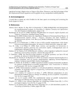
techniques to lower the uncertainty of the precision robot and the assembly system are
choosing an adequate kinematic structure, developing size adapted handling devices,
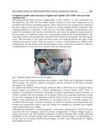
integrating ultra-precision machine elements and/or using sensor guidance (Fig. 1).
Precise peripherie
(gripper, feeder)
Ultra-precision
machine elements
Sensor
guidance
Increased accuracy
Size adapted
handling devices
Kinematic
structure
Precision
robot
Assembly
system
Fig. 1. Approaches to meet the requirements of accuracy (Raatz & Hesselbach, 2007)
1.2 Kinematic structures
Robots can be classified in terms of their kinematic structure into serial, parallel and hybrid
(serial/parallel) robots. Most industrial robots are based on a serial structure between the
frame and the working platform. All joints of open kinematic chains have a single degree of
freedom (DOF) and are active, i.e. they are actuated. The serial structure offers in principle a
large workspace in relation to the size of the robot as well as a high orientation range. The
relatively large moved masses are a disadvantage of serial structures regarding the
dynamics and accuracies of the robot, since each drive must be moved along with the entire
kinematic chain. In micro assembly, large moved masses lead to massive construction of the
frames and the robot links related to the size of the assembled parts.
Parallel robots are based on closed kinematic chains, i.e. they have several guiding chains
between the base frame and the working platform, which provide a high structural stiffness.
It is possible to install all drives in a fixed frame or at least to locate them nearby the frame,
which results in low inertia. Drive positioning errors or tolerances in the legs are not
necessarily added. Usually they partially compensate each other and only affect the
positioning uncertainty of the end effector to a small extent.
Parallel robots are well suited for highly precise handling operations, due to their high
structural stiffness with low moved masses at the same time. Compared to serial robots, the
miniaturization of a parallel robot is much easier because all joints are passive. In addition
the passive joints offer the potential for integrating flexure hinges as ultra-precision machine
elements. The small workspace compared to the robot dimensions does not become severe
in micro assembly tasks due to the size of the objects.
Combining a parallel structure with a serial structure the limited and position dependent
mobility of the end effector can be overcome. For example by integrating a serial rotational
axis into the working platform of a parallel robot, the end effector can be very well oriented.
Size-adapted Parallel and Hybrid Parallel Robots for Sensor Guided Micro Assembly
227
1.3 Robots for micro assembly
A number of commercial robot manufacturers and many research institutions are
developing robots which have sufficient positioning uncertainties for micro assembly tasks.
Serial, parallel and hybrid robot structures are used. Most serial robots for micro assembly
use a Cartesian structure. Often they incorporate modular precision linear axes. In nearly all
cases, direct measuring systems are used in order to rule out inaccuracies due to mechanical
play. The repeatability of those linear axes lies typically between 0.1 µm and 1 µm. Some
manufacturers and researchers claim that robots build with these axes reach an overall
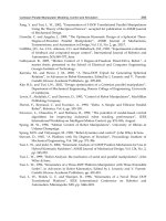
repeatability of 1 µm. A typical exponent of this class of robots is the Sysmelec Autoplace
411 (Fig. 2) (Hesselbach et al., 2005). Another solution for micro assembly robots are
conventional Scara robots in combination with redundant high-precision axes in order to
reach a high resolution. This approach is always combined with additional sensors to
achieve a good repeatability (Höhn, 2001).
Fig. 2. Serial robot Sysmelec Autoplace 411 with Cartesian structure
The development of size-adapted robots is another solution of robots for micro assembly.
Saving costs is only possible by reducing the footprint of an assembly system due to the
demand of a clean room environment for the production of MST products. In recent years,
the reduction of size and costs of micro production systems has been widely discussed in
various papers. Most of these concepts relate to one of the two general groups explained in
the following.
The first group consists of piezo driven, small walking micro robots and handling machines.
These autonomous robots are suitable for positioning small objects such as the MINIMAN
of (Fatikow, 2000), a handling device for samples in a scanning electron microscope. On the
one hand, these micro robots are very promising for new trends such as nano assembly. By
using autonomous robots, difficulties occur regarding the coordination and interaction of
these robots, movement on rough surfaces and energy supply.
The second group describes cost-efficient, size-adapted handling devices, which fill the gap
between piezo driven, small walking micro robots and conventional robots. A possible
solution for this strategy is to determine the highest degree of miniaturization of
conventional robot technology, using innovative, miniaturized machine parts. With these