Electrical Engineering Mechanical Systems Design Handbook Dorf CRC Press 2002819s_8 pot
Bạn đang xem bản rút gọn của tài liệu. Xem và tải ngay bản đầy đủ của tài liệu tại đây (2.17 MB, 41 trang )
Hosek, M., Elmali, H., and Olgac N., 1997b, Centrifugal delayed resonator: Theory and experiments,
Proceedings of ASME Design Engineering Technical Conferences, 16th Biennial Conference on
Mechanical Vibration and Noise, Paper No. DETC97/VIB-3829, September 14–17, 1997, Sacra-
mento, California.
Hosek, M., Elmali, H., and Olgac N., 1999, Centrifugal delayed resonator pendulum absorber, United
States Patent No. 5934424.
Hosek, M. and Olgac, N., 1999, A single-step automatic tuning algorithm for the delayed resonator
vibration absorber, Proceedings of 1999 ASME International Mechanical Engineering Congress
and Exposition, Dynamic Systems and Control Division, 67, 157–164, November 14–19, Nash-
ville, Tennessee.
Hosek, M., Olgac, N., and Elmali, H., 1999, The centrifugal delayed resonator as a tunable torsional
vibration absorber for MDOF systems, Journal of Vibration and Control, 5, 2, 299–322.
Huang, C. and Olgac, N., Proceedings, 2000 American Control Conference, Chicago.
Inman, D. J., 1994, Engineering Vibration, Prentice-Hall, Englewood Cliffs, New Jersey.
Jacquot, R. G., 1978, Optimal dynamic vibration absorbers for general beams, Journal of Sound and
Vibration, 60 (4), 535–542.
Jalili, N. and Olgac, N., 1999, Optimum delayed feedback vibration absorber for flexible beams,
Smart
Structures, NATO Science Series, Kluwer Academic, Amsterdam, 65, 237–246.
Jalili, N. and Olgac, N., 2000, A sensitivity study on optimum delayed feedback vibration absorber,
ASME Journal of Dynamic Systems, Measurement and Control, 122, 2,
314–321.
Kolmanovskii, V.B. and Nosov, V.R., 1986, Stability of Functional Differential Equations, Academic
Press, London.
Marshall, J. E., 1979, Control of Time Delay Systems, Peter Peregrinus Ltd., New York.
MATLAB/SIMULINK, version 5.3, Release R11, 1999, The MathWorks Inc., Natick, Massachusetts.
Nishimura, H., Nonami, K., Cui, W., and Shiba, A., 1993, H
∞
control of multi-degree-of-freedom
structures by hybrid dynamic vibration absorber (experimental consideration of robustness and
control performance), Transactions of the Japan Society of Mechanical Engineers. Part C., 59,
714–720.
Olgac, N., 1995, Delayed resonators as active dynamic absorbers, United States Patent 5,431,261.
Olgac, N., 1996, Single mass dual frequency fixed delayed resonator, United States Patent 5,505,282.
Olgac, N., Elmali, H., and Vijayan, S., 1996, Introduction to dual frequency fixed delayed resonator
(DFFDR), Journal of Sound and Vibration, 189, 355–367.
Olgac, N., Elmali, H., Hosek, M., and Renzulli, M., 1995, High-frequency implementation of delayed
resonator concept using piezoelectric actuators, Proceedings of ACTIVE 95 — 1995 International
Symposium on Active Control of Sound and Vibration, 57–66.
Olgac, N., Elmali, H., Hosek, M., and Renzulli, M., 1997, Active vibration control of distributed systems
using delayed resonator with acceleration feedback, Journal of Dynamic Systems, Measurement
and Control, 119, 380–389.
Olgac, N. and Holm-Hansen, B., 1994, A novel active vibration absorption technique: Delayed resonator,
Journal of Sound and Vibration, 176, 93–104.
Olgac, N. and Holm-Hansen, B., 1995a, Tunable active vibration absorber: The delayed resonator, ASME
Journal of Dynamic Systems, Measurement and Control, 117, 513–519.
Olgac, N. and Holm-Hansen, B., 1995b, Design considerations for delayed-resonator vibration absorbers,
Journal of Engineering Mechanics, 121, 80–89.
Olgac, N. and Hosek, M., 1995, Dual-frequency vibration absorption using delayed resonator with
relative position measurement. Proceedings of ASME Dynamic Systems and Control Division,
ASME International Mechanical Engineering Congress and Exposition, 2, 791, November 12–17,
San Francisco, California.
Olgac, N. and Hosek, M., 1997, Active vibration absorption using delayed resonator with relative position
measurement, Journal of Vibration and Acoustics, 119, 131–136.
Olgac, N. and Jalili, N., 1998, Modal analysis of flexible beams with delayed resonator vibration absorber:
Theory and experiments, Journal of Sound and Vibration, 218(2), 307–331.
8596Ch14Frame Page 279 Friday, November 9, 2001 6:29 PM
© 2002 by CRC Press LLC
Orfanidis S. J., 1996, Introduction to Signal Processing, Prentice Hall, Englewood Cliffs, New Jersey.
Ormondroyd, J. and Den Hartog, J. P., 1928, The theory of the dynamic vibration absorber, Transactions
of ASME, 50, 9–22.
Ozguven, H. N. and Candir, B., 1986, Suppressing the first and second resonance of beams by dynamic
vibration absorbers, Journal of Sound and Vibration, 111(3), 377–390.
Puksand, H., 1975, Optimum conditions for dynamic vibration absorbers for variable speed systems
with rotating and reciprocating unbalance, International Journal of Mechanical Engineering
Education, 3, 145–152.
Rao, S. S., 1995, Mechanical Vibrations, 3
rd
ed., Addison-Wesley, New York.
Renzulli, M., 1996, An algorithm for automatic tuning of the delayed resonator vibration absorber, M.S.
Thesis, University of Connecticut, Storrs.
Renzulli M. E., Ghosh-Roy R., and Olgac N., 1999, Robust control of the delayed resonator vibration
absorber, IEEE Transactions on Control Systems Technology, 7(6), 683.
Rodellar J., Chung L. L., Soong T. T., and Reinhorn A. M., 1989, Experimental digital control of
structures, Journal of Engineering Mechanics, 115, 1245.
Seto, K. and Fumishi, Y., 1991, A Study on Active Dynamic Absorber, ASME paper DE - Vol. 38.
Stepan, G., 1989, Retarded Dynamical Systems Stability and Characteristic Functions, Longman, Lon-
don.
Sun, J. Q., Jolly, M. R., and Norris, M. A., 1995, Passive, adaptive, and active tuned vibration absorbers —
a survey, ASME Transactions, Special 50
th
Anniversary, Design Issue, 117, 234–242.
Thomson, W. T., 1988, Theory of Vibration with Applications, Prentice Hall, Englewood Cliffs, New
Jersey.
Thowsen A., 1981a, An analytic stability test for a class of time-delay systems, IEEE Transactions on
Automatic Control, AC-26, 735.
Thowsen A., 1981b, The Routh-Hurwitz method for stability determination of linear differential-differ-
ence systems, International Journal of Control, 33, 991.
Thowsen A., 1982, Delay-independent asymptotic stability of linear systems, IEE Proceedings, 129, Part
D, 73, 1982.
Valá
ˇ
sek, M. and
Olgac, N., 1999,
New concept of active multiple frequency vibration suppression
technique, Smart Structures, NATO Science Series, Kluwer Academic, 65, 373–382.
Warburton, G. B. and Ayorinde, E. O., 1980, Optimum absorber parameters for simple systems, Earth-
quake Engineering and Structural Dynamics, 8, 197–217.
Wilson, W. K., 1968, Practical Solution of Torsional Vibration Problems, Chapman and Hall, London.
Yang, B., 1991, Noncollocated control of damped string using time delay, Proceedings, 1991
American Control Conference, Boston.
Youcef-Toumi K. and Bobbett J., 1991, Stability of uncertain linear systems with time delay, Journal
of Dynamic Systems, Measurements, and Control, 113, 558.
Youcef-Toumi K. and
Ito O., 1990, A time delay controller for systems with unknown dynamics, Journal
of Dynamic Systems, Measurements, and Control, 112, 133.
Zitek P., 1984, Stability criterion for anisochronic dynamic systems, Acta Technica CSAV, 4, 399.
8596Ch14Frame Page 280 Friday, November 9, 2001 6:29 PM
© 2002 by CRC Press LLC
15
Vibration Suppression
Utilizing Piezoelectric
Networks
15.1 Introduction
15.2 Passive and Semi-Active Piezoelectric Networks
for Vibration Absorption and Damping
15.3 Active-Passive Hybrid Piezoelectric Network
Treatments for General Modal Damping
and Control
15.4 Active-Passive Hybrid Piezoelectric
Network Treatments for Narrowband
Vibration Suppression
15.5 Nonlinear Issues Related to Active-Passive
Hybrid Piezoelectric Networks
15.6 Summary and Conclusions
15.1 Introduction
Because of their electromechanical coupling characteristics, piezoelectric materials have been
explored extensively for structural vibration control applications. Some of the advantages of piezo-
electric actuators include high bandwidth, high precision, compactness, and easy integration with
existing host structures to form the so-called
smart
structures. In a purely active arrangement, an
electric field is applied to the piezoelectric materials (which can be surface bonded or embedded
in the host structure) based on sensor feedback and control commands. In response to the applied
field, stress/strain will be induced in the piezoelectric material and active control force or moments
can thus be created on the host structure to suppress vibration.
In recent years, a considerable amount of work has been performed to further utilize piezoelectric
materials for structural control by integrating them with external electrical circuits to form piezo-
electric networks. Such networks can be utilized for passive, semi-active, and active-passive hybrid
vibration suppressions (Lesieutre, 1998; Tang, Liu, and Wang, 2000). Many interesting phenomena
have been explored and promising results have been illustrated. The objective of this chapter is to
review these efforts and assess the state-of-the-art of vibration control treatments utilizing piezo-
electric networks. The basic concepts and development of passive and semi-active networks are
discussed in Section 15.2. With the introduction of active actions, various issues, and recent
advances regarding active-passive hybrid networks are presented in Sections 15.3 through 15.5.
Kon-Well Wang
Pennsylvania State University
8596Ch15Frame Page 281 Tuesday, November 6, 2001 10:06 PM
© 2002 by CRC Press LLC
15.2 Passive and Semi-Active Piezoelectric Networks
for Vibration Absorption and Damping
In a purely passive situation, piezoelectric materials are usually integrated with an external shunt
circuit (Hagood and von Flotow, 1991; Lesieutre, 1998). As the host structure vibrates, the piezo-
electric layer will be deformed. Because of the electromechanical coupling characteristic, electrical
field/current will then be generated in the shunt circuit. With proper design of the shunt components
(inductor, resistor, or capacitor), one can achieve the so-called electrical damper or electrical
absorber effects.
Soon after Hagood and von Flotow provided the first quantitative analysis of piezoelectric shunt
networks, Hagood and Crawley (1991) applied the resonant shunt piezoelectric (RSP) network to
space truss structures. An important feature of that work is the usage of a synthetic inductor, which
is essentially a circuit with an operational amplifier feeding back current rate, thus simulating the
effect of an inductor. For small piezoelectric capacitance and low structural modes, the optimum
RSP requires a large inductance with low electrical resistance, which could be difficult to realize.
The introduction of the synthetic inductor can effectively circumvent this problem and, more
importantly, ease the tuning of the circuit because the inductance can be changed by varying the
gain of the feedback current rate. Following along the same line, Edberg et al. (1992) developed a
simulated inductor composed of operational amplifiers and passive circuitry connected as a gyrator,
which can produce hundreds or thousands of henries with just a few simple electronic components.
Because the value of simulated inductance may be easily changed by a variable resistor, it may be
possible to have passive damping circuits monitor the frequencies to which they are subjected and
alter their own characteristics in order to optimize the behavior.
From the power-flow point of view, the effect of inductance in the RSP is to cancel the inherent
capacitive reactance of the piezoelectric material. As proposed by Bondoux (1996) the same effect
can be expected by introducing a negative capacitance. Although this negative capacitance is
impossible to achieve passively, it can be realized by using a small operational amplifier circuit
similar to the synthetic inductor. Bondoux compared the negative capacitance shunting and the
RSP and found that the use of a negative capacitance provides a broadband efficiency allowing
multiple-mode damping. A similar conclusion was also drawn by Spangler and Hall (1994) and
Bruneau et al. (1999). In general, the negative capacitance can increase the electromechanical
coupling coefficient and enhance the efficiency of piezoelectric damping in both the resistive shunt
and RSP network. The disadvantages are that the negative capacitance can generate electrical
instabilities (Bondoux, 1996), and the high ratio of capacitance compensation is difficult to achieve
in practice without adding a sensor to the circuit to account for the thermal changes of the
piezoelectric capacitance (Bruneau et al. 1999).
A common thread of the aforementioned studies is the usage of an electronic circuit with operational
amplifiers. Although they are not true semi-active approaches, these studies laid down a foundation
for semi-active (adaptive/variable) absorption and damping research that continues today. An immediate
application of the tunable nature of the synthetic inductor is a self-tuning piezoelectric vibration absorber
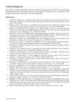
developed by Hollkamp and Starchville (1994) (see Figure 15.1, case a). An RSP network is formed
as an electromechanical vibration absorber and the shunt inductance are controlled through varying
the resistance of a motorized potentiometer in the synthetic inductor, which enables on-line adjustment
of the RSP tuning to maximize the performance function. In their approach, an ad hoc performance
function was selected as the ratio of the RMS voltage across the shunt and the RMS structure response.
If the ratio increases, the change in the inductance is in the proper direction and the inductance is again
changed in that direction. If the ratio decreases, the direction is reversed. Although one deficiency of
this simple control scheme is that the absorber will never settle on a single tuning value, it is effective
for slow time-varying systems which can tolerate the tuning fluctuations and the time it takes to initially
tune the absorber.
8596Ch15Frame Page 282 Tuesday, November 6, 2001 10:06 PM
© 2002 by CRC Press LLC
Wang et al. (1996) proposed a semi-active RSP scheme with variable inductance and resistance
(see Figure 15.1, Case b). Their focus was on an improved control law that can handle not only
quasi-steady-state scenarios but also structures with more general disturbances such as nonperiodic
and transient loadings. They found that in such a semi-active configuration, the rates of the total
system energy (the main structure mechanical energy plus the electrical and mechanical energies
of the RSP) and the main structure energy are dependent on the circuit resistance, inductance, and
inductance rate. It was recognized that an effective approach would be to reduce the total system
energy while constraining the energy flowing into the main structure. Because two objectives were
to be accomplished and they could contradict each other, an algorithm using variable resistance
and changing rate of inductance as control inputs was developed to balance the energies. By
selecting the total system energy as a Lyapunov functional, one can guarantee system stability
through ensuring a negative rate of the system energy, while at the same time maximizing energy
dissipation of the vibrating host structure.
Davis et al. (1997) and Davis and Lesieutre (1998) studied the possibility of tuning a mechanical
absorber using shunted piezoelectric materials. The idea was initiated from the inertial piezoelectric
actuator concept developed for structural vibration control (Dosch et al., 1995) where the forcing
element in a proof mass actuator was replaced by a piezoelectric element with dual-unimorph
displacement amplification effect. An important finding is that in such a configuration, the absorber
stiffness is dependent on the ratio of the electrical impedance of the open circuit piezoelectric
capacitance to the electrical impedance of the external shunt circuit. Therefore, by varying the
impedance of an external shunt circuit, the natural frequency and, in some cases, the modal model
damping of the vibration absorber will vary (Davis et al. (1997). Based upon this, Davis and
Lesieutre (1998) developed an actively tuned solid-state piezoelectric vibration absorber. Because
their goal was to maintain minimum structural response at a certain (may be varying) frequency,
they adopted a capacitive shunting scheme without a resistive element, as damping is not needed
in such applications. It should be noted that depending on different performance requirements,
different shunting schemes could be optimally designed. To obtain variable capacitance, a “ladder”
circuit of discrete capacitors wired in parallel was used. At a given time, the controller switches
on some or all of the capacitors in parallel with the piezoelectric element, thereby changing the
absorber stiffness and tuning the absorber frequency to the favorable value. The range of the
adjustable stiffness is nevertheless limited by the piezoelectric electromechanical coupling coeffi-
cient. On a benchmark experimental setup, Davis and Lesieutre (1998) achieved a
±
3.7% tunable
frequency band relative to the center frequency. Within the tuning band, increases in performance
(vibration amplitude reduction) beyond passive performance were as great as 20dB. In addition,
the averaged increase in performance across the tunable frequency band was over 10dB.
Piezoelectric materials realize a significant change in mechanical stiffness between their open-
circuit and short-circuit states. This property was exploited by Larson et al. (1998) to develop a
high-stroke acoustic source over a wide frequency range. By switching between the open-circuit
FIGURE 15.1
Schematics of some semi-active RSP damper/absorbers. Case (a): R = inherent resistance in the
circuit; L on-line adjusted. Case (b): R and L on-line adjusted.
Inductance
Resistan
ce
Structure
Piezoelectric
Transdu
cer
8596Ch15Frame Page 283 Tuesday, November 6, 2001 10:06 PM
© 2002 by CRC Press LLC
and short-circuit states, the acoustic driver’s stiffness (and, therefore, its natural frequency) can be
changed, allowing it to track a changing frequency with high amplitude. While Larson et al. (1998)
proposed a practical realization of such a state-switched source for applications in active sonar
systems, underwater research, and communication systems, Clark (1999a) found it is also useful
in forming a semi-active piezoelectric damper. Using a typical energy-based control logic (Leit-
mann, 1994), Clark (1999a) illustrated how a piezoelectric actuator can be switched between the
high and low stiffness states to achieve vibration suppression (see Figure 15.2, Case a). When the
system is moving away from equilibrium, the circuit is switched to the high-stiffness state (open
circuit), and the circuit is switched to the low-stiffness state (short circuit) when the system is
moving toward equilibrium. This has the effect of suppressing deflection away from equilibrium,
and then at the end of the deflection quarter-cycle, dissipating some of the stored energy so that it
is not returned to the structure. In the open-circuit case, deflection stores energy by way of
mechanical stiffness and the piezoelectric capacitance effect. When the system is switched to the
short-circuit state, the charge stored across the capacitor is shunted to ground, effectively dissipating
that portion of the energy. Clark (1999b) further studied the case that used a resistive shunt instead
of a pure short circuit at low-stiffness state (see Figure 15.2, Case b), and compared the state-
switching control with an optimally tuned passive resistive shunt. It was shown that for the example
used in the study the optimal resistive shunt performed better for suppressing transient vibrations.
The state-switching approach, however, provided better performance for off-resonance (particularly
low-frequency) excitations, and was very robust to changes in system parameters.
Richard et al. (1999) also developed a piezoelectric damper using the switching concept (see
Figure 15.2, Case a). The switch itself consisted simply of a pair of MOSFET transistors and little
power was needed. The main difference between their approach and that proposed by Clark (1999a,
1999b) is in the switching law. Instead of switching between open and short circuits at different
quarter-cycles of vibration, Richard et al. (1999) proposed to maintain the open circuit as the
nominal state, and briefly switch to the short-circuit state to dump the electrical energy only when
the structure displacement reaches a threshold value. Although no analytical results were available,
they found that the best vibration suppression was achieved for a threshold corresponding to a
maximum and a minimum of the displacement or output voltage in one vibration period. The time
interval corresponding to the short-circuit time is also important and can be tuned. It was experi-
mentally shown that the shortest time led to the best damping efficiency. They demonstrated
enhanced damping performance of the proposed device over the passive resistive shunt.
Warkentin and Hagood (1997) studied a nonlinear piezoelectric shunting scheme with a four-
diode full-wave rectifier and a DC voltage source. If the vibration amplitude is small, the voltage
produced by the accumulation of charge on the piezoelectric capacitance is less than the DC voltage.
Under this condition, all the diodes are reverse biased and no current will flow through the shunt,
and the system is at the open-circuit condition. For larger motions, the diodes are turned on, current
flows through the shunt, and the piezoelectric voltage is clipped at positive and negative DC voltage
FIGURE 15.2
Schematics of some semi-active piezoelectric switching dampers. Case (a) Switching between open
and short circuit states, R = 0. Case (b) switching between open circuit and resistive shunting, R = optimal passive
value.
Resistance
Structure
Piezoelectric
Transdu
cer
Switch
8596Ch15Frame Page 284 Tuesday, November 6, 2001 10:06 PM
© 2002 by CRC Press LLC
by the rectifier and the voltage source. The arrangement of the diodes ensures that the current
always flows into the positive terminal of the DC source. If the DC source is implemented as a
rechargeable battery or a regulated switching power circuit, the vibration energy removed from the
structure may thus be recovered in a usable electrical form. The different stiffness exhibited at the
open-circuit and short-circuit phases, combined with the voltage offset from the shunt voltage
source, will produce a mechanical hysteresis. Although its performance was not as good when
compared with the loss factor achieved by a conventional resistive shunt operating at optimum
frequency, the rectified DC shunt is a frequency-independent device and its potential energy
recovery ability remains an attractive feature. Warkentin and Hagood (1997) also studied resistive
shunting with variable circuit resistance. An optimization approach was used to determine the ideal
periodic resistance time history. The effective loss factors obtained in the simulations assuming
sinusoidal deformation exceeded twice the values achieved by the fixed resistive shunt.
15.3 Active-Passive Hybrid Piezoelectric Network Treatments
for General Modal Damping and Control
While the earlier investigations in RSP networks mostly focused on passive applications, it is clear
that shunting the piezoelectric does not preclude the use of a coupled piezoelectric materials–shunt
circuit as active actuators. That is, by integrating an active current or voltage control source with
the passive shunt, one can achieve an active-passive hybrid piezoelectric network (APPN) config-
uration (Figure 15.3). The passive damping can be useful in stabilizing controlled structures in the
manner analogous to proof mass actuators (Miller and Crawley, 1988; Zimmerman and Inman,
1990; Garcia et al., 1995). Hagood et al. (1990) developed a general modeling strategy for systems
with dynamic coupling through the piezoelectric effect between a structure and an electrical
network. Special attention was paid to the case where the piezoelectric electrodes are connected
to an arbitrary electrical circuit with embedded voltage and current sources. They obtained good
agreement between the analytical and experimental results, and concluded that the inclusion of
electrical circuitry between the source and the structure gives the designer greater ability to model
actual effects and to modify the system dynamics for closed-loop controls.
Niezrecki and Cudney (1994) addressed the power consumption characteristics of the piezoelec-
tric actuators. The electrical property of a piezoelectric actuator is similar to a capacitor, which
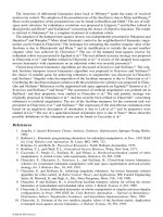
FIGURE 15.3
Schematics of active-passive hybrid piezoelectric networks. V
p
: equivalent voltage generator attrib-
uted to the piezoelectric effect; V
s
: voltage source; I
s
: current or charge source; C: piezo capacitance; R: resistance;
L: inductance. (From Tang, J., Liu, Y., and Wang, K. W.,
Shock and Vibration Digest
, 32(3), 189–200, ©2000, Sage
Publication, Inc.)
(a) (b)
(c)
(d)
R
R
R
L
L
L
L
V
s
V
s
I
s
I
s
V
p
V
p
V
p
V
p
C
C
C
C
piezo piezo
piezo piezo
R
8596Ch15Frame Page 285 Tuesday, November 6, 2001 10:06 PM
© 2002 by CRC Press LLC
leads to a reactive current that provides only an electromagnetic field and does not perform work
or result in useful power being delivered to the load. Therefore, the power factor of a piezoelectric
actuator is approximately zero. Niezrecki and Cudney (1994) proposed to add an appropriate
inductance to correct the power factor to unity within a small but useful frequency range. They
studied two cases: adding inductors in parallel and in series with the piezoelectric actuator. In both
cases, a resonant LC circuit was formed, and around the resonant frequency the reactive elements
cancelled and the phase between current and voltage became zero, resulting in a unity power factor.
They incorporated the internal resistance of the piezoelectric actuators and inductors in their
analysis. Implementing the parallel LC circuit reduced the current consumption of the piezoelectric
actuator by 75% when compared to the current consumption of the actuator used without an
inductor. Implementing the series LC circuit produced a 300% increase in the voltage applied to
the actuator compared to the case when no inductor was used. In both cases, the apparent power
was reduced by 12dB.
From the above work, one may realize that the RSP network not only will increase the system’s
passive damping, but also will greatly increase the active control authority around the shunt resonant
frequency. Agnes (1994, 1995) examined the simultaneous passive and active control actions of an
RSP network through open-loop analyses. A modal model was developed to evaluate the hybrid
vibration suppression effect, and open-loop experiments were performed for validation. Using
Hagood and von Flotow’s optimal RSP tuning results (1991) to determine the shunt circuit param-
eters, it was observed that not only the passive damping effect was significant, the modal response
of the structure to the input voltage or current signal is also increased greatly. Using voltage as the
driving source (Figure 15.3a), the shunted system frequency response was similar to the nonshunted
response below the tuned (shunted mode) frequency, but exhibited greater roll-off above the tuned
frequency. For broadband control, this would help prevent spillover because the magnitude of the
response is, in general, lower for higher modes. When current source was used (Figure 15.3c), the
shunted system’s active action was less effective below the tuned frequency when compared to the
nonshunted case, but no roll-off was observed in the high-frequency region. Tsai (1998) and Tsai
and Wang (1999) also performed experimental investigations to illustrate the shunt circuit’s passive
damping ability (Figure 15.4a), as well as its active authority enhancement ability (Figure 15.4b)
in APPN. Through exciting the structure with the actuator, they compared the open-loop structural
response of the integrated APPN and the configuration with separated RSP and a piezoelectric
actuator. While the two configurations have the same passive damping ability, the APPN configu-
ration can drive the host structure much more effectively than the separated treatment does
(Figure 15.4b), which clearly demonstrated the merit (high active authority) of the integrated APPN
design.
FIGURE 15.4
Experimental results on system passive damping and active authority of APPN. (From Tang, J.,
Liu, Y., and Wang, K. W.,
Shock and Vibration Digest
, 32(3), 189–200, ©2000, Sage Publication, Inc.)
160 165 170 175 180 185 190 195 200 205
-60
-55
-50
-45
-40
-35
-30
-25
-20
Frequency (Hz)
No Shunt
With Shunt
Passive damping
Frequency (Hz
)
160 165 170 175 180 185 190 195 200 205
-50
-45
-40
-35
-30
-25
-20
-15
-10
Integrated APPN
Separate
d
Active authority
Structure response (db) under disturbance
Structure response (db) under actuator input
(a) (b)
8596Ch15Frame Page 286 Tuesday, November 6, 2001 10:06 PM
© 2002 by CRC Press LLC
While Hagood and von Flotow’s tuning results (1991) can minimize the maximum frequency
response for a passive system, they are not necessarily good choices for an active-passive hybrid
system. That is, the question of how to determine the system’s active and passive parameters to
achieve efficient hybrid vibration control still remains. From the driving voltage (control input)
standpoint, the circuit inductance value will determine the electrical resonant frequency around
which the active control authority will be amplified, and although appropriate resistance is required
to achieve broadband passive damping, resistance in general reduces the active authority amplifi-
cation effect (Tsai and Wang, 1999). To balance between active and passive requirement conflicts
and performance tradeoffs and achieve an optimal configuration, a scheme was synthesized to
concurrently design the passive elements and the active control law (Kahn and Wang, 1994, 1995;
Tsai and Wang, 1996, 1999). This approach is to ensure that active and passive actions are configured
in a systematic and integrated manner. The strategy developed is to combine the optimal control
theory with an optimization process and to determine the active control gains together with the
values of the passive system’s parameters (the shunt circuit resistance and inductance). The proce-
dure contains two major steps: (1) for a given set of passive parameters (resistance
R
and inductance
L
), form the system equations into a regulator control problem and derive the active gains to
minimize a cost function representing vibration amplitude and control effort via the optimal control
theory (Kwakernaak and Sivan, 1972); (2) for each set of the passive control parameters
R
and
L
,
an optimal control exists with the corresponding minimized cost function,
J
, and control gains.
That is,
J
is a function of
R
and
L
. Therefore, utilizing a nonlinear programming algorithm (Arora,
1989), one can determine the resistance and inductance that further reduce
J
. Note that as the
R
and
L
values are varied during the optimization process, step (1) is repeated to update the active
gains simultaneously. In other words, by concurrently modifying the values of the active gains and
passive parameters, an “optimized” optimal control system can be obtained.
The APPN system and the control/design scheme have been evaluated on various types of
structures. In a multiple APPN ring vibration control problem (Tsai and Wang, 1996), a random
sequence was generated to compare the structure displacements and control efforts (voltages) of
the uncontrolled, the active, and the active-passive systems. From the results, it is clear that the
active-passive action resulted in significant vibration reduction compared to the uncontrolled case
(a 25dB reduction in standard deviation). In addition, the hybrid approach also outperformed the
purely active system (Figure 15.5). Figure 15.5 also shows that the active-passive hybrid controller
requires much less voltage than the active controller does.
Based on this simultaneous optimal-control/optimization strategy, Tsai (1998) and Tsai and Wang
(1999) performed a detailed parametric analysis for the APPN design, showing that the optimal
FIGURE 15.5
Comparisons of purely active and active-passive hybrid systems: performance and required voltage
for vibration control. (From Tsai, M. S. and Wang, K. W.,
Smart Materials and Structures
, 5(5), 695–703, ©1996,
IOP Publishing, Inc.)
Purely Active
Vibration Amplitude (mm)
Active-Passive Hybrid
0 1 2
-4
0
4
0 1 2
-4
0
4
Time (sec)
Purely Active
Control Voltage (Volts)
Active-Passive Hybrid
0 1 2
-500
0
500
0 1 2
-500
0
500
Time (sec)
8596Ch15Frame Page 287 Tuesday, November 6, 2001 10:06 PM
© 2002 by CRC Press LLC
resistance and inductance values for the hybrid system could be quite different from those of the
passive system, especially when demand on performance is high and/or when the number of
actuators is much smaller than the number of controlled modes. For the APPN configuration, when
the weighting on control effort increases, the optimal resistance (
R
) and inductance (
L
) values using
the concurrent design will approach those derived from the passive optimization procedure. In
general, when demand on control performance increases, the resistance value becomes smaller to
enhance the active authority amplification effect, and inductance reduces to cover a wider frequency
bandwidth. The excitation bandwidth also plays an important role, as it determines to which mode
the
RL
values will be tuned.
Tsai and Wang (1998) addressed the robustness issue in systems controlled by APPN. They
developed an algorithm with coupled
µ
synthesis (Zhou et al., 1996) and an optimization process
to design a robust hybrid controller. In their example, they found that the structural uncertainty
level that the hybrid controller can tolerate (the maximum uncertainty level at which the
µ
synthesis
approach can find a solution) is much higher than what a purely active controller can tolerate, and
thus the hybrid controller is much more robust than a purely active system.
Tang and Wang (1999a) applied the active-passive hybrid piezoelectric networks to rotationally
periodic structures. Consisting of identical substructures, a rotationally periodic structure is essen-
tially a multi-degrees-of-freedom system. The coupling between the substructures will split the
otherwise repeated substructure frequency to a group of frequencies, which creates the problem of
how to tune the shunt. By utilizing the unique property of rotationally periodic structures, Tang
and Wang (1999a) developed an analytical method to determine the passive and active parameters
for the control design, where the active control was used to compensate for the mistuning effect
due to substructure coupling. The overall effect of the active and passive actions minimizes the
maximum frequency response for all modes. Identical shunting circuit and control gains were
applied to each substructure, which could bring convenience in implementations.
As mentioned earlier, while the resistor in the hybrid control system provides passive damping,
it also tends to reduce the active control authority by dissipating a portion of the control power
(Tsai and Wang, 1999). To further improve the efficiency of the active-passive hybrid piezoelectric
network, Morgan and Wang (1998) proposed using a variable resistor in the circuit. The key feature
in this control design was the introduction of a parametric control law to adjust the variable resistor.
When electrical energy is flowing into the actuator/structure from the voltage source, the circuit is
shorted to reduce the loss of control power. When the energy is flowing out of the actuator/structure,
a positive value of resistance is selected for passive energy dissipation. They suggested using a
digital potentiometer connected to the parametric controller to achieve the hardware realization.
Their analysis showed that the parametric control law can significantly increase the efficiency of
the active-passive hybrid control system, especially for narrowband and/or low to moderate gain
applications. The reduced control effort could make it an attractive option for applications when
minimizing the power consumption is critical.
Tsai and Wang (1999) concluded that the APPN will become less effective when the excitation
bandwidth increases, because its passive damping and active authority amplification effects are
narrowbanded. To circumvent this, they proposed to integrate the APPN with broadband damping
treatments (Tsai and Wang, 1997). Specifically, they studied the integration with the enhanced
active constrained layer (EACL) configuration (Liao and Wang, 1996, 1998a, 1998b; Liu and Wang,
1999), to which edge elements are added to the active constraining layer (ACL) (Park and Baz,
1999) to increase the transmissibility and active action authority. They found that adding the hybrid
network to a traditional active constrained layer (ACL) treatment will not lead to much extra
damping because of low transmissibility between the host structure strain and the piezoelectric
coversheet deformation. However, the integration of APPN with EACL can achieve high damping.
A comparison of the APPN, EACL, and combined APPN-EACL damping treatments was per-
formed. An objective function was defined to reflect the vibration amplitude and control effort. In
general, smaller objective function means better overall performance and thus better hybrid damping
8596Ch15Frame Page 288 Tuesday, November 6, 2001 10:06 PM
© 2002 by CRC Press LLC
ability. The minimized objective function,
J
, for different configurations vs. excitation bandwidth
was obtained (Figure 15.6). As shown in the figure, APPN outperforms EACL when the bandwidth
is small, but becomes less effective than EACL as bandwidth increases. On the other hand, the
combined APPN-EACL system can outperform the individual APPN and EACL cases, under both
narrowband and broadband excitations.
So far, in most active-passive hybrid piezoelectric network studies, only one of the series
configurations has been considered. That is, the resistor, the inductor, and the power source (voltage
source) were all connected in series with the piezoelectric actuator (Figure 15.3a). Wu (1996) found
that by connecting the resistor and inductor in parallel with the piezoelectric material, one can
achieve a similar passive vibration absorbing/damping effect as that of the series configuration
proposed by Hagood and von Flotow (1991). Combining parallel and series passive configurations
with the parallel and series active driving, one can envision a few different active-passive hybrid
piezoelectric network configurations, some of which are shown in Figures 15.3b–d. From the
viewpoint of linear system superposition, the structure response is a summation of that caused by
external disturbance and that caused by control input. Therefore, for the passive effect to function
normally in the absence of the active control input, we should use charge or current control when
the power source is in parallel with the shunting elements, such as those shown in Figures 15.3b
and c. Although one has to resort to complicated circuit design to obtain a charge source, it has
the potential benefit of avoiding the piezoelectric hysteresis (Main et al., 1995). However, it should
be noted that different configurations yield roughly the same passive and hybrid damping abilities
(Tang and Wang, 2001).
15.4 Active-Passive Hybrid Piezoelectric Network Treatments
for Narrowband Vibration Suppression
The focus of Section 15.3 is systems utilizing APPN for general modal damping and control. It
has also been found that the APPN configuration could be very effective for narrowband vibration
rejection. The active-passive hybrid approach is especially attractive for narrowband disturbances
with varying frequencies (an example of this type of excitation is a machine with a rotating
unbalance — the frequency variation could be a slow drift due to changes in operating conditions
or a rapid spin-up when the machine is turned on), as discussed in this section.
While a passive piezoelectric vibration absorber (piezoelectric materials with passive resonant
shunt) is effective for harmonic disturbance rejection (Hagood and von Flotow, 1991), it could be
sensitive to frequency variations and system uncertainties. As stated in Section 15.2, semi-active piezo-
electric absorber concepts have been proposed to suppress harmonic excitations with time-varying
FIGURE 15.6
Objective function (
J
) comparison between different configurations.
10
2
10
3
1
2
3
4
5
6
7
APPN Alone
EACL Alone
APPN-EACL
J
3x10
3
Frequency (HZ)
8596Ch15Frame Page 289 Tuesday, November 6, 2001 10:06 PM
© 2002 by CRC Press LLC
frequencies. The implementation of these semi-active absorbers requires either a variable inductor
or a variable capacitor element. While they are conceptually valid, both of these methods have
some inherent limitations. For instance, the variable capacitor method (Davis et al., 1997) limits
tuning of the piezoelectric absorber to a relatively small frequency range. The variable inductor
approach (Hollkamp and Starchville, 1994), which is usually accomplished using a synthetic
inductance circuit, can add a significant parasitic resistance to the circuit that is generally undesirable
for narrowband applications. In either case, the variable passive elements can be difficult to tune
rapidly with high accuracy.
With the above arguments, Morgan et al. (2000) and Morgan and Wang (2000) developed a high-
performance active-passive hybrid alternative to the semi-active absorbers, utilizing the APPN
configuration. Throughout this study, the system being considered was a generic mechanical system
with a single piezoelectric actuator attached. The piezoelectric was shunted with an
RL
circuit as
well as an active voltage source (Figure 15.3a). The passive inductance value was tuned to a nominal
excitation frequency. Because the interest here is to use the APPN absorber characteristic to suppress
vibrations at distinct frequencies, low damping (resistance) is required in the absorber. Therefore,
other than the inherent resistance in the circuit, no extra passive resistor was added.
The active control law consists of three modules. The first part of the control law is designed to
imitate a variable inductor so that the absorber is always tuned to the correct frequency. In addition,
an active negative resistance action is used to reduce the absorber damping (inherent resistance in
the circuit) and increase the absorber narrowband performance. To further enhance the robustness
of the piezoelectric absorber, the system’s apparent electromechanical coupling is increased using
the third active action. The advantages of the active inductor include fast and accurate adjustment,
no parasitic resistance, and easier implementation compared to a semi-active inductor. To ensure
that the active inductance is properly tuned, an expression for optimal tuning on a general multiple-
degrees-of-freedom (MDOF) structure was derived. The closed-loop inductance was achieved using
this optimal tuning law in conjunction with an algorithm that estimates the fundamental frequency
of the measured excitation. Details of the mathematical formulation and derivation can be found
in Morgan et al., 2000 and Morgan and Wang, 2000.
The APPN adaptive absorber concept was implemented and experimentally verified on a lab
fixture. Details of the test procedure and setup are described in Morgan and Wang (2000). Two test
cases were considered: the first case is for an off-resonant excitation, and the second is for an
excitation near a resonant frequency of the structure. The baseline system for the resonant excitation
case is an optimally damped passive piezoelectric absorber. That is, the absorber is tuned to the
resonant frequency and sufficient damping (resistance) is added to give a flat frequency response
around the resonant frequency. In the off-resonant case, a passive absorber would be a poor choice
for an excitation of varying frequency because of its small effective bandwidth. Therefore, the
baseline for the off-resonant case is selected to be the response of the structure with the piezoelectric
actuator shorted (no shunt circuit). The inputs to the controller are the structure response signal,
the voltage across the passive inductor, and the excitation signal. The controller also contained a
frequency estimation algorithm, which uses the measured excitation signal to continually estimate
the excitation frequency.
The purpose of this experiment was to study the performance of the system when subjected to
a harmonic excitation with varying frequency. The simplest such excitation is a linear chirp signal,
which is a sinusoid of linearly increasing frequency. The three parameters that characterize the
chirp signal are the nominal frequency
f
o
, the bandwidth of the frequency variation
∆
, and the
frequency rate of change (Hz/s). For the linear chirp used here the frequency starts at (
1–
∆
)
f
o
at
time
t
s
and increases at a rate of until it reaches a maximum frequency of (
1+
∆
)
f
o
at time
t
f
. In
this experiment, the nominal excitation frequency and bandwidth were constant in each case and
the frequency rate of change was varied. Four tests were carried out for both the near-resonant and
off-resonant cases, with the frequency rate of change varying from 2 to 8 Hz per second. The
excitation was applied at time
t
= 0, but the data acquisition system was set to have a trigger delay
˙
f
˙
f
8596Ch15Frame Page 290 Tuesday, November 6, 2001 10:06 PM
© 2002 by CRC Press LLC
of
t
s
= 1 second. The purpose of this delay is to discard the large transient response caused by
initially applying the excitation, which would give a better estimate of the performance of the
system under extended operating conditions.
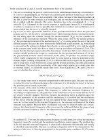
Experimental results for the off-resonant case are shown in Figure 15.7. The excitation bandwidth
used for the off-resonant case is ±10% of the nominal frequency, which corresponds to approxi-
mately 40 Hz. These plots show the response envelopes for the cases = 2 Hz/s and = 8 Hz/s.
From these results it appears that performance of the active-passive absorber is relatively unaffected
by the frequency rate of change. This is somewhat surprising because the optimal tuning is
determined using a quasi-steady-state assumption, which is only valid for excitations with very
slowly changing frequency. The conclusion is that the combination of the quasi-steady-state tuning
law and the active coupling enhancement allows the adaptive absorber to achieve good performance
even for rapidly varying excitations. The combination of a rapidly changing excitation frequency
and a very wide frequency bandwidth is a difficult problem for a semi-active device. However, the
active-passive piezoelectric absorber presented here could have the performance and robustness
necessary for these applications.
Experimental results for two of the near-resonant cases are shown in Figure 15.8. Once again
we see that performance of the active-passive absorber is relatively unaffected by the frequency
rate of change. Although the performance of the optimal passive absorber baseline is already much
better than the original system (no absorber), the adaptive active-passive absorber still can outper-
form the baseline system significantly.
Through extensive parametric studies (Morgan and Wang, 2000), the proposed design was also
compared with two active and active-passive vibration control methods: the Filter-X algorithm (Fuller
et al., 1996) for off-resonant excitation and the concurrent APPN optimal control-optimization process
FIGURE 15.7
Experimental response (sensor voltage readings) envelopes (off-resonant case),
f
o
= 205 Hz. (a) =
2Hz/s, (b) = 8 Hz/s.
5 10 15 20
0.
02
0.
04
0.
06
0.
08
0.
1
short circuit
closed l
oop
2 3 4 5 6
0.
02
0.
04
0.
06
0.
08
0.
1
time (sec.)
short circuit
closed l
oop
(a)
(b)
˙
f
˙
f
˙
f
˙
f
8596Ch15Frame Page 291 Tuesday, November 6, 2001 10:06 PM
© 2002 by CRC Press LLC
(Tsai and Wang, 1999) for near-resonant situation. It was shown that the adaptive active-passive
absorber can outperform the two systems significantly while requiring less control effort. These
parametric studies also illustrated the effects of the absorber parameters and excitation character-
istics on the performance of the adaptive active-passive piezoelectric absorber design.
While promising, the system proposed by Morgan et al. (2000) and Morgan and Wang (2000)
is for suppression of excitations with only a single dominant frequency. To further enhance and
expand the ability of such a device, a multi-frequency adaptive piezoelectric vibration absorber
design was developed (Morgan and Wang, 2001). Building upon the single-frequency disturbance
rejection network configuration, multiple circuit branches and an additional active law were added.
The active control law effectively decouples the dynamics of the individual circuit branches. This
decoupling action allows the tunings of the multi-frequency absorber to be calculated using an
analytical optimal tuning law. The proposed design was shown to be effective for simultaneously
suppressing two harmonic excitations with time-varying frequencies, and it can achieve better
performance while requiring less control power than the Filtered-X algorithm. The design and
analysis presented can be extended in a straightforward manner to cases with more excitation
frequencies.
15.5 Nonlinear Issues Related to Active-Passive Hybrid
Piezoelectric Networks
As mentioned, the piezoelectric network can result in high-performance vibration control through
the dual effects (passive damping and active authority enhancements) of the shunt circuit. On the
FIGURE 15.8
Experimental response (sensor voltage readings) envelopes (near-resonant case),
f
o
= 92 Hz. (a) =
2 Hz/s, (b) = 8 Hz/s.
1.5 22.5 3
0
0.2
0.4
0.6
0.8
1
time (sec.)
passive absorber
closed l
oop
0.1
0.2
0.3
0.4
0.5
0.6
0.7
0.8
0.9 passive absorber
closed l
oop
2
468
10
(a)
(b)
˙
f
˙
f
8596Ch15Frame Page 292 Tuesday, November 6, 2001 10:06 PM
© 2002 by CRC Press LLC
other hand, high performance corresponds to a high electrical field across the piezoelectric material,
especially under high loading conditions. When the electrical field level is high, the linear assump-
tion often made in most piezoelectric actuator-based systems (the linear constitutive relation
between the stress, strain, electrical field, and electrical displacement of the piezoelectric material)
may no longer be valid. This is because the material hysteresis and the high-order nonlinear
relationship between the mechanical response and electrical field could become very significant
when a high electric field occurs on the piezoelectric actuators.
In recent investigations performed by Tang et al. (1999) and Tang and Wang (1999b, 2000), the
nonlinear behavior of the piezoelectric material was investigated experimentally and analytically.
Through lab tests, one can clearly see the complexity of the material property, especially at high
field levels. This fact suggests that one way to utilize the high field (high authority) regime is to
consider the various nonlinear phenomena as uncertainties and develop robust controls to compen-
sate for such uncertainties. By treating the nonlinearity (or part of it) as bounded uncertainties, a
constitutive relation is proposed. For example, if the linear constitutive relation is used as the basic
model, the actual actuation strain at a certain field will be the linear deterministic value plus some
bounded uncertainty (Tang et al., 1999). For one-dimensional structures, the modified constitutive
equations can be expressed in the following form,
where , ,
D,
and represent the stress, strain, electrical displacement (charge/area), and electrical
field (voltage/length along the transverse direction) within the piezoelectric patch, respectively, and
, , and are the Young’s modulus, piezoelectric constant, and dielectric constant of the
material. Here, represents the uncertainty in the strain-field relation, which is bounded as
. The bounds can be selected according to the maximum field level that the actuator will
undergo and identified from experimental data.
Given the new constitutive equation and uncertainty bounds, a robust control algorithm based
on the of sliding mode theory (Slotine and Li, 1991; Utkin, 1993) was then developed to compensate
for the piezoelectric nonlinearities (Tang et al., 1999; Tang and Wang, 1999b, 2000). In general,
the dynamics of a system so controlled consist of a reaching mode and a sliding mode. The strategy
for designing a sliding mode controller involves: (1) the design of a switching manifold (sliding
surface) on which the system will be asymptotically stable (the so-called sliding mode, where fast
convergence is desired); and (2) designing a controller which can force the state trajectory to reach
the switching manifold in finite time (the so-called reaching mode, where a brief reaching time is
desired). When all the nonlinearities were considered as uncertainties, a linear-quadratic regulator
(LQR) optimal control formulation (Kwakernaak and Sivan, 1972) was used to set up the sliding
surface and ensure stability on the surface (Tang et al., 1999; Tang and Wang, 2000). When the
high-order nonlinearity was included in the model and the other nonlinearities were treated as
uncertainties, the Lyapunov stability approach was utilized to select the sliding surface (Tang and
Wang, 1999b).
The effectiveness of the proposed approach was demonstrated through experimental studies and
numerical analyses on vibration control of an APPN-treated cantilever beam structure. For the
purpose of comparison, the simulation results of the beam tip displacement for the linear optimal
controller are shown in Figure 15.9 (upper plot). The dashed line represents the ideal situation
where there are no piezoelectric nonlinearities. However, since the voltage across the piezoelectric
material is high, the actual result is given by a solid line, where the piezoelectric nonlinearities are
simulated as bounded uncertainty. The performance of the linear controller is obviously degraded
by the piezoelectric nonlinearities. The sliding mode control result considering all the piezoelectric
nonlinearities as uncertainties (Tang and Wang, 2000) is then illustrated in Figure 15.9 (lower plot),
τε
εε β
=−
=− − +
EhD
Eh D
p 31
31 0 33
()
τ ε E
E
p
h
31
β
33
ε
0
||
*
εε
0
<
8596Ch15Frame Page 293 Tuesday, November 6, 2001 10:06 PM
© 2002 by CRC Press LLC
which clearly shows much better performance. Here, for a fair comparison, the two controllers are
designed so that they utilize the same RMS value of control power input. These results illustrate
that with such a nonlinear robust controller, one can fully utilize the high authority characteristics
of the APPN system.
15.6 Summary and Conclusions
The major findings and achievements to date in vibration control utilizing piezoelectric networks
can be summarized as follows:
• Passive and semi-active tuning of piezoelectric circuit elements can be effective in various
damping and vibration absorption applications, especially for systems with no variations or
under slow/small changes. Most of the control algorithms are based on energy or power
analysis, and through adjustable resistance, inductance, and capacitance, as well as open- to
short-circuit state switching.
• To further enhance the performance of piezoelectric networks, active voltage or current
sources have been added to form an active-passive hybrid piezoelectric network (APPN).
Circuit elements not only can provide passive damping, they also can increase the treatment’s
active authority. To tune the system properly for general modal damping and control appli-
cations, one approach is to employ a concurrent optimization scheme and simultaneously
synthesize the active gains and passive parameters. Such an APPN approach could outperform
a purely active system with less control effort.
• The active actions in an active-passive hybrid piezoelectric network can also be used to tune
passive component parameters. Such an approach merely adds a dynamic compensator, with
gains emulating the circuit variables and the electromechanical coupling parameter. This
feature could be especially effective for rejecting narrowband excitations with variable
frequencies, where the APPN adaptive absorber effect is utilized.
• The shunt circuit could significantly increase the APPN active authority through increasing
the voltage across the piezoelectric material. That is, high performance corresponds to high
electrical field, especially under high loading conditions. When the electrical field level is
high, piezoelectric nonlinear characteristics should be considered in designing and controlling
the system. One effective approach to utilize the nonlinear high authority features of the
FIGURE 15.9
Beam tip vibration amplitude. Upper plot: linear control (dashed line, ideal case without piezoelec-
tric nonlinearity; solid line, realistic case with piezoelectric nonlinearity). Lower plot: Sliding mode control com-
pensating for piezo nonlinearity.
sliding mode control
time (s)
0 2
-6
0
6
x 10
-5
linear optimal control
0 2
-6
0
6
x 10
-5
8596Ch15Frame Page 294 Tuesday, November 6, 2001 10:06 PM
© 2002 by CRC Press LLC
APPN is to synthesize a nonlinear robust controller (e.g., the sliding mode controller dis-
cussed in this chapter) to include and compensate for the actuator nonlinearities in the design
process.
• Most investigations to date have concluded that a well-designed, self-contained APPN system
could have the advantages of both purely active and passive systems and could outperform
both approaches.
Acknowledgments
The author would like to thank several of his former and current graduate students (Steven P. Kahn,
Jing-Shiun Lai, Ronald Morgan, Michael Philen, Jiong Tang, Meng-Shiun Tsai, and Wei-Kuei Yu)
for contributing to the research presented in this chapter.
References
Agnes, G. S., 1994, Active/passive piezoelectric vibration suppression,
Proceedings of SPIE, Smart
Structures and Materials
, 2193, 24–34.
Agnes, G. S., 1995, Development of a modal model for simultaneous active and passive piezoelectric
vibration suppression,
Journal of Intelligent Material Systems and Structures
, 6(4), 482–487.
Arora, J. S., 1989,
Introduction to Optimum Design
, McGraw Hill, New York.
Bondoux, D., 1996, Piezo-damping: A low power consumption technique for semi-active damping of
light structures,
Proceedings of SPIE, Smart Structures and Materials
, 2779, 694–699.
Bruneau, H., Le Letty, R., Claeyssen, F., Barillot, F., Lhermet, N., and Bouchilloux, P., 1999, Semi-
passive and semi-active vibration control using new amplified piezoelectric actuators,
SPIE Smart
Structures and Materials
, 3668, 814–821.
Clark, W. W., 1999a, Semi-active vibration control with piezoelectric materials as variable stiffness
actuators,
Proceedings of SPIE, Smart Structures and Materials
, 3672, 123–130.
Clark, W. W., 1999b, State-switched piezoelectric systems for vibration control,
Proceedings of the 1999
AIAA/ASME/ASCE/AHS/ASC Structures, Structural Dynamics, and Materials Conference and
Exhibit
, Part 4, 2623–2629.
Crawley, E. F. and Lazarus, K. B., 1990, Induced strain actuation of isotropic and anisotropic plates,
AIAA Journal
, 29(6), 944–951.
Davis, C. L. and Lesieutre, G. A., 1998, An actively tuned solid-state piezoelectric vibration absorber,
Proceedings of SPIE, Smart Structures and Materials
, 3327, 169–182.
Davis, C. L., Lesieutre, G. A., and Dosch, J. J., 1997, Tunable electrically shunted piezoelectric vibration
absorber,
Proceedings of SPIE, Smart Structures and Materials
, 3045, 51–59.
Dosch, J. J., Lesieutre, G. A., Koopmann, G. H., and Davis, C. L., 1995, Inertial piezoelectric actuators for
smart structures,
Proceedings of SPIE, Smart Structures and Materials
, 2447, 14–25.
Edberg, D. L., Bicos, A. S., Fuller, C. M., Tracy, J. J., and Fechter, J. S., 1992, Theoretical and experi-
mental studies of a truss incorporating active members,
Journal of Intelligent Material Systems
and Structures
, 3(2), 333–347.
Fuller, C.R., Elliott, S.J., and Nelson, P.A., 1996,
Active Control of Vibration
, Academic Press, London,
91–113.
Garcia, E., Webb, S., and Duke, J., 1995, Passive and active control of a complex flexible structure using
reaction mass actuators,
ASME Journal of Vibration and Acoustics
, 117(1), 116–122.
Hagood, N. W., Chung, W. H., and von Flotow, A., 1990, Modeling of piezoelectric actuator dynamics
for active structural control,
Proceedings of AIAA/ASME/ASCE/AHS/ASC Structures, Structural
Dynamics and Materials Conference
, Part 4, 2242–2256.
Hagood, N. W. and Crawley, E. F., 1991, Experimental investigation of passive enhancement of damping
for space structures,
Journal of Guidance, Control, and Dynamics, 14(6), 1100–1109.
Hagood, N. W. and von Flotow, A., 1991, Damping of structural vibrations with piezoelectric materials
and passive electrical networks, Journal of Sound and Vibration, 146(2), 243–268.
8596Ch15Frame Page 295 Tuesday, November 6, 2001 10:06 PM
© 2002 by CRC Press LLC
Hollkamp, J. J. and Starchville, T. F., Jr., 1994, A self-tuning piezoelectric vibration absorber, Journal
of Intelligent Material Systems and Structures, 5(4), 559–566.
Kahn, S. P. and Wang, K. W., 1994, Structural vibration controls via piezoelectric materials with active-
passive hybrid networks, Proceedings of ASME IMECE DE75, 187–194.
Kahn, S. P. and Wang, K. W., 1995, On the simultaneous design of active-passive hybrid control actions
for structures with piezoelectrical networks, ASME Paper # 95-WA/AD5.
Kwakernaak, H. and Sivan, R., 1972, Linear Optimal Control Systems, John Wiley and Sons, New York.
Larson, G. D., Rogers, P. H., and Munk, W., 1998, State switched transducers: A new approach to high-
power, low frequency, under water projectors, Journal of Acoustical Society of American, 103(3),
1428–1441.
Leitmann, G., 1994, Semi-active control for vibration attenuation, Journal of Intelligent Material Systems
and Structures, 5(6), 841–846.
Lesieutre, G. A., 1998, Vibration damping and control using shunted piezoelectric materials, The Shock
and Vibration Digest, 30(3), 187–195.
Liao, W. H. and Wang, K. W., 1996, A new active constrained layer configuration with enhanced
boundary actions, Smart Materials and Structures, 5, 638–648.
Liao, W. H. and Wang, K. W., 1998a, Characteristics of enhanced active constrained layer damping
treatments with edge elements, Part 1: Finite element model and experimental validation, ASME
Journal of Vibration and Acoustics, 120(4), 886–893.
Liao, W. H. and Wang, K. W., 1998b, Characteristics of enhanced active constrained layer damping
treatments with edge elements, Part 2: System analysis, ASME Journal of Vibration and Acoustics,
120(4), 894–900.
Liu, Y. and Wang, K. W., 1999, A non-dimensional parametric study of enhanced active constrained
layer damping treatments, Journal of Sound and Vibration, 223(4), 611–644.
Main, J. A., Garcia, E., and Newton, D. V., 1995, Precision position control of piezoelectric actuators
using charge feedback, Journal of Guidance, Control, and Dynamics, 18(5), 1068–1073.
Miller, D. W. and Crawley, E. F., 1988, Theoretical and experimental investigation of space-realizable
inertial actuation for passive and active control, Journal of Guidance, Control, and Dynamics,
11(5), 449–458.
Morgan, R. and Wang, K. W., 1998, An integrated active-parametric control approach for active-passive
hybrid piezoelectric network with variable resistance, Journal of Intelligent Material Systems and
Structures, 9(7), 564–573.
Morgan, R. and Wang, K. W., 2000, An active-passive piezoelectric vibration absorber for structural
control under harmonic excitations with time-varying frequency, Proceedings of ASME IMECE,
AD-60, 285–298.
Morgan, R. and Wang, K. W., 2001, A multi-frequency piezoelectric vibration absorber for variable
frequency harmonic excitations, Proceedings of SPIE, Smart Structures and Materials.
Morgan, R., Wang, K. W., and Tang, J., 2000, Active tuning and coupling enhancement of piezoelectric
vibration absorbers for variable-frequency harmonic excitations in multiple degrees of freedom
mechanical systems, Proceedings of SPIE, Smart Structures and Materials, 3985, 497–509.
Niezrecki, C. and Cudney, H. H., 1994, Improving the power consumption characteristics of piezoelectric
actuators, Journal of Intelligent Material Systems and Structures, 5(4), 522–529.
Park, C. H. and Baz, A., 1999, Vibration damping and control using active constrained layer damping:
A survey, The Shock and Vibration Digest, 31, 355–364.
Richard, C., Guyomar, D., Audigier, D., and Ching, G., 1999, Semi-passive damping using continuous
switching of a piezoelectric device, Proceedings of SPIE, Smart Structures and Materials, 3672,
104–111.
Sirohi, J. and Chopra, I., 1998, Fundamental behavior of piezoceramics sheet actuators, Proceedings of
SPIE, Smart Structures and Materials, 3329, 626–646.
Slotine, J-J. E. and Li, W., 1991, Applied Nonlinear Control, Prentice-Hall, Englewood Cliffs, New Jersey.
Spangler, R. L. and Hall, S. R., 1994, Broadband active structural damping using positive real compen-
sation and piezoelectric simultaneous sensing and actuation, Smart Materials and Structures, 3(4),
448–458.
8596Ch15Frame Page 296 Tuesday, November 6, 2001 10:06 PM
© 2002 by CRC Press LLC
Tang, J., Liu, Y., and Wang, K. W., 2000, Semi-active and active-passive hybrid structural damping
treatments via piezoelectric materials, Shock and Vibration Digest, 32(3), 189–200.
Tang, J. and Wang, K. W., 1999a, Vibration control of rotationally periodic structures using passive
piezoelectric shunt networks and active compensation, ASME Journal of Vibration and Acous-
tics, 121(3), 379–390.
Tang, J. and Wang, K. W., 1999b, Vibration control using piezoelectric material with high order nonlin-
earity, Proceedings of ASME IMECE, AD-59, 149–160.
Tang, J. and Wang, K. W., 2000, High authority and nonlinearity issues in active-passive hybrid
piezoelectric networks for structural damping, Journal of Intelligent Material Systems and
Structures,11(3), 581–591.
Tang, J. and Wang, K. W., 2001, Active-passive hybrid piezoelectric networks for vibration control —
comparisons and improvement, Journal of Smart Materials and Structures, 10(4), 1–12.
Tang, J., Wang, K. W., and Philen, M., 1999, Sliding mode control of structural vibrations via active-
passive hybrid piezoelectric network, Proceedings of SPIE, Smart Structures and Materials, 3668,
543–554.
Tsai, M. S., 1998, Active-passive hybrid piezoelectric network-based smart structures for vibration
controls, Ph.D. dissertation, The Pennsylvania State University.
Tsai, M. S. and Wang, K. W., 1996, Control of a ring structure with multiple active-passive hybrid
piezoelectric networks, Smart Materials and Structures, 5(5), 695–703.
Tsai, M. S. and Wang, K. W., 1997, Integrating active-passive hybrid piezoelectric networks with active
constrained layer treatments for structural damping, Proceedings of ASME IMECE DE95, 13–24.
Tsai, M. S. and Wang, K. W., 1998, A coupled robust control optimization approach for active-passive
hybrid adaptive structures, Proceedings of the 4th European Conference on Smart Structures and
Materials, 57–64.
Tsai, M. S. and Wang, K. W., 1999, On the structural damping characteristics of active piezoelectric
actuators with passive shunt, Journal of Sound and Vibration, 221(1), 1–22.
Utkin, V. I., 1993, Sliding mode control design principles and applications to electric drives, IEEE
Transactions on Industrial Electronics, 40(1), 23–36.
Wang, K. W., Lai, J. S., and Yu, W. K., 1996, An energy-based parametric control approach for structural
vibration suppression via semi-active piezoelectric networks, ASME Journal of Vibration and
Acoustics, 118(3), 505–509.
Warkentin, D. J. and Hagood, N. W., 1997, Nonlinear piezoelectric shunting for structural damping,
Proceedings of SPIE, Smart Structures and Materials, 3041, 747–757.
Wu, S., 1996, Piezoelectric shunts with a parallel R-L circuit for structural damping and vibration control,
Proceedings of SPIE, Smart Structures and Materials, 2720, 259–269.
Zhou, K., Doyle, J. C., and Glover, K., 1996, Robust and Optimal Control, Prentice-Hall, Upper Saddle
River, New Jersey.
Zimmerman, D. C. and Inman, D. J., 1990, On the nature of the interaction between structures and proof-
mass actuators, AIAA Journal of Guidance, Control, and Dynamics, 13(1), 82–88.
8596Ch15Frame Page 297 Tuesday, November 6, 2001 10:06 PM
© 2002 by CRC Press LLC
16
Vibration Reduction
via the Boundary
Control Method
16.1 Introduction
16.2 Cantilevered Beam
System Model • Model-Based Boundary Control
Law • Experimental Trials
16.3 Axially Moving Web
System Model • Model-Based Boundary Control
Law • Experimental Trials
16.4 Flexible Link Robot Arm
System Model • Model-Based Boundary Control
Law • Experimental Trials
16.5 Summary
16.1 Introduction
The dynamics of flexible mechanical systems that require vibration reduction are usually mathemati-
cally represented by partial differential equations (PDEs). Specifically, flexible systems are modeled
by a PDE that is satisfied over all points within a domain and a set of boundary conditions. These
static or dynamic boundary conditions must be satisfied at the points bounding the domain. Tradition-
ally, PDE-based models for flexible systems have been discretized via modal analysis in order to
facilitate the control design process. One of the disadvantages of using a discretized model for control
design is that the controller could potentially excite the unmodeled, high-order vibration modes
neglected during the discretization process (i.e., spillover effects), and thereby, destabilize the closed-
loop system. In recent years, distributed control techniques using smart sensors and actuators (e.g.,
smart structures) have become popular; however, distributed sensing/actuation is often either too
expensive to implement or impractical. More recently, boundary controllers have been proposed for
use in vibration control applications. In contrast to using the discretized model for the control design,
boundary controllers are derived from a PDE-based model and thereby, avoid the harmful spillover
effects. In contrast to distributed sensing/actuation control techniques, boundary controllers are applied
at the boundaries of the flexible system, and as a result, require fewer sensors/actuators.
In this chapter, we introduce the reader to the concept of applying boundary controllers to
mechanical systems. Specifically, we first provide a motivating example to illustrate in a heuristic
manner how a boundary controller is derived via the use of a Lyapunov-like approach. To this end,
we now examine the following simple flexible mechanical system* described by the PDE
*This PDE model is the so-called wave equation which is often used to model flexible systems such as cables
or strings.
Siddharth P. Nagarkatti
Lucent Technologies
Darren M. Dawson
Clemson University
8596Ch16Frame Page 299 Tuesday, November 6, 2001 10:06 PM
© 2002 by CRC Press LLC
(16.1)
along with the boundary conditions
(16.2)
where denotes the independent position variable, denotes the independent time variable,
denotes the displacement at position for time , the subscripts represent partial derivatives
with respect to , respectively, and is a control input applied at the boundary position .
The flexible system described by Equations (16.1) and (16.2) can be schematically represented as
shown in Figure 16.1.
The control objective involves designing the control force to eliminate vibrations throughout
the entire system domain using only boundary measurements. Specifically, the aim is to drive
as . The underlying philosophy of this control problem is that
should behave as an active
virtual damper
that sucks the energy out of the system. It should be
noted that the degree of complexity of this damper-like force is often directly related to the system
model. For the linear PDE model of (16.1) and (16.2), only a simple damper in the form of a
negative boundary-velocity feedback term at is sufficient to eliminate vibrations throughout
the entire system. However, as will be seen in later examples, a more sophisticated boundary control
law is often required for more complicated flexible, mechanical system models.
To illustrate the boundary control design procedure, let us consider the following boundary
control law for the system described by (16.1) and (16.2):
(16.3)
where is a positive, scalar control gain. Note that the above controller is only dependent on
measurement of the velocity at the boundary position . The structure of (16.3) is
based on the concept that negative velocity feedback increases the damping in the system. A
Lyapunov-like analysis method may be used to illustrate displacement regulation in the system. To
this end, the following differentiable, scalar function, composed of the kinetic and potential energy,
is defined as follows:
(16.4)
where is a small, positive weighting constant that is used to ensure that is non-negative. It
should be noted that while the weighting constant is used in the analysis, it does not appear in
FIGURE 16.1
Schematic diagram of the string system.
x
u(x,t)
f
L
0
uxt u xt
tt xx
,,
()
−
()
= 0
ut00,
()
= uLt ft
x
,
()
=
()
xL∈
[]
0,
t
uxt,
()
x
t
xt,
xt,
ft
()
xL=
ft
()
uxt x L,,
()
→∀∈
[]
00
t →∞
ft
()
xL=
ft ku Lt
t
()
=−
()
,
k
uxt
t
,
()
xL=
Vt u td u td u tu td
t
LL
t
L
()
=
()
+
()
+
()()
∫∫ ∫
1
2
2
0
1
2
2
00
2σσ σσβσσ σσ
σσ
,, ,,
β
Vt
()
β
8596Ch16Frame Page 300 Tuesday, November 6, 2001 10:06 PM
© 2002 by CRC Press LLC
the control law of (16.3). After some algebraic manipulation and integration by parts,* the evaluation
of the time derivative of (16.4) along (16.1), (16.2), and (16.3) produces
(16.5)
for a sufficiently small . Upon application of some standard integral inequalities
1
to (16.4) and
(16.5), it can be shown that as ; hence, the vibration along the entire
domain is driven to zero. We note that the third term of (16.4) is crucial in obtaining the structure
of the time derivative of the Lyapunov function given by (16.5); however, the physical interpretation
for this term in the Lyapunov function is difficult to explain.
With the above simple example serving to lay the groundwork, we will now focus our attention
on the discussion of more complex PDE models often used to describe specific engineering
applications. That is, we first present a model-based boundary controller that regulates the out-of-
plane vibration of a cantilevered flexible beam with a payload mass attached to the beam free-end.
This beam application is then followed by a discussion of a tension and speed setpoint regulating
boundary controller for an axially moving web system. Finally, we present a model-based boundary
controller that regulates the angular position of a flexible-link robot arm while simultaneously
regulating the link vibrations.
16.2 Cantilevered Beam
In many flexible mechanical systems such as flexible link robots, helicopter rotor/blades, space
structures, and turbine blades, the flexible element can be modeled as a beam-type structure. The
most commonly used beam model that provides a good mathematical representation of the dynamic
behavior of the beam is based on the Euler-Bernoulli theory, which is valid when the cross-sectional
dimensions of the beam are small in comparison to its length. When deformation owing to shear
forces is not inconsequential, a more accurate beam model is provided by the Timoshenko theory,
which also incorporates rotary inertial energy. However, owing to its lower order, the Euler-Bernoulli
model is often utilized for boundary control design purposes. This section focuses on the problem
of stabilizing the displacement of a cantilevered Euler-Bernoulli beam wherein the actuator dynam-
ics at the free-end of the beam have been incorporated into the model. The control law requires
shear, shear-rate, and velocity measurements at the free-end of the beam.
16.2.1 System Model
The cantilevered Euler-Bernoulli beam system shown in Figure 16.2 is described by the following
PDE:
(16.6)
with the following boundary conditions:**
* The detailed mathematical analysis involved in obtaining the final result can be found in Reference 1.
**Given the clamped-end boundary conditions of (16.7), we also know that
u
t
(0,
t
) =
u
xt
(0,
t
) = 0.
˙
,,Vt u t u t d
t
L
()
≤−
()
+
()
()
∫
βσ σσ
σ
22
0
β
uxt x L,,
()
→∀∈
[]
00
t →∞
ρu x t EIu x t
tt xxxx
,,
()
+
()
= 0
8596Ch16Frame Page 301 Tuesday, November 6, 2001 10:06 PM
© 2002 by CRC Press LLC
(16.7)
and
(16.8)
where represent the independent spatial and time variables, the subscripts denote the partial
derivatives with respect to , denotes the beam displacement at the position for time
, is the mass/length of the beam, is the bending stiffness of the beam, is the length of
the beam, represents the payload/actuator mass attached to the free end-point of the beam, and
denotes the boundary control input force.
16.2.2 Model-Based Boundary Control Law
The control objective is to design the boundary control force that drives the beam displacement
to zero with time. Based on the system model, control objectives, and the stability analysis
(see Reference 1 or 2 for details), the control force is designed as follows:
(16.9)
where is a positive control gain and the auxiliary signal is defined as
(16.10)
with being a positive control gain. A Lyapunov-like analysis,
1
similar to the one given in the
motivating example, can be used to show that the system energy (the sum total of the kinetic and
potential energy) goes to zero exponentially fast. Standard inequalities can then be invoked to show
that is bounded by an exponentially decaying envelope; thus, it can easily be
established that the beam displacement exponentially decays to zero.
16.2.3 Experimental Trials
A schematic of the experimental setup used in the real-time implementation of the controller is
shown in Figure 16.3. A flexible beam 72 cm in length was attached to the top of a support structure
with a small metal cylinder weighing 0.3 kg attached to the free end via a strain-gauge shear sensor.
FIGURE 16.2
Schematic diagram of a cantilevered Euler-Bernoulli beam with a free-end payload mass.
ut u t uLt
xxx
00 0,, ,
()
=
()
=
()
=
mu L t EIu L t f t
tt xxx
,,
()
−
()
=
()
xt,
xt,
xt,
uxt,
()
x
t
ρ
EI
L
m
ft
()
ft
()
uxt,
()
f t mu L t EIu L t k t
xxxt xxx s
()
=
()
−
()
−
()
αη,,
k
s
η t
()
ηαtuLt uLt
t xxx
()
=
()
−
()
,,
α
uxt x L,,
()
∀∈
[]
0
uxt,
(
)
8596Ch16Frame Page 302 Tuesday, November 6, 2001 10:06 PM
© 2002 by CRC Press LLC
The beam end-point displacement, , was sensed by a laser displacement sensor while another
laser displacement sensor was used to monitor the beam mid-point displacement (note that this
signal is not used in the control). A pair of electromagnets placed perpendicular to the beam free-
end applied the boundary control input force to the payload mass and a custom designed software
commutation strategy ensured that the desired input force commanded by the control law was
applied to the mass. All time derivatives were calculated using a backwards difference algorithm
and a second-order digital filter. The control algorithm was implemented at a 2 kHz sampling
frequency on a Pentium 166 MHz PC running QNX (a real-time, micro-kernel-based operating
system) under the
Qmotor
3
graphical user environment.
For this experiment, we imparted an impulse excitation to an arbitrary point on the beam. To
ensure a consistent excitation, an impulse hammer was released from a latched position and allowed
to strike the beam only once and at the same point each time. The uncontrolled response of the
beam’s end-point and mid-point displacements when struck by the impulse hammer were recorded.
The response of the model-based boundary controller defined in (16.9) and implemented with
three sets of control gains: (i) , (ii) , and (iii) is
shown in Figure 16.4. It can easily be observed that the model-based controller damps out both
the low and high frequency oscillations. For a discussion and comparison of other experiments
performed on this system, the reader is referred to Reference 2.
FIGURE 16.3
Schematic diagram of the cantilevered Euler-Bernoulli beam experimental setup.
uLt,
()
k
s
==25 11., .α
k
s
==5055,.α
k
s
==75 038., .α
8596Ch16Frame Page 303 Tuesday, November 6, 2001 10:06 PM
© 2002 by CRC Press LLC
16.3 Axially Moving Web
In high-speed manufacturing of continuous materials such as optical fibers, textile yarn, paper
products, and plastic film, it is imperative to deploy accurate speed and tension control. Typically,
rollers are driven to transport these materials through successive operations at varying speeds
inherently increasing the risk of controller performance degradation due to tension-varying distur-
bances. Moreover, tension nonuniformities often lead to product degradation or even failure; hence,
precise tension control is essential. Motivated by the need to increase throughput, many manufac-
turing processes such as those for textile yarn and fibers specify aggressive speed trajectories. Other
processes such as label printing demand an aggressive start/stop motion; hence, precise control of
such operations relies heavily on coordinated tension and speed control.
16.3.1 System Model
The axially moving web system, depicted in Figure 16.5, consists of a continuous material of length
, axial stiffness , and linear density moving between two controlled rollers. Control torques
are applied to each roller to regulate the speed of the moving web at a desired setpoint, maintain
a constant desired web tension, and damp axial vibration. Based on standard linear web modeling
assumptions,
4
the transformed field equation for the axial displacement of the web is given
by the following PDE:
(16.11)
and the boundary conditions
(16.12)
FIGURE 16.4
Cantilevered Euler-Bernoulli beam boundary control response to an impulse excitation.
0 2 4 6 8 10
-2
-1
0
1
Time (sec)
0 2 4 6 8 10
-1
-0.5
0
0.5
1
Time (sec)
0 2 4 6 8 10
-2
-1
0
1
Time (sec)
0 2 4 6 8 10
-1
-0.5
0
0.5
1
Time (sec)
0 2 4 6 8 10
-2
-1
0
1
Time (sec)
0 2 4 6 8 10
-1
-0.5
0
0.5
1
Time (sec)
Displacement (cm)
Displacement (cm)
Displacement (cm)
D
isplacement (cm)
D
isplacement (cm)
D
isplacement (cm)
Kp = 2.5
a = 1.1
Kp = 5
a = 0.55
Kp = 7.5
a
= 0.38
END-POINT DISPLACEMENTS MID-POINT DISPLACEMENTS
L
EA
ρ
uxt,
()
ρρv x t EAv x t y t
tt xx
,,
˙˙
()
−
()
=
()
vLt,
()
= 0
8596Ch16Frame Page 304 Tuesday, November 6, 2001 10:06 PM
© 2002 by CRC Press LLC