Electrical Engineering Mechanical Systems Design Handbook Dorf CRC Press 2002819s_19 pot
Bạn đang xem bản rút gọn của tài liệu. Xem và tải ngay bản đầy đủ của tài liệu tại đây (5.27 MB, 41 trang )
the single ones). For the sake of simplicity, let us consider the rigid body model that is a relatively
good approximation of the humanoid dynamics, though it represents a very idealized model of the
human gait. The multi-DOF structures of the human locomotion mechanism, joint flexibility, and
structural and behavioral complexity of the foot support the realization of dynamic gait patterns
that are difficult to achieve with the existing humanoid systems.
During locomotion the following active motion forces act on the body links:
= Gravitation force of the
i-
th link acting at the mass center
C
i
= Inertial force of the
i-
th link acting at the mass center
C
i
= Moment of the inertial force of the
i-
th link for
C
i
= Resultant ground reaction force
All active motion forces (gravitational and inertial forces and moments) can be replaced by main
resultant gravitation and inertial force and, in most cases, resultant inertial moment reduced at body
center of mass (CoM). The ground reaction force and moment can be decomposed into vertical
and horizontal components with respect to the reference frame. The horizontal reaction force
represents the friction force essential for preserving the contact between the foot and the ground.
The vertical reaction moment represents the moment of the friction reaction forces reduced at an
arbitrary point
P
. We will assume a stable foot–floor contact without sliding. This means that the
static friction forces compensate for the corresponding dynamic body reaction forces. Accordingly,
the vertical reaction force and horizontal reaction moment components represent the dynamic
reaction forces that are not compensated by the friction. The decomposition will be presented in
the following form:
(27.1)
where the indices
h
and
v
denote the horizontal and vertical components respectively, while
f
indicates the friction reaction force and moment components. Let us select the ZMP as the reduction
point of interest, i.e.,
P = ZMP.
Then the following equations express the dynamic equilibrium
during the motion in the reference coordinate system:
(27.2)
where
O
denotes the origin of the reference frame (Figure 27.1). Then, based on the ZMP definition
we have:
. (27.3)
Substituting the relation:
(27.4)
into the second equation of Equation (27.2) and taking into account the first equation of (27.2) gives:
r
G
i
r
F
i
r
M
i
r
R
rr r
rr r
RR R
MM M
=+
=+
v
f
hf
rr r
r
rr
r
rr r
RR FG
RFGMMM
v
f
ii
i
n
j
N
i
ii
i
n
j
N
i
i
n
j
N
hZMP fZMP
j
jj
OZMP OC
++ +
()
∑∑
=
×+ × +
()
∑∑
+
∑∑
++=
==
====
11
1111
0
0
r
M
hZMP
= 0
OC OZMP ZMPC
ii
=+
8596Ch27Frame Page 730 Tuesday, November 6, 2001 9:37 PM
© 2002 by CRC Press LLC
. (27.5)
Considering only the dynamic moment equilibrium in the horizontal ground plane (i.e., the
moments that are not compensated by friction), we can write:
. (27.6)
Substituting Equation (27.4) in Equation (27.6) yields:
(27.7)
Equations (27.6) and (27.7) represent the mathematical interpretation of ZMP and provide the
formalism for computing the ZMP coordinates in the horizontal ground plane.
The one-step cycle consists of the single- and double-support phases, taking place in sequence.
A basic difference between these elemental motion phases is that during the motion in the single-
support phase, the position of the free foot is not fixed relative to the ground. In the double-support
phase, the positions of both feet are fixed. From the ZMP point of view, the situation is identical.
In both cases, ZMP should remain within the support polygon in order to maintain balance. During
the gait (let us call it
balanced gait
to distinguish it from the situation when equilibrium of the
system is jeopardized and the mechanism collapses by rotating about the support polygon edge),
the ground reaction force acting point can move only within the support polygon. The gait is
balanced when and only when the ZMP trajectory remains within the support area. In this case,
the system dynamics is perfectly balanced by the ground reaction force and overturning will not
occur. In the single-support phase, the support polygon is identical to the foot surface. In the double-
support phase, however, the size of the support polygon is defined by the size of the foot surface
and by the distance between them (the convex hulls of the two supporting feet)
.
This ZMP concept is primarily related to the gait dynamics; however it can also be applied to
consider static equilibrium when the robot maintains a certain posture. The only difference is in
the forces inducing the ground reaction force vector. In the static case, there is only the mechanism
weight, while the gait also involves dynamic forces. Accordingly, when equilibrium of a static
posture (the mechanism is frozen in a certain posture and no gait is performed) is considered, the
vertical projection of total active force acting at the mass center must be within the support polygon.
This is a well-known condition for static equilibrium.
27.1.3 The Difference between ZMP and the Center of Pressure (CoP)
One can see from the above analysis that ZMP is apparently equivalent to the center of pressure
(CoP), representing the application point of the ground reaction forces (GRFs). The CoP can be
defined as:
Definition 2 (CoP)
: CoP represents the point on the support foot polygon at which the resultant
of distributed foot ground reaction forces acts.
The CoP is commonly used in human gait analysis based on force platform or pressure mat
measurements. In human locomotion, the CoP changes during the stance phase, generally moving from
the heel toward a point between the first and second metatarsal heads. It is relatively simple to
demonstrate that in the considered single-support phase and for balanced dynamic gait equilibrium
ZMPC
iii
i
n
j
N
i
i
n
j
N
fZMP
jj
×+
()
∑∑
+
∑∑
+=
====
r
r
rr
FG M M
1111
0
ZMPC
iii i
i
n
j
N
i
n
j
N
h
jj
×+
()
+
∑∑∑∑
=
====
r
r
r
FG M
1111
0
OZMP OZMP OC
ii
i
n
j
N
h
h
iii i
i
n
j
N
i
n
j
N
h
j jj
×+
()
∑∑
=×
()
=×+
()
+
∑∑∑∑
== ====
r
r
rr
r
r
FG R FG M
11 1111
8596Ch27Frame Page 731 Tuesday, November 6, 2001 9:37 PM
© 2002 by CRC Press LLC
(Figure 27.1), the ZMP coincides with the CoP. Let us again consider the equilibrium
(Equation (27.2)) assuming that CoP is the reduction point P = CoP and ZMP and CoP do not
coincide. According to the adopted notation, the force and moment reduced at CoP are denoted as
and respectively, while the reaction force and moment are and . Consider the
equilibrium of the foot reaction forces, supposing that ZMP does not coincide with CoP. For this
case we can write:
(27.8)
However, on the basis of CoP definition for the balanced gait, we have:
(27.9)
which can only be satisfied if:
(27.10)
and it follows that .
Let us discuss the justification of introducing a new term (ZMP) for a notion that has already
been known in technical practice (CoP). While CoP is a general term encountered in many technical
branches (e.g., fluid dynamics), ZMP expresses the essence of this point that is used exclusively
for gait synthesis and control in the field of biped locomotion. It reflects much more clearly the
nature of locomotion. For example, in the biped design we can compute ZMP on the assumption
that the support polygon is large enough to encompass the calculated acting point of the ground
reaction force. Then we can determine the form and dimension of the foot-supporting area encom-
passing all ZMP points or, if needed, we can change the biped dynamic parameters or synthesize
the nominal gait and control the biped to constantly keep ZMP within the support polygon.
Furthermore, the ZMP has a more specific meaning than CoP in evaluating the dynamics of gait
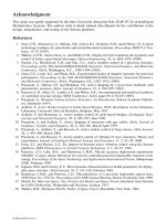
equilibrium. To show the difference between ZMP and CoP, let us consider the dynamically
unbalanced single-support situation (the mechanism as a whole rotates about the foot edge and
overturns) illustrated in Figure 27.2, which is characterized by a moment about CoP that could not
be balanced by the sole reaction forces. The reaction moment that can be generated between the
foot and the ground is limited due to the unilateral contact between each sole and the floor. The
intensity of balancing moments depends on the foot dimension. Obviously, it is easier for a person
with larger sole to balance the gait. The dynamic motion moments in specific cases may exceed
the limit, causing the foot to leave the ground. In spite of the existence of a nonzero supporting
area (soft human/humanoid foot), reaction forces cannot balance the system in such a case. The
way in which this situation in human/humanoid gait can occur will be considered later. As is clear
from Figure 27.2, the CoP and the ZMP do not coincide in this case. Using an analogy to fluid
dynamics, we could determine CoP as the center of pressure distribution (e.g., obtained by a pressure
mate). It should be mentioned that in regular human gait, in a dynamic transition phase (e.g., heel
strike and toe off), it is difficult to estimate CoP on the basis of force plate measurements.
However, ZMP, even in the case illustrated in Figure 27.2, can be uniquely determined on the
basis of its definition. Assuming that both reaction force and unbalanced moment are known, we
can mathematically replace the force–moment pair with a pure force displaced from the CoP. In
this situation, however, the ZMP and the assigned reaction force have a pure mathematical/mechan-
ical meaning (obviously, the ZMP does not coincide with the CoP) and the ZMP does not represent
a physical point. However, the ZMP location outside the support area (determined by the vector
in Figure 27.2) provides very useful information for gait balancing. The fact that ZMP is instanta-
neously on the edge or has left the support polygon indicates the occurrence of an unbalanced
−
r
R −
r
M
CoP
r
R
r
M
CoP
ZMPCoP
CoP
h
×+
()
=
rr
RM 0
r
M
CoP
h
()
= 0
ZMPCoP = 0
ZMP CoP≡
r
r
8596Ch27Frame Page 732 Tuesday, November 6, 2001 9:37 PM
© 2002 by CRC Press LLC
moment that cannot be compensated for by foot reaction forces. The distance of ZMP from the
foot edge provides the measure for the unbalanced moment that tends to rotate the human/humanoid
around the supporting foot and, possibly, to cause a fall. When the system encounters such a
hazardous situation, it is still possible by means of a proper dynamic corrective action of the biped
control system to bring ZMP into the area where equilibrium is preserved. To avoid this, a fast
rebalancing by muscles or actuator actions (change of dynamic forces acting on the body) is needed.
Several approaches to realization of this action have been discussed.
13
On the basis of the above discussion, it is obvious that generally the ZMP does not coincide
with the CoP
. (27.11)
The CoP may never leave the support polygon. However, the ZMP, even in the single-support
gait phase, can leave the polygon of the supporting foot when the gait is not dynamically balanced
by foot reaction forces, e.g., in the case of a nonregular gait (even in the case of a degenerative
gait). Hence, ZMP provides a more convenient dynamic criterion for gait analysis and synthesis.
The ZMP outside the support polygon indicates an unbalanced (irregular) gait and does not
represent a physical point related to the sole mechanism. It can be referred to as imaginary ZMP
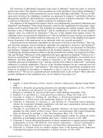
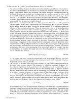
(IZMP). Three characteristic cases for the nonrigid foot in contact with the ground floor, sketched
in Figure 27.3, can be distinguished. In the so-called regular (balanced and repetitive) gait, the
ZMP coincides with CoP (Figure 27.3a). If a disturbance brings the acting point of the ground
reaction force to the foot edge, the perturbation moment will cause rotation of the complete biped
locomotion system about the edge point (or a very narrow surface, under the assumption that the
sole of the shoe is not fully rigid) and overturning (Figure 27.4). In that case we speak of IZMP,
whose imaginary position depends on the intensity of the perturbation moment (Figure 27.3b).
However, it is possible to realize the biped motion, for example, on the toe tips (Figure 27.3c) with
special shoes having pinpoint areas (balletic locomotion), while keeping the ZMP position within
the pinpoint area. Although it is not a regular (conventional, ordinary) gait, the ZMP also coincides
with CoP in that case.
FIGURE 27.2
Action/reaction forces at CoP and ZMP (irregular case).
ZMP CoP≠
8596Ch27Frame Page 733 Tuesday, November 6, 2001 9:37 PM
© 2002 by CRC Press LLC
Because of foot elasticity and the complex form of the supporting area, the ZMP displacements
outside the safe zone (Figure 27.2) in human locomotion are much more complex and difficult to
model. Even in a regular human gait, ZMP leaves the support polygon dynamically during the
transition from the single- to double-support phase, providing a smooth dynamic locomotion. The
implementation of such gait patterns in humanoids with simple rigid feet is not practically possible.
In the double-support phase, and even more during transition from the single to the double phase,
the ZMP leaves the foot-supporting polygon. Stable dynamic equilibrium in the double-support
phase is characterized by the ZMP location within the enveloping polygon between the two feet.
13
FIGURE 27.3
The possible relative positions of ZMP and CoP: (a) dynamically balanced gait, (b) unbalanced
gait (the system rotates about the foot-edge and overturns), and (c) intentional foot-edge equilibrium (balletic
locomotion).
FIGURE 27.4
Imaginary ZMP in unbalanced human gait.
8596Ch27Frame Page 734 Tuesday, November 6, 2001 9:37 PM
© 2002 by CRC Press LLC
The extent of ZMP dislocation from the enveloping polygon also provides a practical measure for
the unbalanced moments. In previous works
13
our attention has mainly been focused on the problems
of biped design and nominal motion synthesis, as well as stability analysis and biped dynamic
control that will prevent the ZMP excursions close to the edges of the supporting polygon in spite
of various disturbances and model uncertainties. Due to limitations of the sensory and control
systems, the occurrence of a new unpowered joint (ZMP at the edges of the support polygon) has
been considered as critical and undesirable in the past.
Hence, the situation when ZMP can arbitrarily be located in the foot plane was practical in
designing the biped foot dimensions and nominal motion synthesis. When the ZMP approaches
critical areas or even abandons the support polygon (Figure 27.3), balancing is focused primarily
on compensating for the unbalanced dynamic moment using the posture control. One way of
overcoming such critical situation is to switch to a new nominal trajectory that is closest to the
momentary system state.
5
These nominals are synthesized to bring the system back to the stationary
state and enable gait continuation. To do this, it is not necessary to have information about exact
intensity of the disturbance moment. For such an approach (which is very close to the human
behavior in similar situations), it suffices to detect the occurrence of such hazardous situations.
Thus, there is no need for on-line computation of the IZMP location for the purpose of biped
control. For these reasons the IZMP location has not gained more practical importance. However,
the recent development of powerful control and sensory systems and the fast expansion of humanoid
robots gives a new significance to the IZMP, particularly in rehabilitation robotics. The consideration
of ZMP locations, including also the areas outside the supporting foot sole, becomes essential for
rehabilitation devices.
12
27.2 Modeling of Biped Dynamics and Gait Synthesis
The synthesis of the motion of humanoid robots requires realization of a human-like gait. There are
several possible approaches, depending on the type of locomotion activity involved. It should be kept
in mind that the skeletal activity of human beings is extremely complex and involves many automated
motions. Hence, the synthesis of the artificial locomotion–manipulation motion has complexities related
to the required degree of mimicking of the corresponding human skeletal activity.
If, however, we concentrate on the synthesis of a regular (repeatable) gait, then it is natural to
copy the trajectories of the natural gait and impose them onto the artificial (humanoid) system. Of
course, the transfer of trajectories (in this case of the lower limbs) from a natural to an artificial
system can be realized with a higher or lower degree of similarity to the human gait. Hence, the
anthropomorphism of artificial gait represents a serious problem. To explain the practical approach
to solving this problem, let us assume we have adopted one of the possible gait patterns. By
combining the adopted (prescribed) trajectories of the lower limb joints (method of prescribed
synergy
1,2,5,13
) and the position (trajectory) of ZMP using the semi-inverse method,
2,5,13
it is possible
to determine the compensation motion of the humanoid robot from the moments about the corre-
sponding axes for the desired position of the ZMP (or ZMP trajectory). The equilibrium conditions
can be written also for the arm joints. In fact, the unpowered arm joints represent additional points
where moments are known (zero). These supplementary moment equations about the unpowered
arm axes yield the possibility of including passive arms in the synthesis of dynamically balanced
humanoid gait.
27.2.1 Single-Support Phase
Let us suppose the system is in single-support phase and the contact with the ground is realized
by the full foot (Figure 27.5). It is possible to replace all vertical elementary reaction forces by the
resultant force R
V
. Only regular gait will be considered, and the ZMP position has to remain within
the support area (polygon).
8596Ch27Frame Page 735 Tuesday, November 6, 2001 9:37 PM
© 2002 by CRC Press LLC
The basic idea of artificial synergy synthesis is that the law of the change of total reaction force
under foot is known in advance or prescribed. The prescribed segments of the dynamic character-
istics which restrict the system in a dynamic sense are called dynamic connections. If a certain
point represents the ZMP and the ground reaction forces is reduced to it, then the moment
should be equal to zero. The vector always has a horizontal direction and, hence, two dynamic
conditions have to be satisfied: the projection of the moment on the two mutually orthogonal axes
X and Y in the horizontal plane should be equal to zero.
(27.12)
As far as friction forces are concerned, it is a realistic assumption that the friction coefficient is
sufficiently large to prevent slippage of the foot over the ground surface. Thus, it can be stated that
their moment with respect to the vertical axis V is equal to zero:
. (27.13)
The axis V can be chosen to be in any place, but if it passes through the ZMP, then the axes X,
Y, and V constitute an orthogonal coordinate frame, and V will be denoted by Z. The external
forces acting on the locomotion system are the gravity, friction, and ground reaction forces. Let us
reduce the inertial forces and moments of inertial forces of all the links to the ZMP and denote
them by and , respectively. The system equilibrium conditions can be derived using D’Ale-
mbert’s principle and conditions (27.12) can be rewritten as:
, (27.14)
where is the total moment of gravity forces with respect to ZMP, while and are unit
vectors of the
x
and
y
axes of the absolute coordinate frame. The third equation of dynamic
connections, Equation (27.13), becomes:
(27.15)
where is a vector from ZMP to the piercing point of the axis V through the ground surface;
is a unit vector of the axis V.
Let us adopt the relative angles between two links to be the generalized coordinates and denote
them by . Suppose the mechanism foot rests completely on the ground, so that the angle is zero,
. The inertial force and the moment , in general, can be represented in the linear forms
of the generalized accelerations and quadratic forms of generalized velocities:
FIGURE 27.5
Longitudinal distribution of pressure on the foot and ZMP position.
r
R
V
r
M
r
M
X
M
= 0
Y
M
= 0
V
M
= 0
r
F
F
M
r
G
F
X
M
M
e
(
)
r
r
r
+⋅=0
G
F
Y
M
M
e
(
)
r
r
r
+⋅=0
r
M
G
r
e
X
r
e
Y
F
V
M
Fe
(
)
r
r
r
r
+
×
⋅=
ρ
0
r
ρ
v
e
r
i
q
0
0
q
≡
r
F
r
M
F
8596Ch27Frame Page 736 Tuesday, November 6, 2001 9:37 PM
© 2002 by CRC Press LLC
, k = 1, 2, 3
, k = 1, 2, 3 (27.16)
where the coefficients (k = 1, 2, 3; and = 1, …, n; j = 1, … n) are the functions of the
generalized coordinates, and and (k = 1, 2, 3) denote projections of the vectors and
onto the coordinate axes. By introducing these expressions into Equations (27.14) and (27.15) one
obtains:
(27.17)
where the superscripts
x
and
y
denote the components in direction of the corresponding axis.
If the biped locomotion system has only three DOFs, the trajectories for all angles can be
computed from Equation (27.17). If the system has more than three DOFs (and this is actually the
case), the trajectories for the rest (n-3) coordinates should be prescribed in such a way to ensure
the desired legs trajectories (for example, measured from the human walk). The trajectories for this
part of the system are prescribed, while the dynamics of the rest of the system (i.e., the trunk and
arms) are determined in a such a way to ensure the dynamic balance of the overall mechanism.
The set of coordinates can be divided in two subsets: one containing all the coordinates whose
motion is prescribed, denoted as , and the other comprising all the coordinates whose motion
is to be defined using the semi-inverse method,
1,13
denoted as . Accordingly, the condition (27.17)
becomes:
, k = 1, 2, 3 (27.18)
where and (k = 1, 2, 3) are the vector coefficients dependent on and , whereas the
vector (k = 1, 2, 3) is a function of , , , and . Since the gait is symmetric, the
repeatability conditions can be written in the form:
1,13
,
where the sign depends on the physical nature of the appropriate coordinates and their derivatives;
is the duration of one half-step. As the motion of the prescribed part of the mechanism has
been already defined (repeatability conditions are implicitly satisfied), the repeatability conditions:
, (27.19)
k
i
k
i
n
i
i
n
ij
k
j
n
ij
F
a
q
b
=
∑
⋅+
∑∑
⋅
===111
˙˙ ˙ ˙
F
k
i
k
i
n
i
i
n
ij
k
j
n
ij
M
c
q
d
=
∑
⋅+
∑∑
⋅
===111
˙˙ ˙ ˙
i
k
ij
k
i
k
ij
k
abcd
,,,
k
F
F
k
M
r
F
r
M
F
G
x
i
i
n
i
i
n
ij
j
n
ij
M
e
c
q
d
r
r
⋅+
∑
⋅+
∑∑
⋅=
===
1
11
1
1
0
˙˙ ˙ ˙
G
y
i
i
n
i
i
n
ij
j
n
ij
M
e
c
q
d
r
r
⋅+
∑
⋅+
∑∑
⋅=
===
2
11
2
1
0
˙˙ ˙ ˙
i
i
n
i
i
n
ij
ij
n
ij
x
i
i
n
i
i
n
ij
i
n
ii
y
i
i
n
i
i
n
ij
j
n
ij
c
q
d
a
q
b
a
q
b
3
11
32
11
2
1
1
11
1
1
0
=== = == ===
∑
⋅+
∑∑
⋅+
∑
⋅+
∑∑
⋅−
∑
⋅+
∑∑
⋅=
˙˙ ˙ ˙
(
˙˙ ˙ ˙
)(
˙˙ ˙ ˙
)
ρρ
i
q
0i
q
x
i
q
i
k
i
n
xi
i
n
ij
k
j
n
xi xj
k
c
q
d
g
===
∑
⋅+
∑∑
⋅+=
111
0
˙˙ ˙ ˙
i
k
c
ij
k
d
0
q
x
q
k
g
0
q
0
˙
q
0
˙˙
q
x
q
ii
T
()0
2
=±
ii
T
˙
()
˙
0
2
=±
T 2
()
xi xi
T
()0
2
=±
xi xi
T
˙
()
˙
0
2
=±
8596Ch27Frame Page 737 Tuesday, November 6, 2001 9:37 PM
© 2002 by CRC Press LLC
for the rest of the mechanism are to be added to the original set of equations describing the
mechanism motion.
The system of Equation (27.18), together with the conditions (27.19), enables one to obtain the
necessary trajectories of the coordinates , i.e., to carry out compensation synergy synthesis. After
the synergy synthesis is completed, the driving torques that force the system to follow the nominal
trajectories have to be computed.
27.2.2 Double-Support Phase
In the double-support phase, both mechanism feet are simultaneously in contact with the ground.
The kinematic chain playing the role of the legs is closed, i.e., the unknown reaction forces to be
determined act on both ends.
The procedure for the synergy synthesis is in the most part analogous to that for the single-
support phase. Let the position of the axis V be selected within the dashed area in Figure 27.6.
Then, by writing the equilibrium equations with respect to the three orthogonal axes passing through
ZMP and setting the sum of all the moments of external forces to zero, the compensating movements
for the corresponding part of the body can be computed.
The next problem is how to choose the position of the axis V with respect to the ZMP. The
information on ZMP and axis V is insufficient for computation of the driving torques. For this
reason, it is necessary to provide some additional relations concerning the ground reaction force.
The total reaction force under one foot can be expressed as a sum of three reaction forces and
moment components in the direction of coordinate axes. The components and can be equal
to zero since the vertical forces on the diagram are of the same sign. The third component
should also be equal to zero, according to the following consideration. Generally speaking, friction
forces can produce moments, but in synergy synthesis, the moment should also be equal to
zero. Consequently, if the moments of friction forces are generated, they should be of the opposite
sign under each foot. However, these moments do not affect the system motion but only load the
leg drives and joints additionally. Because of that, it is reasonable to synthesize the gait in such a
way to reduce each of these moments to zero. Thus it can be assumed that total moments of reaction
forces under each foot are equal to zero:
(27.20)
where the subscripts
a
and
b
denote the left and right foot, respectively.
Characteristics of the friction between the foot and the ground can be represented by a friction
cone (Figure 27.7). If the total ground reaction force is within the cone of the angle , its
horizontal component (i.e., friction force) will be of sufficient intensity to prevent an unwanted
horizontal motion of the supporting foot over the ground surface. This can be expressed as:
13
FIGURE 27.6
Double-support phase.
xi
q
X
M
Y
M
V
M
V
M
ab
MM
rr
==0
r
R 2γ
8596Ch27Frame Page 738 Tuesday, November 6, 2001 9:37 PM
© 2002 by CRC Press LLC
(27.21)
where µ is the friction coefficient of the surfaces in contact. Thus, it is reasonable to distribute the
horizontal components of ground reaction forces per foot proportionally to the normal pressure.
The vertical components are inversely proportional to the distances between the ZMP and the
corresponding foot, so:
(27.22)
Then, from Equation (27.21) the relation:
4,13
(27.23)
holds for the horizontal components, where and are the friction forces under the corresponding
foot (Figure 27.8). On the basis of similarity of the triangles
∆
OAD and
∆
OBC, it can be concluded
that the relation (27.23) does not depend on the direction of the force (i.e., the distances and
), but only on the distances between the feet, and . Thus, in order to have friction forces
divided in proportion to the vertical pressures, a necessary and sufficient condition is that the axes
and pass through the ZMP. Then, for synergy synthesis in the double-support phase, the
following vector equation holds:
(27.24)
where is a radius vector from the ZMP to the gravity center of the
i-
th link and and are
the inertial force and corresponding moment of the
i-
th link reduced to its center of gravity.
When the synthesis of the compensating laws of motion is completed, it is possible to determine
the total horizontal and vertical reactions:
, (27.25)
FIGURE 27.7
Friction cone.
xy
v
RR
R
tg
rr
r
+
≤=γµ
a
b
v
R
v
R
b
a
r
r
l
l
=
a
b
b
a
T
T
r
r
l
l
=
r
T
a
r
T
b
r
T
′
l
a
′
l
b
a
l
b
l
′
l
a
′
l
b
i
i
ii
i
n
r
G
FM
r
r
rr
×+
()
+
()
∑
=
=1
0
r
r
i
r
F
i
r
M
i
Z
iZ
i
i
n
R
F
G
=− +
()
∑
=
r
r
1
rr
r
r
r
TF
e
F
e
iX
X
iY
Y
i
n
=⋅+⋅
()
∑
=1
8596Ch27Frame Page 739 Tuesday, November 6, 2001 9:37 PM
© 2002 by CRC Press LLC
where is the projection of onto the vertical axis and and are projections onto the
axes X and Y, respectively. Here, the axis Z corresponds to the vertical axis (previously denoted
by V) passing through ZMP. The axes X, Y, and Z constitute the absolute orthogonal coordinate
frame. Furthermore, the relations and are obvious, and they, together with
the relations:
(27.26)
extend the possibility of defining the vertical reactions and , as well as the friction forces
and . The and are the vectors from the ZMP (denoted by 0) to the centers of the
corresponding supporting surfaces A and B, respectively.
27.2.3 Biped Dynamics
The active spatial mechanism for realization of the artificial anthropomorphic gait belongs to the
class of complex kinematic chains, as shown in Figure 27.9. During walking, the kinematic chain
representing the legs changes its configuration from open to closed,
4,13
in the single- and double-
support phases, respectively. Each phase involves a different procedure for forming dynamic
equations, but it is based on the well-known procedure for dynamic modeling of simple open
kinematic chains for robotic manipulators. This procedure enables us to obtain the following
expression:
13,14
(27.27)
where P = [P
1
, …, P
n
] is a vector of driving moments at the joints, is the
n
×
n
inertial
matrix, is the
n
×
1 vector of Coriolis, centrifugal, and gravity forces, q = [q
1
, …, q
n
] is
a vector of joint coordinates, and
θ
= [
θ
1
, …,
θ
n
] is a geometric and dynamic parameter vector.
In the case of complex kinematic chains, the system has at least one link (branching link)
belonging to more than two kinematic chains. Calculation of the elements of the matrix H and the
vector h of complex kinematic chains can be carried out by introducing the corresponding number
FIGURE 27.8 Determination of total friction force.
iZ
F
r
i
F
r
iX
F
r
i
Y
F
r
rrr
TTT
ab
=+
rrr
RRR
ab
=+
a
a
b
b
TT
r
l
r
r
l
r
×
+× =0
a
a
b
b
RR
r
l
r
r
l
r
×
+× =0
a
R
r
b
R
r
a
T
r
b
T
r
a
r
l
b
r
l
P
Hq q hqq=
()
⋅+
()
,
˙˙
,
˙
,θθ
Hq,θ
()
hqq,
˙
,θ
()
8596Ch27Frame Page 740 Tuesday, November 6, 2001 9:37 PM
© 2002 by CRC Press LLC
of series of “+” joints.
4,13
A series of “+” joints is formed in such a way that in the case of chain
rupture at a certain “+” joint, the j-th link should remain in the external part (not connected to the
support) of the mechanism. In the course of forming differential equations, the inertial force and
moment of the j-th mechanism link are reduced to its own “+” joint only, and the following procedure
is possible: and (total external force and moment) corresponding to the j-th link are
successively reduced to all “+” joints going from the j-th link toward the support. After projecting
and onto the axis of the i-th joint, the resulting quantities denoted by and can
be calculated in the following way:
4,13
, (27.28)
where is the unit vector of the i-th joint axis, and is the radius vector from the i-th joint to
the j-th link center of mass, while and are the corresponding vector coefficients. Note that
the angular ( ) and linear ( ) accelerations of the i-th link can be expressed as:
,
where . The and are the vector coefficients depending on the generalized
coordinates, while the vector coefficients and depend on the generalized coordinates and
velocities. Then, we have:
4,13
, , ,
with , , and
where (j = 1, 2, 3) denotes the j-th component of the vector , denotes the axes of the
i-th (local) coordinate frame, i.e., the frame attached to the i-th link, and is the j-th component
of the i-th link inertia tensor defined with respect to the local coordinate frame associated to each
link of the kinematic chain.
The components of matrix H and vector h are obtained by summing the corresponding values
from Equation (27.28) with respect to all series of “+” joints:
FIGURE 27.9 Complex kinematic chain.
j
u
F
r
j
u
M
r
j
u
F
r
j
u
M
r
∆
ik
j
H
∆
i
j
h
∆
ik
j
i
jk
ji
jk
H
e
b
r
a
=
−
+×
()
r
r
r
r
∆
i
j
i
ji j
o
jj
o
h
e
raGb=
−
×+
()
+
()
r
rr
r
r
i
e
r
ji
r
r
r
a
r
b
i
r
ε
i
w
r
i i ii i
q
r
rr r
ε
αα α
=
[]
+
1
0
00
˙˙
i
iii i
w
q
r
rr r
=
[]
+
1
0
00
ββ β
˙˙
˙˙
˙˙
, ,
˙˙
q
n
=
[]
1
ij
α
ij
β
i
0
r
α
i
0
r
β
ij
iij
a
m
r
r
=− β
i
ii
a
m
0
0
r
r
=− β
ij
iij
b
T
r
r
=− α
j
ii i
b
T
0
0
r
r
r
=− +αλ
TQJ
iii
=
∑
=
ll
l 1
3
Qqqqqqq
iiiiiiilllllll
rr r
=
[]
11 22 33
i
i
i
i
i
i
ii
i
i
i
i
ii
i
i
i
i
ii
Q
JJ
JJ
JJ
r
r
r
r
r
r
r
r
r
r
r
r
r
λ
ωω
ωω
ωω
=
⋅⋅ −
⋅⋅−
⋅⋅ −
()()( )
()()( )
()()( )
23
23
31
31
12
12
q
i
j
l
r
l
q
i
i
q
l
r
ij
J
8596Ch27Frame Page 741 Tuesday, November 6, 2001 9:37 PM
© 2002 by CRC Press LLC
, (27.29)
Figure 27.10 illustrates a branching link that has three kinematic pairs and is a constituent of
two series of “+” joints. The topological structure of the complex chain can be represented by the
matrix MS. Each row of this matrix contains ordinal numbers of the corresponding series of “+”
joints. The element MS(i,j) is the j-th joint in the i-th series of “+” joints. In addition, for each
series of “+” joints, the ordinal number of the initial joint is also defined. The initial joint of the
i-th series of “+” joints is the first joint of the i-th series differing from joints of the (i–1)-th series
of “+” joints. The initial joint of the first series of “+” joints is MS(1,1). For the first link appearing
in the first series of “+” joints, the matrix should be known. is a transformation matrix
between the reference frame representing ground floor (or basis) and the first link of the kinematic
chain resting on the ground floor. It is convenient to place the reference frame just at the contact
point. Then, if a fixed support serves as a basis, the matrix is a unit matrix. If we proceed to
another chain, then the matrix ( is a transformation matrix of the i-th link coordinate frame
into the reference frame) should be either stored or formed on the basis of the procedure for forming
dynamic equations of motion for open kinematic chains. The transformation matrix of the branching
link serves to calculate the vectors and . Information is needed on the branching link velocities
( ) and accelerations ( ) and the vector coefficients , and .
4,13
All support vectors are
equal to zero. These quantities for the mobile branching link should be stored when the preceding
chain is analyzed.
To consider the biped dynamics in the double-support phase (Figure 27.11), an equivalent open
kinematic chain should be employed. Let us suppose that the terminal link of the equivalent chain
does not coincide with the basic link (Figure 27.12). It is possible to determine the translational
( ) and angular ( ) displacements yielding the coincidence of the two coordinate systems
and . Since we consider an open chain equivalent to the closed chain in the dynamic analysis,
it is possible to use the same basic procedure as for the open chain.
4,13
Thus, the algorithm should
be supplied with an iterative procedure to calculate the position and additional velocities of the
first chain. The procedure is repeated until the closure conditions are satisfied.
27.2.4 Example
The nominal dynamics synthesized for the biped locomotion mechanism shown in Figures 27.13 and
27.14 consists of 14 links and 14 revolute joints of the 5-th class for the single-support phase only.
Links 5 and 10 are branching links. In the course of motion, the hands are fixed on the chest of the
FIGURE 27.10 Branching link of a complex kinematic chain.
ik
j
ik
j
j
HH
=
∑
∆
()
i
j
i
j
j
hh
=
∑
∆
()
o
o
Q
o
o
Q
o
o
Q
i
o
Q
i
o
Q
r
r
r
e
r
v
r
w
r
r
r
α
β
α
,,
o
o
r
β
∆
r
ρ ∆
r
σΨ
′
Ψ
© 2002 by CRC Press LLC
mechanism. This structure can be split into three kinematic chains containing joints 1 through 8, 9
through 12, and 13 and 14, in the first, second, and third chains, respectively. The topological structure
of the complex kinematic chain can be represented by a series of “+” joints in a matrix form:
.
Table 27.1 shows numerical values for the mechanical part of the mechanism. The prescribed
portion of the mechanism motion is adopted for joints 1 through 8, i.e., for the first chain. This
part of the synergy (prescribed synergy) is defined on the basis of the human gait measurements
shown in Figure 27.15. A set of prescribed ZMP trajectories for the single-support gait phase is
given in Figure 27.16 and the compensation has been synthesized for and (Figure 27.17) to
ensure dynamic equilibrium of the mechanism during the motion, in both the sagittal and frontal
planes (Figure 27.18).
27.3 Control Synthesis for Biped Gait
Hierarchy is a basic principle on which control of large scale systems is generally based. This holds
true for robots as well. The hierarchical organization of the control system is most often vertical,
so that each control level deals with wider aspects of the overall system behavior than the lower
level.
15-18
A higher control level always refers to the lower ones, and it controls system parameters
that vary more slowly. A higher level communicates with a lower level, giving it instructions and
receiving from it relevant information required for decision making. After obtaining the information
from a lower level, each level makes decisions taking into account decisions obtained from higher
levels and forwards them to the lower levels for execution.
27.3.1 Synthesis of Control with Limited Accelerations
Control synthesis is performed in two steps: (a) nominal regimes, and (b) perturbed regimes. For
nominal regimes, the control is computed on the basis of the complete (nonlinear) model with the
FIGURE 27.11 The anthropomorphic mechanism
in double-support position.
FIGURE 27.12 Terminal link of the equivalent
chain.
MS =
123456 7 8 0
1 2 3 4 5 9 10 11 12
1 2 3 4 5 9 10 13 14
9
q
10
q
8596Ch27Frame Page 743 Tuesday, November 6, 2001 9:37 PM
© 2002 by CRC Press LLC
permanent requirement of satisfying dynamic equilibrium conditions for the overall mechanism.
This control should enable the system (in the absence of disturbance) to follow the nominal
trajectories. For perturbed regimes, the control should force the state vector to its nominal value,
i.e., to the nominal programmed trajectory. The action should be smooth, with no significant change
in link acceleration, to keep its influence on the unpowered DOFs within an acceptable range.
13,19
Let us consider the overall system model defined as:
Assume that the part of the system corresponding to powered DOFs can be rearranged as a set
of subsystems coupled via the term :
,
FIGURE 27.13 Mechanical scheme of the anthro-
pomorphic mechanism with fixed arms. FIGURE 27.14 Notation of vectors.
ij
r
,
˜
r
Sx Ax BxNu
i
:
˙
ˆ
ˆ
=
()
+
() ()
a
i
S
c
i
c
i
f
P
⋅
()
a
i
S
:
c
i
c
i
c
i
c
ii
c
i
c
i
x
A
xb
N
u
f
P
˙
()=+ +
∀∈i
I
1
8596Ch27Frame Page 744 Tuesday, November 6, 2001 9:37 PM
© 2002 by CRC Press LLC
where is the subsystem matrix, whereas and are distribution vectors of
the input control signal and force, respectively, is the subsystem state vector, and
are the scalar values of control input and generalized force of the i-th subsystem, ,
, is the nonlinearity of the amplitude saturation type.
Let the nominal trajectory , and the nominal control ,
be introduced in such a way to satisfy:
, . (27.30)
TABLE 27.1 Kinematic and Dynamic Parameters of the Mechanism
Mass
Moment of Inertia (kgm
2
)
Distance of the Axes Centers of Joints from the Link Center Joint Unit
Link (kg) J
X
J
Y
J
Z
(m) Axes
1 0.0 0.0 0.0 0.0
= (0,0,0.0001)
T
; = (0,0,-0.0001)
T
= (1,0,0)
T
2 1.53 0.00006 0.00055 0.00045
= (0,0,0.030)
T
; = (0,0,-0.070)
T
= (0,1,0)
T
3 3.21 0.00393 0.00393 0.00038
= (0,0,0.210)
T
; = (0,0,-0.210)
T
= (0,1,0)
T
4 8.41 0.01120 0.01200 0.00300
= (0,0,0.220)
T
; = (0,0,-0.220)
T
= (0,1,0)
T
5 6.96 0.00700 0.00565 0.00627
= (0,0.135,0.1)
T
; = (0,-0.135,0.1)
T
; = (0,0,-0.05)
T
= (0,1,0)
T
6 8.41 0.01120 0.01200 0.00300
= (0,0,–0.220)
T
; = (0,0,0.220)
T
;
= (0,–1,0)
T
7 3.21 0.00393 0.00393 0.00038
= (0,0,–0.210)
T
; = (0,0,0.210)
T
= (0,–1,0)
T
8 1.53 0.00006 0.00055 0.00045
= (0,0,–0.070)
T
= (0,–1,0)
T
9 0.0 0.0 0.0 0.0
= (0,0,0.0001)
T
; = (0,0,-0.0001)
T
= (0,1,0)
T
10 30.85 0.15140 0.13700 0.02830
= (0,0,0.34)
T
; = (0,0.2,-0.06)
T
; = (0,-0.2,-0.06)
T
= (1,0,0)
T
11 2.07 0.00200 0.00200 0.00022
= (0,0,–0.154)
T
; = (0,0,0.154)
T
= (1,0,0)
T
12 1.14 0.00250 0.00425 0.00014
= (0,0,–0.132)
T
= (1,0,0)
T
13 2.07 0.00200 0.00200 0.00022
= (0,0,–0.154)
T
; = (0,0,0.154)
T
= (–1,0,0)
T
14 1.14 0.00250 0.00425 0.00014
= (0,0,-0.132)
T
= (–1,0,0)
T
FIGURE 27.15 Synergy for walking upon level ground.
˜
,
r
r
11
˜
,
r
r
12
˜
r
e
1
˜
,
r
r
22
˜
,
r
r
23
˜
r
e
2
˜
,
r
r
33
˜
,
r
r
34
˜
r
e
3
˜
,
r
r
44
˜
,
r
r
45
˜
r
e
4
˜
,
r
r
55
˜
,
r
r
56
˜
,
r
r
59
˜
r
e
5
˜
,
r
r
66
˜
,
r
r
67
˜
r
e
6
˜
,
r
r
77
˜
,
r
r
78
˜
r
e
7
˜
,
r
r
88
˜
r
e
8
˜
,
r
r
99
˜
,
r
r
910
˜
r
e
9
˜
,
r
r
10 10
˜
,
r
r
10 11
˜
,
r
r
10 13
˜
r
e
10
˜
,
r
r
11 11
˜
,
r
r
11 12
˜
r
e
11
˜
,
r
r
12 12
˜
r
e
12
˜
,
r
r
13 13
˜
,
r
r
13 14
˜
r
e
13
˜
,
r
r
14 14
˜
r
e
14
c
i
nxn
A
R
ii
∈
c
i
n
b
R
i
∈
c
i
n
f
R
i
∈
c
i
n
x
R
i
∈
i
u
R∈
1
c
i
P
R∈
1
iI∈
1
Iii m
1
12==
}
{
, , , ,
i
Nu(
)
c
o
x
xxx x
c
o
c
o
c
o
c
om
T
TT T
=…
()
12
,,,
o
u
o
T
u
o
u
o
u
om
u
=
12
, , ,
a
i
S
:
c
oi
c
i
c
oi
c
ioi
c
i
c
oi
x
A
xb
N
u
f
P
˙
()=+ +
∀∈i
I
1
8596Ch27Frame Page 745 Tuesday, November 6, 2001 9:37 PM
© 2002 by CRC Press LLC
Then, the model of subsystem deviation from the nominal is considered in the form:
, . (27.31)
The purpose of the synthesis of disturbance-compensating control is to force the system
deviation , (i = 1, 2, …, m) to zero, to maintain the overall system dynamic balance.
We shall synthesize the local controller for the i-th actuator, i.e., for the subsystem whose
model of state deviation around the nominal trajectory is given by Equation (27.31). We want to
define the controller for this subsystem that will reduce the state deviation to zero, but in
doing so we want to prevent the appearance of very high accelerations. Therefore, we shall
synthesize a controller that will ensure the acceleration of the corresponding joint be limited.
We start with the simple problem of the second order linear system with limited accelerations.
13,19
Let us consider the classical time-minimum problem. Let the system be described by:
(27.32)
FIGURE 27.16 Set of ZMP trajectories for the single-support gait phase.
FIGURE 27.17 Compensating DOF in the frontal (a) and sagittal (b) planes.
c
i
c
i
c
i
c
i
i
c
i
c
i
x
Ax
b
N
u
f
P∆
∆∆
∆
˙
()=+ +
∀∈i
I
1
∆u
()
c
i
x∆
a
i
S
c
i
x
t
∆
()
∆
i
q
˙˙
∆∆
1
2
i
i
q
t
q
t
˙
() ()=
∆
2
i
i
q
t
u
t
˙
() ()
*
=
i
i
u
t
*
()≤
Ω
8596Ch27Frame Page 746 Tuesday, November 6, 2001 9:37 PM
© 2002 by CRC Press LLC
with the initial conditions and , where , , and .
The value should be computed in such a way to ensure that the system (27.32) returns from
to the point (0, 0) in a minimal time interval.
Therefore, such a solution of Equation (27.32) should be obtained that the functional
is at minimum, where defines an unspecified time interval. Such types of problems are well
known, and for this particular case ( ), its solution is given by the expression:
. (27.33)
We shall apply this solution to control one single actuator, i.e., the subsystem associated with
the i-th joint. Let us suppose the mechanism is powered by DC motors whose models are given in
the form (the state vector
. (27.34)
FIGURE 27.18 Compensating movements for the single-support gait upon level ground for T = 1.5, S = 0.6, and
ZMP laws from Figure 27.16.
∆
1
0
i
i
q
()=
α
∆
2
0
i
i
q
()=β
i
R
Ω
∈
1
∆
1
1
i
q
R
∈
∆
2
1
i
q
R
∈
i
u
t
*
()
i
i
α
β,
()
Jdt
T
=
∫
0
*
*
TR
∈
1
i
Ω
≠1
i
i
i
ii
i
i
i
i
i
i
i
ii
i
i
i
i
i
u
q
q
q
q
q
q
q
q
*
=
+< =
()
∧≤
−>
−
=
−
()
∧≥
Ω
∆
∆∆
Ω
∆
∆
Ω
∆
Ω
∆
∆∆
Ω
∆
∆
Ω
∆
if or
if or
1
22
1
2
2
2
1
22
1
2
2
2
22
0
22
0
a
i
S
c
i
i
i
R
i
T
x
q
q
i∆
∆
∆
∆
=(,
˙
,):
i
i
R
i
ii
ii
i
i
R
i
c
i
c
i
c
i
i
q
q
i
aa
aa
q
q
i
f
P
b
u
∆
∆
∆
∆
∆
∆
∆∆
˙
˙˙
˙
˙
*
=
+
+
01 0
0
0
0
0
0
0
22 23
32 33
8596Ch27Frame Page 747 Tuesday, November 6, 2001 9:37 PM
© 2002 by CRC Press LLC
From the second equation of (27.34) we can write:
(27.35)
where is replaced by the value of the allowed link acceleration from (27.33). Then,
in (27.35) is the corresponding rotor current, and its derivative can be computed from the following
expression:
(27.36)
where is the control sampling period. Now we can determine the control for Equation (27.34).
Let us assume that we want to limit acceleration of the actuator (joint) within the limits and
. Starting from the time-minimum control (Equation (27.33)) we can adopt the following
control. From the third equation of Equation (27.34) the compensation control signal for the i-th
actuator is
13
(27.37)
where the constant feedback gains are
,
, , (27.38)
where , , , are the elements of the corresponding matrix and vectors of the
actuator (27.34), and are the maximal and minimal values of the accelerations of the
i-th link. The feedback gains synthesized in this way have to ensure compensating movements such
that the accelerations do not exceed a certain predetermined limit. As a consequence, the induced
inertial forces will not cause an undesirable motion of the unpowered DOFs, i.e., the displacement
of ZMP out of a prescribed area. The proposed control law (27.37) consists of two parts: local
control and global control (concerning feedback with respect to from the rest of the system
upon the i-th subsystem). The term may be conditionally associated with global control,
although it is based upon local feedback information. The global control ( ) requires
information on the coupling acting upon the i-th subsystem.
27.3.2 Synthesis of Global Control with Respect to ZMP Position
The decentralized control defined by Equation (27.37) applied at the mechanism’s joints is not
sufficient to ensure tracking of internal nominal trajectories with the addition of the appropriate
behavior of the unpowered subsystem. An additional feedback must be introduced at one of the
powered joints to ensure satisfactory motion of the complete mechanism. The task of this feedback
is to reduce the destabilizing effect of the coupling acting upon the unpowered subsystems.
R
i
ii
i
c
i
c
i
i
i
ua
q
f
P
a
*
*
(
˙
)/
∆
∆
∆=− −
22 23
i
q∆
˙˙
i
u
*
R
i
i
*
∆
R
i
R
i
R
i
i
ii
t
∆
∆∆
∆
˙
/
*
=−
()
∆t
R
∈
1
min
i
Ω
max
i
Ω
i
i
L
i
i
L
i
i
L
R
i
i
G
c
i
i
G
u
k
q
k
q
kik
P
k
∆
∆∆∆∆=+++ +
123
4
5
˙
*
i
L
k
1
0=
i
L
iii
kaaa
td
2
22 23 32
=
−
−⋅⋅
()
∆ /
i
L
ii
ka a
td
3
23 33
1=− + ⋅
()
∆ /
i
G
c
i
k
f
d
4
=
−
/
i
G
i
kk
d
55
= /
i
i
i
ii
i
i
i
i
i
i
i
ii
i
i
i
i
i
k
q
q
q
q
q
q
q
q
5
2
2
05
05
0
05
05
0
=
<
−
=
()
∧<
>
−
=
−
()
∧>
max
min
.
˙˙
.
˙
˙
.
˙˙
.
˙
˙
Ω
∆
∆∆
Ω
∆
∆
Ω
∆
Ω
∆
∆∆
Ω
∆
∆
Ω
∆
if or
if or
d
a
b
t
i
c
i
=
23
∆
jk
i
a
c
i
b
c
i
f
max
i
Ω
min
i
Ω
∆
c
i
P
*
i
G
k
5
i
G
c
i
k
P
4
∆
*
8596Ch27Frame Page 748 Tuesday, November 6, 2001 9:37 PM
© 2002 by CRC Press LLC
Since a dominant role in system stability is played by the unpowered DOFs it is necessary to
reduce the destabilizing coupling effects acting upon them. Because the unpowered subsystem
cannot compensate for its own deviation from the nominal state, one of the powered subsystems
has to be chosen to accomplish it. As coupling of the subsystems is a function of control input
to the i-th subsystem , it is clear that a feedback from the subsystem to the inputs of
the subsystem should be introduced.
In dealing with bipeds,
13,20
where the unpowered DOFs are formed by contact of the feet and
the ground, it is possible to measure the ground reaction force with the aid of force sensors (at
least three) to determine the acting point of total vertical reaction force. For the known motion of
the overall mechanism, the ground reaction force (or force in double-support phase) is defined by
the intensity, direction, and position of the acting point on the foot. If force sensors A, B, and C
are introduced (Figure 27.19) and the system is performing gait, the measured values of vertical
reaction forces , , and correspond to their nominal values, and the nominal position of
ZMP can be determined. Measurement of the vertical reaction forces , , and when the
mechanism is performing gait in the presence of disturbances enables the determination of the
actual position of ZMP. If the nominal ZMP position corresponds to point 0, it can be written:
(27.39)
where , , and are the deviations of the corresponding measured forces from their
nominal values, is the total vertical reaction force, and and are the displacements of ZMP
from its nominal position. These displacements can be computed from Equation (27.39), provided the
sensor dispositions and vertical reaction forces are known. The actual position of the ZMP is the best
indicator of overall biped behavior, and we can use it to achieve a dynamically balanced motion. Our
aim is to synthesize such control that will ensure a stable gait. The primary task of the feedback with
respect to ZMP position is to prevent its excursion out of the allowable region, i.e., to prevent the
system from falling by rotation about the foot edge. If this is fulfilled, a further requirement imposed
is to ensure that the actual ZMP position is as close as possible to the nominal.
Our further discussion will be limited to biped motion in the sagittal plane, which means that
the ground reaction force position will deviate only in the direction of the x axis by . Figure 27.20
illustrates the case when the vertical ground reaction force deviates from the nominal position
0 by ; thus, the moment is a measure of the mechanism’s overall behavior.
In the same way we can consider the mechanism motion in the frontal plane. is
a measure of the mechanism’s behavior in the direction of the y axis. Let us assume the correction
of the acting point in one direction is done by the action at only one joint, arbitrarily selected
in advance. A basic assumption introduced for the purpose of simplicity is that the action at the
chosen joint will not cause a change in the motion at any other joint. If we consider only this
FIGURE 27.19 Disposition of the force sensors on the mechanism sole.
j
S
a
i
S
j
S
∆
i
u
a
i
S
A
R
B
R
C
R
A
R
B
R
C
R
s
RRMR
y
B
C
xz
()∆∆ ∆−==⋅
12
d
RR
d
RMR
x
B
CA
yz
()∆∆ ∆ ∆+− ==⋅
∆
A
R
∆
B
R
∆
C
R
z
R
∆x
∆y
∆x
z
R
∆x
z
ZMP
x
R
x
M
⋅=∆
z
ZMP
y
R
y
M
⋅=∆
z
R
8596Ch27Frame Page 749 Tuesday, November 6, 2001 9:37 PM
© 2002 by CRC Press LLC
action, the system will behave as if composed of two rigid links connected at the joint k, as presented
in Figure 27.20. In other words, the servo systems are supposed to be sufficiently stiff. In
Figure 27.20, two situations are illustrated: (case a) when the hip of the supporting leg is the joint
compensating for the ZMP displacement, and (case b) when the ankle joint is that joint. In both
cases, this joint is denoted by k, and all links above and below it are considered as a single rigid
body. The upper link is of the total mass m and inertia moment for the axis of the joint k. Of
course, numerical values are different for both cases.
The distance from the ground surface to k is denoted by L, from k to C (mass center of the upper
link) by , whereas stands for the additional correctional torque applied to the joint k. In
Figure 27.20, the upper (compensating) link is presented as a single link above the joint k. In both
cases presented, the compensating link includes the other leg (not drawn in the figure), which is
in the swing phase. The calculation of the inertia moment must include all the links found
further onward with respect to the selected compensating joint. All the joints except the k-th joint
are considered frozen, and, as a consequence, the lower link, representing the sum of all the links below
the k-th joint, is considered a rigid body standing on the ground surface and performing no motion.
The procedure by which the correctional amount of global control is synthesized with respect
to ZMP position is as follows. Assume the mechanism performs the gait such that displacement
of the ground reaction force in the x direction occurs, so . The quantity
is to be determined on the basis of the value and the known mechanism and gait character-
istics. Assume that the additional torque will cause change in acceleration of the compen-
sating link , while velocities will not change due to the action of , . From the
equation of planar motion of the considered system of two rigid bodies (Figure 27.20), which is
driven by , and under the assumption that the terms and in the expression for
normal component of angular acceleration of the upper link are neglected, it follows that:
13,19
. (27.40)
The control input to the actuator of the compensating joint that has to realize can be
computed from the model of the actuator deviation from the nominal. Thus:
FIGURE 27.20 Compensation of ZMP displacement by (a) hip joint, and (b) ankle joint.
k
J
*
l
ZMP
k
P∆
k
J
*
r
R
MRx
ZMP
x
z
=⋅∆
ZMP
k
P∆
M
ZMP
x
ZMP
k
P∆
∆
˙˙
ϕ
ZMP
k
P∆
∆
˙
ϕ≈0
ZMP
k
P∆
(
˙˙
)ϕϕ∆
2
(
˙
)∆ϕ
ZMP
k
ZMP
x
kk
P
M
mL
J
mL
J
∆
=
+
⋅⋅ ⋅
+
⋅⋅ ⋅
1
llcos cos sin sin
**
ϕα ϕα
ZMP
k
P∆
8596Ch27Frame Page 750 Tuesday, November 6, 2001 9:37 PM
© 2002 by CRC Press LLC
. (27.41)
This model differs from Equation (27.34) by the terms and . From the second
equation of (27.41), the change of the rotor current is:
. (27.42)
Here the subscript T is used for the acceleration from Equation (27.41). It denotes the total
change of link acceleration, which consists of two parts. The first part is the regular change of
acceleration due to the control already applied to each powered joint defined by Equation (27.37)
and corresponds to . The second part is a direct consequence of the compensation torque
. Thus:
(27.43)
where . Then, from the third equation of (27.41) we have:
(27.44)
where is the control defined by Equation (27.37), while stands for
. Equation (27.44) defines the control input to the k-th actuator that has to produce
. Taking into account that is derived by introducing certain simplifications, an
additional feedback gain has to be introduced into Equation (27.44). Thus,
Equation (27.44) becomes:
(27.45)
The additional feedback and correctional input to the selected powered mechanism’s subsystem
have the purpose only of maintaining the ZMP position. It is quite possible that the feedback
introduced could spoil the tracking of the internal nominal trajectory of the joint k, but the dynamic
stability of the overall system would be preserved, which is the most important goal of a locomotion
system. Which of the joints (ankle, hip, etc.) is most suitable for this purpose cannot be determined
in advance, because the answer depends on the task imposed. In Figure 27.21 a scheme of the
control is given with feedback introduced with respect to the ZMP position.
27.3.3 Example
The scheme of the biped structure used for the gait simulation is presented in Figure 27.22 and its
mechanical parameters are given in Table 27.2. The joint with more than one DOF has been modeled
as a set of corresponding numbers of simple rotational joints connected with light links of zero
length ( ). These are called fictitious links, and in Figure 27.22 are represented by a dashed
k
T
k
R
k
kk
kk
k
k
R
k
c
k
c
k
ZMP
k
c
k
q
q
i
aa
aa
q
q
i
f
PP
b
∆
∆
∆
∆
∆
∆
∆∆
˙
˙˙
˙
˙
()
=
+
++
01 0
0
0
0
0
0
0
22 23
32 33
(()∆∆
k
ZMP
k
uu
+
∆
ZMP
k
P
∆
ZMP
k
u
R
k
T
k
k
k
c
k
c
k
ZMP
k
k
i
q
a
q
f
PP
a
∆
∆∆
∆∆
=
−⋅ − +
˙˙ ˙
()
22
23
k
q∆
˙˙
c
k
P∆
ZMP
k
P∆
T
kk
ZMP
kk
ZMP
k
k
qqq q
P
J
∆∆∆ ∆
∆
˙˙ ˙˙ ˙˙ ˙˙
*
≈+ ≈+
kkk
q
t
q
t
q
tt t
∆∆∆
∆∆
˙˙
()
(
˙
()
˙
()/≈−−
∆
∆
∆
∆
∆
ZMP
k
R
k
k
k
k
R
k
c
k
k
u
i
a
q
a
i
b
u
=
−⋅ −⋅
−
˙
˙
32 33
∆
k
u
R
k
i∆
˙
R
k
R
k
i
t
i
t
∆
∆
˙
() ( ()≈
−
R
k
i
tt t
∆
∆∆())/+
ZMP
k
P∆
ZMP
k
P∆
ZMP
Gk
k
R
∈
1
∆
∆
∆
∆
∆
ZMP
k
ZMP
Gk
R
k
k
k
k
R
k
c
k
k
uk
i
a
q
a
i
b
u
=
−⋅ −⋅
−
˙
˙
32 33
ik
r
,
r
=0
8596Ch27Frame Page 751 Tuesday, November 6, 2001 9:37 PM
© 2002 by CRC Press LLC
line. For example, simple rotational joints with the unit rotational axes and connected to the
fictitious link 3 constitute the ankle joint of the right leg. In a similar way we can represent the
hip and trunk joints. Other joints possess one DOF only.
13
Since the mechanism in the single-support phase can rotate as a whole about the foot edges in
the frontal and sagittal planes, these two DOFs are modeled as simple rotational joints with the
axes and below the supporting foot. The mechanism rotation about the z axis is supposed to
be prevented by sufficiently large friction between the sole mechanism and the ground surface. The
nominal motion is synthesized using the prescribed synergy method. The compensating movements
are executed by the trunk in the sagittal and frontal planes about and .
The motion is simulated for one half-step period and for the single-support phase only. Duration
time of the simulated motion was T = 0.75 s. The perturbed motion of the system around the
nominal trajectory was simulated, and the trunk angular displacement from the nominal trajectory
in the sagittal plane of was adopted as disturbance at the initial moment. Each
gait is simulated using three different values of (i = 4 for the ankle joint, i = 15 for the trunk)
defined by . They are , , and .
Figure 27.23 presents the case when only local feedback gains defined by Equation (27.38) are
employed but without feedback with respect to the overall system equilibrium. The trunk deviation
converges to the nominal value, but the deviations (ankle joint) and (hip joint)
slightly diverge — the absolute values of these deviations are, however, very small.
Figure 27.24 gives the example of ZMP displacement compensated by the ankle joint. Again,
the trunk inclination for 0.2 [rad] was adopted as initial disturbance and . Figure 27.24e
illustrates the ZMP behavior; maximal average deviation is about 1 cm, which can be considered
very successful. Behavior of the other joints, especially of the ankle, is not affected much by keeping
ZMP position strongly under control.
27.4 Dynamic Stability Analysis of Biped Gait
The system is considered a set of subsystems, each of which is associated with one powered joint.
The stability of each subsystem is checked (neglecting the coupling) and then dynamic coupling
FIGURE 27.21 Control scheme with global feedback from the l-th unpowered subsystem to the k-th powered
subsystem.
3
r
e
4
r
e
1
r
e
2
r
e
15
r
e
16
r
e
∆
15
002
q
rad
()
= .[ ]
ma
x
i
Ω
i
G
k
5
max
[/]
i
rad s
Ω
=3
2
max
[/]
i
rad s
Ω
=5
2
max
[/]
i
rad s
Ω
=7
2
∆
15
q
∆
4
q
∆
6
q
ZMP
Gk
k
=05.
8596Ch27Frame Page 752 Tuesday, November 6, 2001 9:37 PM
© 2002 by CRC Press LLC
between the subsystems is analyzed. The stability of the overall system is tested by taking into
account all dynamic interconnections between the subsystems. However, these tests require that all
subsystems are stable. To analyze stability of the mechanisms including unpowered joints, we
introduced the so-called composite subsystems that consist of one powered and one unpowered
joint. Thus we obtain a subsystem which, if considered decoupled from the rest of the system,
might be stabilized. Further, the interconnections of the composite subsystem with the rest of
subsystems are taken into account, and a test for stability of the overall mechanism is established.
To analyze stability of the locomotion mechanisms, we shall use the aggregation– decomposition
method via Lyapunov vector functions in bounded regions of state space, originally developed for
manipulation robots.
13,21,22
Since it is valid for the mechanism with all joints powered, this method
cannot be directly applied to locomotion mechanisms containing unpowered DOFs. Because of
that, we modified the subsystem modeling by incorporating the models of unpowered DOFs into
the composite subsystem models. In this way, the entire mechanism is considered in the stability
analysis.
13,22
27.4.1 Modeling of Composite Subsystems
The mathematical model of the complete system S consists of two parts: the model of mechanical
structure and the model of actuators . These models are:
13,17
FIGURE 27.22 Scheme of mechanical biped structure.
M
S
a
i
S
8596Ch27Frame Page 753 Tuesday, November 6, 2001 9:37 PM
© 2002 by CRC Press LLC
(27.46)
(27.47)
The mechanical structure of n DOFs is powered by m actuators. Since the n – m joints are
unpowered, the driving torques about the axes of these joints are assumed to be zero, i.e., the
vector of driving torques P has the following form . In order to apply
the method for stability analysis, we shall arrange the model in another way. The model of the -th
unpowered joint follows from Equation (27.46):
(27.48)
TABLE 27.2 Kinematic and Dynamic Parameters of the Mechanism
Mass
Moment of Inertia (kgm
2
)
Distance of the Axes Centers of Joints from the Link Center Joint Unit
Link (kg) J
X
J
Y
J
Z
(m) Axes
1 0.0 0.0 0.0 0.0
= (0,0,0.0001)
T
; = (0,0,-0.0001)
T
= (1,0,0)
T
2 1.53 0.00006 0.00055 0.00045
= (0,0,0.030)
T
; = (0,0,-0.070)
T
= (0,1,0)
T
3 0.0 0.0 0.0 0.0
= (0,0,0.0001)
T
; = (0,0,-0.0001)
T
= (1,0,0)
T
4 3.21 0.00393 0.00393 0.00038
= (0,0,0.210)
T
; = (0,0,-0.210)
T
= (0,1,0)
T
5 8.41 0.01120 0.01200 0.00300
= (0,0,0.220)
T
; = (0,0,-0.220)
T
= (0,1,0)
T
6 0.0 0.0 0.0 0.0
= (0,0,0.0001)
T
; = (0,0,-0.0001)
T
;
= (0,1,0)
T
7 0.0 0.0 0.0 0.0
= (0,0,0.0001)
T
; = (0,0,-0.0001)
T
= (1,0,0)
T
8 6.96 0.00700 0.00565 0.00625
= (0,0.135,0.1)
T
; = (0,-0.135,0.1)
T
; = (0,0,-0.05)
T
= (1,0,0)
T
9 0.0 0.0 0.0 0.0
= (0,0,–0.0001)
T
; = (0,0,0.0001)
T
= (1,0,0)
T
10 0.0 0.0 0.0 0.0
= (0,0,–0.0001)
T
; = (0,0,0.0001)
T
;
= (0,0,1)
T
11 8.41 0.01120 0.01200 0.00300
= (0,0,–0.220)
T
; = (0,0,0.220)
T
= (0,-1,0)
T
12 3.21 0.00393 0.00393 0.00038
= (0,0,–0.210)
T
; = (0,0,0.210)
T
= (0,-1,0)
T
13 0.0 0.0 0.0 0.0
= (0,0,–0.0001)
T
; = (0,0,0.0001)
T
= (0,-1,0)
T
14 1.53 0.00006 0.00055 0.00045
= (0,0,–0.070)
T
= (1,0,0)
T
15 0.0 0.0 0.0 0.0
= (0,0,0.0001)
T
; = (0,0,-0.0001)
T
= (0,1,0)
T
16 30.85 0.15140 0.13700 0.02830
= (0,0,0.34)
T
; = (0,0.2,-0.06)
T
; = (0,-0.2,-0.06)
T
= (1,0,0)
T
17 2.07 0.00200 0.00200 0.00022
= (0,0,–0.154)
T
; = (0,0,0.154)
T
= (1,0,0)
T
18 1.14 0.00250 0.00425 0.00014
= (0,0,–0.132)
T
= (1,0,0)
T
19 2.07 0.00200 0.00200 0.00022
= (0,0,–0.154)
T
; = (0,0,0.154)
T
= (-1,0,0)
T
20 1.14 0.00250 0.00425 0.00014
= (0,0,–0.132)
T
= (-1,0,0)
T
˜
,
r
r
11
˜
,
r
r
12
˜
r
e
1
˜
,
r
r
22
˜
,
r
r
23
˜
r
e
2
˜
,
r
r
33
˜
,
r
r
34
˜
r
e
3
˜
,
r
r
44
˜
,
r
r
45
˜
r
e
4
˜
,
r
r
55
˜
,
r
r
56
˜
r
e
5
˜
,
r
r
66
˜
,
r
r
67
˜
r
e
6
˜
,
r
r
77
˜
,
r
r
78
˜
r
e
7
˜
,
r
r
88
˜
,
r
r
89
˜
,
r
r
815
˜
r
e
8
˜
,
r
r
99
˜
,
r
r
910
˜
r
e
9
˜
,
r
r
10 10
˜
,
r
r
10 11
˜
r
e
10
˜
,
r
r
11 11
˜
,
r
r
11 12
˜
r
e
11
˜
,
r
r
12 12
˜
,
r
r
12 13
˜
r
e
12
˜
,
r
r
13 13
˜
,
r
r
13 14
˜
r
e
13
˜
,
r
r
14 14
˜
r
e
14
˜
,
r
r
15 15
˜
,
r
r
15 16
˜
r
e
15
˜
,
r
r
16 16
˜
,
r
r
16 17
˜
,
r
r
16 19
˜
r
e
16
˜
,
r
r
17 17
˜
,
r
r
17 18
˜
r
e
17
˜
,
r
r
18 18
˜
r
e
18
˜
,
r
r
19 19
˜
,
r
r
19 20
˜
r
e
19
˜
,
r
r
20 20
˜
r
e
20
M
S
PHqqhqq:()
˙˙
(,
˙
)=⋅+
a
i
c
i
c
i
c
i
c
ii
c
i
c
i
S
x
A
xb
N
u
f
P
:
˙
()=+ +
i
P
P
PP P
cc c
m
T
= ( , , , , , , )
11
00
l
−=
∑
+
()
=
≠
ll
l
l
l
l
H
q
H
q
h
N
j
j
j
j
˙˙ ˙˙
,
˙
1
8596Ch27Frame Page 754 Tuesday, November 6, 2001 9:37 PM
© 2002 by CRC Press LLC