Báo cáo hóa học: " First-Principles Study of the Band Gap Structure of OxygenPassivated Silicon Nanonets" potx
Bạn đang xem bản rút gọn của tài liệu. Xem và tải ngay bản đầy đủ của tài liệu tại đây (390.97 KB, 5 trang )
NANO EXPRESS
First-Principles Study of the Band Gap Structure of Oxygen-
Passivated Silicon Nanonets
Linhan Lin Æ DeXing Li Æ Jiayou Feng
Received: 2 November 2008 / Accepted: 19 January 2009 / Published online: 6 February 2009
Ó to the authors 2009
Abstract A net-like nanostructure of silicon named sili-
con nanonet was designed and oxygen atoms were used to
passivate the dangling bonds. First-principles calculation
based on density functional theory with the generalized
gradient approximation (GGA) were carried out to inves-
tigate the energy band gap structure of this special
structure. The calculation results show that the indirect–
direct band gap transition occurs when the nanonets are
properly designed. This band gap transition is dominated
by the passivation bonds, porosities as well as pore array
distributions. It is also proved that Si–O–Si is an effective
passivation bond which can change the band gap structure
of the nanonets. These results provide another way to
achieve a practical silicon-based light source.
Keywords Silicon nanonets Á Oxygen-passivated Á
First-principles calculation Á Direct band gap Á Porosity Á
Pore array distribution
Introduction
Being the basic material of modern integrated circuit
technology for decades, silicon is one of the most impor-
tant semiconductor materials. Due to its indirect band gap
structure, the applications of silicon in optoelectronics are
still limited. Nowadays, semiconductors with nanoscale
structures are of great interest. It is believed that silicon
will develop a direct band gap in nanoscale structures. A
number of attempts such as porous silicon [1–3], silicon
nanocrystals [4, 5], and silicon nanowires [6, 7] have been
carried out to eliminate the obstacle. Other attempts such as
Si/SiO
2
superlattices structure [8, 9], Si/Ge quantum cas-
cade [10], erbium-doped silicon-rich silicon oxide [11, 12],
and all-silicon Raman laser [13] are also employed to
achieve this luminescent transition. However, the practical
silicon-based light source is still out of reach. A new sili-
con-based structure which is named silicon nanonet is
presented in our study. It is a net-like structure constructed
by drilling nanopore arrays along a special direction. The
depths of the pores are of macroscale while the pore
diameters and the pore walls are of nanoscale. It is found
that the band structure of the nanonets changes from
indirect to direct band gap when proper designs are
provided.
Calculation Details
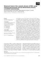
Four types of nanopore array distributions are discussed
here, as shown in Fig. 1. The pore sides of the nanonets
have numbers of dangling bonds. Thus, Si–O–Si, Si–OH,
as well as Si–H are selected as passivation bonds. Hydro-
gen atoms are usually used for passivation in constructing
models of nanoscale. However, it is known that Si–H bond
is of poor stabilization in the air. It will be replaced by
Si–O bond, which is a stable state on the silicon surface.
Si–O passivation is also easy to achieve by exposing the
sample in the air [14, 15], electrochemical oxidation [16],
or thermal oxidation [17] and has already been introduced
into the microelectronics devices. It has also been widely
studied in order to improve the luminescence property of
porous silicon [18]. For the 100 nanonets, most of the
L. Lin Á D. Li Á J. Feng (&)
Department of Materials Science and Engineering, Key Lab of
Advanced Materials, Tsinghua University, Beijing 100084,
China
e-mail:
123
Nanoscale Res Lett (2009) 4:409–413
DOI 10.1007/s11671-009-9259-0
silicon atoms on the pore walls have two dangling bonds.
We use oxygen-bridge to link neighboring silicon atoms in
sides and hydrogen atoms to passivate silicon atoms in
corners (Fig. 1a, b). For the 110 models, each silicon atom
on the pore walls has only one dangling bond. Therefore,
hydroxyl is used for passivation and the Si atoms in the
corners are also passivated by H in order to reduce the
internal stress (Fig. 1c, d). The special points in the reci-
procal space of the nanonets and the paths in our
calculation are shown in Fig. 1e. The coordinate axes in the
reciprocal space are established corresponding to the axes
of the real space shown in Fig. 1a–d.
The calculations of energy band structure of the silicon
nanonets were based on the local density approximation
and density function theory (LDA–DFT). The generalized
gradient approximation (GGA), for the exchange and cor-
relation effects [19] with the ultrasoft pseudopotentials [20]
was selected for the calculations. These pseudopotentials
require a quite low energy cut-off and guarantee good
transferability and robustness. A geometry optimization of
the silicon nanonets was carried out first with the atomic
positions and the crystal cell parameters relaxed by total
energy minimization. For the calculations of electronic
characteristic, the cut-off energy of 340 eV was assumed in
the plane-wave basis set, the SCF convergence tolerance of
the electronic energy per atom was 1 9 10
-6
eV and the
k-point separation was 0.4 nm
-1
.
Results and Discussion
After the geometry optimization of the silicon nanonets,
the atomic positions and the cell parameters become rea-
sonable. The bond lengths are similar to the results
reported in the study of siloxenic clusters [21]. As the
length of Si–O bond is much smaller than the Si–Si bond,
the distance between the silicon atoms which are linked by
the same oxygen atom becomes much smaller in the Si–O–
Si passivated nanonets. Hence, the presence of the oxygen
atoms on the nanowalls of the Si–O–Si passivated nanonets
produces a local diminution of the second-neighbor sepa-
ration for silicon lattice, and consequently a structural
contraction. For the –OH-passivated nanonet models, the
Si–Si bond length increases in the case that both of the
silicon atoms are linked with –OH, and decreases in the
case that one silicon atom is linked with hydroxyl while the
other with hydrogen. This is due to the different interac-
tions between the passivation atoms.
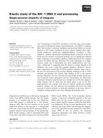
Figure 2 shows the band structures of Si and some
nanonets constructed with 4 9 4 9 1 supercell. Si exhibits
a typical indirect band gap. However, when the nanopore
arrays are introduced in the silicon supercell, both the
conduction band and the valence band are significantly
changed. The direct band gap structure appears in the
nanonets with special parameters.
In Fig. 2a, it is shown that the conduction band mini-
mum (CBM) of bulk Si moves to 1/3 GZ or X due to the
folding effect, which is in accordance with the theoretical
analysis. In the 100X nanonets, the notable changes of the
valence band occur at X. For the bulk Si, a valley exists at
point X, which is much lower than G. With the porosity
increases, the value of X increases and the valley disap-
pears when the porosity reaches 29%. The G–X are 0.26,
0.08, 0.06, and 0.04 eV for bulk Si, 100X4B4W4P16O,
100X3B4W2P29O and 100X4B6W2P45O, respectively.
However, G is always the valence band maximum (VBM)
in all the 100X nanonets we concerned, which is the same
with the location of VBM in bulk Si. In the conduction
band, the changes of X are most important. With the
porosity increases, the X–G changes from negative to
positive and the CBM moves from X to G, leading to an
indirect to direct band gap transition. All the 100X nano-
nets with porosities higher than 29% exhibit direct band
gap structure in our calculation (Fig. 2c, d). For the 100D
nanonets, it should be noted that the coordinate axes have
been rotated a degree of 45° compared with the 100X
nanonets. Thereby, the paths of ZAMGZRXG shown in the
band structure of 100D nanonets correspond to ZRXG-
ZAMG in the 100X nanonets. The location of CBM is fixed
at M and the change of the M–G in the valence band is the
key factor of the band gap transition. Our results show that
the values of M–G are negative for 100D3B4W2P25O and
Fig. 1 Schematic view of a 100X4B5W3P29O, b 100D5B5W2P29O,
c 110D4B6W2P20OH. d 110X4B6W2P20OH, and e special points in
the reciprocal space of nanonets. For (a)–(d), 100 or 110 represents the
orientations of the pore sides, Xi or Di depends on the shapes and the
sizes of the primitive cell of the silicon nanonets, Bj indicates the bore
diameters of the nanopore, Wk is the minimal widths of the nanowall,
Pn means the porosities of the silicon nanonets. OH means the
nanowalls are OH-passivated, while O indicates the nanowalls are
passivated by Si–O–Si. The crystal orientations of the primitive cells
of the 100D and 110X nanonets have a 45° rotation compared with the
other two models: the x and y-axis of 100X and 110D are [100], while
[110] for 110X and 110D
410 Nanoscale Res Lett (2009) 4:409–413
123
100D4B4W2P33O (Fig. 2e). However, when the porosity
reaches 37%, the G–M becomes positive and the VBM
moves from G to M and result in a direct band gap. Both
the Si–O–Si passivated 100X and 100D nanonets exhibit
the band gap transitions when the porosities are increased.
However, the location of the VBM and CBM are different
for these two models when direct band gap is obtained.
Both the VBM and CBM locate at G for the 100X nano-
nets, while M for the 100D nanonets. This indicates that the
distribution of the nanopore arrays is another key factor of
the band gap structure of nanonets.
The 110X nanonets have the same macro appearance
compared with the 100X nanonets, only with the difference
of the crystal orientation of Si substrate. It should also be
noted that a 45° rotation exists between the coordinate axes
of the 110X nanonets and the 100X nanonets, which lead to
the difference of the special points shown in the band
structure. The motion of CBM appears in the GZ path.
When the porosity is lower than 30%, the CBM stays at
1/6 GZ or 1/3 GZ (Fig. 2f). However, when the porosity
increases to 39%, the CBM move from 1/6 GZ or 1/3 GZ
to G (Fig. 2g). As the VBM always stays at X, the 110X
nanonets exhibit indirect band gap in various porosities we
study. The 110D nanonets can be treated as the 100X
nanonets with the pore side orientation rotates a degree of
45°. Similar to the 110X nanonets, the 110D nanonets with
different porosities in our study present indirect band gap
with the CBM at point X and the VBM at point M
(Fig. 2h). Both the –OH-passivated 110X and 110D nan-
onets have indirect band gap in different porosities, which
is rather different from the results of 100X and 100D
Si–O–Si passivated nanonets.
The pore wall width is the key factor in deciding the
band gap of the nanonets. With the decreases of the pore
wall width, the band gap increases due to the quantum
confinement effect caused by the nanoscale of the pore
walls. It should be noticed that the underestimation of the
band gap induced by the approximation in the electron
exchange-correlation energy in LDA–DFT method exists
in this study without any correction.
It is shown that nanonets with the nanopore array dis-
tributions of 100X and 100D exhibit direct band gap
characteristic when the porosity exceeds a special value.
However, the passivation bonds can also lead to the
changes of the band gap structure. In order to confirm our
arguments, the band gap structure of 100D nanonets with
different passivation conditions is studied here. The CBM
of 100D5B5W2P37H, all the dangling bonds on the
nanowalls of which are passivated by –H, stays at point G.
However, the XG path in the valence band is almost hor-
izontal, which indicates that the electrons on the
corresponding state act as a two-dimensional electron gas
in the real space (Fig. 3a). When the passivation bonds are
taken place by Si–O–Si, both the VBM and the CBM move
to M and result in a direct band gap (Fig. 3b). The value of
the band gap is also reduced due to the Si–O–Si passivation
Fig. 2 Energy band gap structure of Bulk silicon and nanonets with the
same cell size: 4 9 4 9 1 supercell. a Bulk Si (VBM: G, CBM: 1/3GZ,
Eg: 0.71 eV), b 100XB4W4P16O (VBM: G, CBM: X, Eg: 0.74 eV), c
100X4B5W3P29O (VBM: G, CBM: G, Eg: 0.49 eV), d 100X4B6
W2P45O (VBM: G, CBM: G, Eg: 0.32 eV), e 100D4B4W2P33O
(VBM: G, CBM: M, Eg: 0.90 eV), f 110X4B4W4P14OH (VBM: X
CBM: 1/6 GZ or 1/3 GZ Eg: 0.94 eV), g 110X4B6W2P39OH (VBM:
X, CBM: G, Eg: 1.07 eV), h 110D4B6W2P20OH (VBM: M, CBM: X,
Eg: 0.90 eV)
Nanoscale Res Lett (2009) 4:409–413 411
123
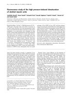
bonds. For further study of the effect of the different pas-
sivation bonds, the band structures of 110D nanonets with
the same nanopore structure but passivated by –H, –OH,
and Si–O–Si, respectively, were calculated here. As shown
in Fig. 4, 110D3B4W2P13H has an indirect band gap with
the VBM at M and CBM at X, which is almost the same
with 110D3B4W2P13OH. However, when the passivation
bonds are taken place by Si–O–Si, both the CBM and VBM
move to point G and a direct band gap structure is obtained.
This indicates that Si–O–Si bond is an effective passivation
bond which has greater influence on the band edge of
nanonets, compared with the H and OH-passivated nano-
nets. It is due to the contribution of the electrons on the O-
2p orbits in the Si–O–Si bond. The density of states (DOS)
near the band edge of nanonets contributed by the oxygen
atoms in Si–O–Si is larger than that of the hydrogen atoms
in Si–H and the oxygen atoms in Si–OH. It is noted that the
change of the band gap structure is not as obvious as that of
the 110D nanonets shown in Fig. 3. This is because the
number of the Si–O–Si bonds in the 110D3B4W2P13O is
limited. In addition, the band gap is found to be in con-
junction with the passivation bonds. The band gaps of
110D3B4W2P13H and 110D3B4W2P13OH are almost the
same, 0.96 and 0.98 eV, respectively. However, it
decreases to 0.86 eV for 110D3B4W2P13O, which may
lead to the red shift in the photoluminescence spectrum.
Conclusions
In summary, the structure design of oxygen-passivated
silicon nanonets could result in indirect–direct band gap
transitions of silicon. The Si–O–Si passivated 100X and
100D nanonets exhibit direct band gap characteristic when
the porosities exceed 29 and 37%, respectively. The –OH-
passivated 110D and 110X nanonets with different poros-
ities we concerned in this study have indirect band gap. Si–
O–Si bond has more effective influence on the band edge
region of the nanonets than –H or –OH bonds and is
expected to change the band gap structure of silicon nan-
onets. With the rapid development of the materials nano
fabrication, it is expected that this electronic characteristic
of the nanonets could be validated in experiments.
Acknowledgments This work was supported by National Natural
Science Foundation of China (Grant No. 50571050), the National
Basic Research Program of China (973 program, Grant No.
2007CB936601) and Tsinghua National Laboratory for Information
Science and Technology of China.
Fig. 3 Band gap structure of a
100D5B5W2P37H (VBM: X or
G, CBM: G, Eg: 1.28 eV), b
100D5B5W2P37O (VBM: M,
CBM: M, Eg: 0.59 eV)
Fig. 4 Band gap structure of silicon nanonets with the same parameters but different passivation conditions a 110D3B4W2P13H (VBM: M or
G, CBM: X, Eg: 0.96 eV), b 110D3B4W2P13OH (VBM: M, CBM: X, Eg: 0.98 eV), c 110D3B4W2P13O (VBM: G, CBM: G, Eg: 0.86 eV)
412 Nanoscale Res Lett (2009) 4:409–413
123
References
1. L.T. Canham, Appl. Phys. Lett. 57, 1046 (1990). doi:10.1063/
1.103561
2. L.T. Canham, W.Y. Leong, M.I.J. Beale, T.I. Cox, L. Taylor,
Appl. Phys. Lett. 61, 2563 (1992). doi:10.1063/1.108127
3. A. Halimaoui, C. Oules, G. Bomchll, Appl. Phys. Lett. 59, 304
(1991). doi:10.1063/1.105578
4. P. Mutti, G. Ghislotti, S. Bertoni, L. Bonoldi, Appl. Phys. Lett.
66, 851 (1995). doi:10.1063/1.113408
5. N.A. Hill, K.B. Whaley, Phys. Rev. Lett. 75, 1130 (1995). doi:
10.1103/PhysRevLett.75.1130
6. T.K. Sham, S.J. Nafter, P S.G. Kim, R. Sammynaiken, Y.H.
Tang, Phys. Rev. B 70, 45313 (2004). doi:10.1103/PhysRevB.
70.045313
7. L. Brus, J. Phys. Chem. 98, 3575 (1994). doi:10.1021/j100065a
007
8. B.T. Sullivan, D.J. Lockwood, H.J. Labbe
´
, Z H. Lu, Appl. Phys.
Lett. 69, 3149 (1996). doi:10.1063/1.116811
9. Z.H. Lu, D.J. Lockwood, J M. Baribeau, Nature 378, 258 (1995).
doi:10.1038/378258a0
10. L. Diehl, S. Mentese, E. Mu
¨
ller, D. Gru
¨
tzmacher, H. Sigg, Appl.
Phys. Lett. 81, 4700 (2002). doi:10.1063/1.1528729
11. H.S. Han, S.Y. Seo, J.H. Shin, J. Appl. Phys. 88, 2160 (2000).
doi:10.1063/1.1304838
12. J.H. Shin, S.Y. Seo, Appl. Phys. Lett. 76, 1999 (2000).
doi:10.1063/1.126234
13. H. Rong, A. Liu, R. Jones, O. Cohen, Nature 433, 292 (2005).
doi:10.1038/nature03273
14. Y.H. Ogata, T. Tsuboi, T. Sakka, S. Naito, J. Porous Mater. 7,63
(2000). doi:10.1023/A:1009694608199
15. G. Mattei, V. Valentini, V.A. Yakovlev, Surf. Sci. 2002(502), 58
(2002). doi:10.1016/S0039-6028(01)01898-2
16. R. Boukherroub, D.D.M. Wayner, D.J. Lockwood, Appl. Phys.
Lett. 81, 601 (2002). doi:10.1063/1.1492306
17. J. Salonen, V.P. Lehot, E. Laine, Appl. Phys. Lett. 70, 637
(1997). doi:10.1063/1.118294
18. B. Gelloz, A. Kojima, N. Koshida, Appl. Phys. Lett. 87, 031107
(2005). doi:10.1063/1.2001136
19. J.P. Perdew, J.A. Chevary, S.H. Vosko, K.A. Jackson, Phys. Rev.
B 46, 6671 (1992). doi:10.1103/PhysRevB.46.6671
20. D. Vanderbilt, Phys. Rev. B
41, 7892 (1990). doi:10.1103/
PhysRevB.41.7892
21. M.R. Pederson, W.E. Pickett, Phys. Rev. B 48, 17400 (1993)
Nanoscale Res Lett (2009) 4:409–413 413
123