báo cáo chuyên đề tiếng anh chuyên ngành
Bạn đang xem bản rút gọn của tài liệu. Xem và tải ngay bản đầy đủ của tài liệu tại đây (6.85 MB, 17 trang )
RUONG DAI HQC DIEN LUC
£
_
KHOA DIEU KHIEN & TU DONG HOA
ĐúI HỌC ĐIỆT LỰC
ELECTRIC POWER UNIYERSITY
BAO CAO CHUYEN DE
NGÀNH: Công nghệ kỹ thuật điều khiến và tự động hóa
CHUYÊN NGÀNH: Tự động hóa và điều khiển thiết bị cơng nghiệp
HỌC PHẢN: Tiếng Anh chuyên ngành
Giảng viên hướng dẫn: Nguyễn Ngọc Khốt
Nhóm sinh viên/ sinh viên thực hiện — Mã sinh viên:
Nhóm 3 : Nguyễn Khánh Hùng Khơi - 19810430152
Trần Lâm Hải Long - 19810430211
Lê Hoàng Minh - 19810430138
Trần Anh Thắng - 19810430273
Lop : DI4ATDH&DKTBCN3
HA NOL, 2/2022
Dé tai nhom 3:
Tiéng Anh Chuyén Nganh
Chuong 1: Introduction to power sources (DC and AC power)
1.1. Definition
1.2. How to use power sources in an electrical circuit?
1.3. How to produce power sources?
1.4. How internal resistance of power sources affects operation of an electrical circuit?
1.5. Ohm’s law of an electrical circuit regarding power sources
1.6. Applications of power sources
Chuong 2: Synchronous AC motors
2.1. Concept
2.2. Classification
2.3. Structure
2.4. Working principle
2.5. Speed control methods for the synchronous AC motors
2.6. Applications
Chwong 3: Introduction to PLC Mitsubishi
3.1. What is PLC?
3.2. What are differences between PLC and traditional relay circuits?
3.3. Select and present briefly a PLC of Mitsubishi
Nguyễn Khánh Hùng Khôi 19810430152
Tiéng Anh Chuyén Nganh
LOI CAM ON
Trong thời gian làm báo cáo chuyên dé, em đã nhận được nhiéu sự giúp đỡ,
đóng góp ý kiến và chỉ bảo nhiệt tình của thầy cô và bạn bè. Em xin gửi lời cảm ơn
chân thành đến thầy Nguyễn Ngọc Khoát, giảng vên người đã tận tình hướng dẫn,
chỉ bảo em trong suốt quá trình làm chuyên dé điều khiến số. Em
cũng xin chân
thành cảm ơn thây cô giáo trường Đại học Điện Lực nói chung, các thây cơ bộ mơn
điện tử cơng suất nói riêng đã hướng dẫn cho em kiến thức về cách trình bày và nội
dung đồ án, giúp em có được cơ sở lý thuyêt và tạo điều kiện gúp đỡ em trong quá
trình làm báo cáo chuyên đề. Tuy vậy, với kinh nghiệm và kiến thức cịn thiếu sót
nên bản báo cáo chuyên dé của em còn chưa được hoàn thiện lắm, em mong được sử
chỉ dẫn chân thành của các thây cô.
Cuối cùng, em xin chân thành cảm ơn thầy cô và bạn bè đã luôn tạo đều kiện,
quan tâm, giúp đỡ em trong suốt quá trình học tập và hồn thành báo cáo.
Nguyễn Khánh Hùng Khơi 19810430152
Tiéng Anh Chuyén Nganh
Chuong 1: Introduction to power sources (DC and AC power)
1.1. Definition
Alternating current power is the standard electricity that comes out of power
outlets and is defined as a flow of charge that exhibits a periodic change in direction.
AC's current flow changes between positive and negative because of electronselectrical currents come from the flow of these electrons, which can move in either a
positive (upward) or negative (downward) direction. This is known as the sinusoidal
AC wave, and this wave is caused when alternators at power plants create AC power.
Alternators create AC power by spinning a wire loop inside a magnetic field. Waves of
alternating current are made when the wire moves into areas of different magnetic
polarity—for example, the current changes direction when the wire spins from one of
the magnetic field's poles to the other. This wave-like motion means that AC power
can travel farther than DC power, a huge advantage when it comes to delivering power
to consumers via power outlets.
Direct current (DC) power, as you may guess from the name, is a linear
electrical current—it moves in a straight line.
Direct current can come from multiple sources, including batteries, solar cells, fuel
cells, and some modified alternators. DC power can also be "made" from AC power by
using a rectifier that converts AC to DC. DC power is far more consistent in terms of
voltage delivery, meaning that most electronics rely on it and use DC power sources
such as batteries. Electronic devices can also convert AC power from outlets to DC
power by using a rectifier, often built into a device's power supply. A transformer will
also be used to raise or lower the voltage to a level appropriate for the device in
question.
1.2. How to use power sources in an electrical circuit?
Power sources do two important things:
+) They supply energy to the circuit in the form of an electric potential difference.
+) They provide a source and sink for electrons in a circuit.
As a simple analogy, you can think of a power source as the heart of a circuit;
just as our heart circulates blood to enable our bodies to function, electric power
sources pump or circulate electrons, enabling electric circuits to function.
You can think of a power source as a ‘pump’ that keeps electrons flowing in a
circuit. Without a power source, a circuit will quickly lose energy due to the electrical
resistance of its components.
Power sources are known as active components because they supply energy to
the electric circuit.
Power sources supply electric power by pushing and pulling the electrons in a
circuit. Without a power source, circuits quickly stop working due to energy losses.
Think about the battery in your phone or tablet. When the battery runs out of charge, it
stops functioning as a power source and your device quickly shuts down. Power
sources are really important because every circuit and component relies on them in
order to function. We start our discussion on circuits with power sources because they
are the beating heart of every circuit.
Nguyễn Khánh Hùng Khôi 19810430152
Tiéng Anh Chuyén Nganh
1.3. How to produce power sources?
The three major categories of energy for electricity generation are fossil fuels
(coal, natural gas, and petroleum), nuclear energy, and renewable energy sources.
Most electricity 1s generated with steam turbines using fossil fuels, nuclear, biomass,
geothermal, and solar thermal energy. Other major electricity generation technologies
include gas turbines, hydro turbines, wind turbines, and solar photovoltaics.
1.4. How
circuit?
internal resistance of power sources affects operation of an electrical
In the case of circuits, the equivalent of ‘friction’ 1s something called electric
resistance. Every electric component has some amount of electric resistance. Even
conductors like wires have some resistance to the movement of electrons. That’s
because conductors don’t conduct electricity perfectly, and they lose some energy as
heat as a result. The energy loss quickly causes all the electrons in the circuit to stop
moving when disconnected from the power source, even if the circuit remains closed.
In AC circuits, resistance is called impedance. That’s because the total
‘resistance’ to current flow in an AC circuit doesn’t just come from electric resistance.
Capacitance and inductance also contribute to the overall opposition to current flow in
an AC circuit. The total opposition to current flow, caused by resistance, capacitance
and inductance is called impedance.
1.5. Ohm’s law of an electrical circuit regarding power sources
The current through a resistor is in direct proportion to the voltage across the
resistor's terminals. This relationship is represented by Ohm's law:
Where I is the current through the conductor in units of amperes, V is the
potential difference measured
across the conductor
in units of volts, and R is the
resistance of the conductor in units of ohms (symbol: Q).
1.6. Applications of power sources
For DC
e DC current limited by a resistor causes light-emitting diodes (LEDs) to produce
light.
e
e
Mechanical and electronic switches can deliver large amounts of DC control
current to motors, solenoids, and resistive heaters.
DC currents and voltages establish the electrical conditions that allow
transistors to amplify AC signals
For AC
e Cell phones.
Flashlights\
The Lilypad-based D&D Dice Gauntlet.
Flat-screen TVs (AC goes into the TV, which is converted to DC)
Hybrid and electric vehicles.
Nguyễn Khánh Hùng Khôi 19810430152
Tiéng Anh Chuyén Nganh
Chuong 2: Synchronous AC motors
2.1. Concept
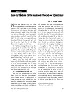
A synchronous electric motor is an AC electric motor in which, at steady state,
the rotation of the shaft 1s synchronized with the frequency of the supply current; the
rotation period is exactly equal to an integral number of AC cycles. Synchronous
motors contain multiphase AC electromagnets on the stator of the motor that create a
magnetic field which rotates in time with the oscillations of the line current. The rotor
with permanent magnets or electromagnets turns in step with the stator field at the
same rate and as a result, provides the second synchronized rotating magnet field of
any AC motor. A synchronous motor is termed doubly fed if it is supplied with
independently excited multiphase AC electromagnets on both the rotor and stator.
What are Synchronous
Motors?
‹5
St, hy,
3
DC
Supply
Synchronous
Motor
_
@® Electrical 4 U
Qed
The synchronous motor and the induction motor are the most widely used types
of AC motors. The difference between the two types is that the synchronous motor
rotates at a rate locked to the line frequency since it does not rely on current induction
to produce the rotor's magnetic field. By contrast, the induction motor requires slip: the
rotor must rotate slightly slower than the AC alternations in order to induce current in
the rotor winding. Small synchronous motors are used in timing applications such as in
synchronous clocks, timers in appliances, tape recorders and precision
servomechanisms in which the motor must operate at a precise speed; speed accuracy
is that of the power line frequency, which is carefully controlled in large
interconnected grid systems.
Synchronous motors are available in self-excited sub-fractional horsepower
sizes to high power industrial sizes. In the fractional horsepower range, most
synchronous motors are used where precise constant speed is required. These
Nguyễn Khánh Hùng Khôi 19810430152
Tiéng Anh Chuyén Nganh
machines are commonly used in analog electric clocks, timers and other devices where
correct time is required. In higher power industrial sizes, the synchronous motor
provides two important functions. First, it is a highly efficient means of converting AC
energy to work. Second, it can operate at leading or unity power factor and thereby
provide power-factor correction.
2.2. Classification
Synchronous motors are classified according to their speed. They are either
high-speed or low-speed machines. Those operating over 500 RPM are designated
high-speed motors.
Beside speed, synchronous motors can be classified by type. There are different
types of synchronous motors based on the way they are excited
e
e
Non Excited Synchronous Motors
Current Excited Synchronous Motors
Non Excited Synchronous Motor
The rotor is made up of steel. The external magnetic field magnetizes the rotor,
and it rotates in synchronism with it. The rotor is generally made of high retentivity
steel such as cobalt steel.
Non-excited motors are available in three designs:
+) Hysteresis Motor
Hysteresis motors are single phase motors in which the rotor is made up of
ferromagnetic material. The rotors are cylindrical in shape and have high hysteresis
loss property. They are generally made up of chrome, cobalt steel or alnico. The stator
is fed by single phase AC supply. The stator has two windings:
1. main windings and
2.
auxiliary windings.
The combination of the two produces a revolving magnetic field from a single
phase supply. They are self-starting and do not need additional windings. When single
phase AC supply is given, a rotating magnetic field is produced. This rotating
magnetic field induces eddy currents in the rotor. The rotor starts to move initially
with a slip. When the rotor reaches synchronous speed, the stator pulls the rotor into
synchronism. So initially the motor starts as an induction motor and later runs as a
synchronous motor.
+) Reluctance Motor
The reluctance motor is based on the principle that an unrestrained piece of iron
will move to complete a magnetic flux path where the reluctance is minimum. The
stator has the main winding and the auxiliary windings just like the hysteresis motor.
These help to create a rotating magnetic field. The rotor of a reluctance motor 1s a
squirrel cage rotor with some teeth removed to provide the desired number of salient
Nguyễn Khánh Hùng Khôi 19810430152
Tiéng Anh Chuyén Nganh
poles. The reluctance becomes minimum when the rotor is aligned with the magnetic
field of the stator.
When single phase AC supply is given, the motor starts as an induction motor.
The rotor tries to align itself with the magnetic field of the stator and experiences
reluctance torque. But due to inertia, it exceeds the position and again tries to align
itself during the next revolution. In this manner, it starts to rotate. Once it reaches 75%
of synchronous speed, the auxiliary windings are cut off. When the speed reaches
synchronous speed, the reluctance torque pulls it into synchronism. The motor remains
in synchronism due to synchronous reluctance torque.
+) Permanent Magnet Synchronous Motors
The rotor is made up of permanent magnets. They create a constant magnetic
flux. The rotor locks in synchronism when the speed is near synchronous speed. They
are not self-starting and need electronically controlled variable frequency stator drive.
Direct Current Excited Motor
Direct current excited synchronous motors need a DC supply to the rotor to
generate rotor magnetic field. A direct current excited motor has both stator windings
as well as rotor windings. They can either have cylindrical rotors or salient pole rotors.
They are not self-starting and need damper windings to start. Initially, they start as an
induction motor and later attains synchronous speed.
Nguyễn Khánh Hùng Khôi 19810430152
Tiéng Anh Chuyén Nganh
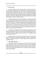
2.3. Structure
The construction of synchronous motor is similar to that of a synchronous
alternator. Most of the synchronous motors construction uses the stationary armature
and rotating field winding. This type of construction as an advantage than DC motor
type where the armature used 1s of rotating type
Nguyễn Khánh Hùng Khôi 19810430152
Tiéng Anh Chuyén Nganh
3 Phase supply
St,to,
DC
Supply
Synchronous Motor
2.4. Working principle
The principle of operation of a synchronous motor can be understood by
considering the stator windings to be connected to a three-phase alternating-current
supply. The effect of the stator current is to establish a magnetic field rotating at
120 f/p revolutions per minute for a frequency of fhertz and for p poles. A direct
current in a p-pole field winding on the rotor will also produce a magnetic field
rotating at rotor speed. If the rotor speed 1s made equal to that of the stator field and
there is no load torque, these two magnetic fields will tend to align with each other. As
mechanical load is applied, the rotor slips back a number of degrees with respect to the
rotating field of the stator, developing torque and continuing to be drawn around by
this rotating field. The angle between the fields increases as load torque 1s increased.
The maximum available torque is achieved when the angle by which the rotor field
lags the stator field is 90°. Application of more load torque will stall the motor.
Nguyễn Khánh Hùng Khôi 19810430152
10
Tiéng Anh Chuyén Nganh
TOPE
LIOF
One advantage of the synchronous motor is that the magnetic field of the
machine can be produced by the direct current in the field winding, so that the stator
windings need to provide only a power component of current in phase with the applied
stator voltage—.e., the motor can operate at unity power factor. This condition
minimizes the losses and heating in the stator windings.
The power factor of the stator electrical input can be directly controlled by
adjustment of the field current. If the field current is increased beyond
the value required to provide the magnetic field, the stator current changes to include a
component to compensate for this overmagnetization. The result will be a total stator
current that leads the stator voltage in phase, thus providing to the power system
reactive volt-amperes needed to magnetize other apparatuses connected to the system
such as transformers and induction motors. Operation of a large synchronous motor at
such a leading power factor may be an effective way of improving the overall power
factor of the electrical loads in a manufacturing plant to avoid additional electric
supply rates that may otherwise be charged for low power-factor loads.
2.5. Speed control methods for the synchronous AC motors
Synchronous motors are constant speed motors. They run at the synchronous
speed of the supply. They are generally used for constant speed operation under no
load conditions such as to improve the power factor. Synchronous motors have fewer
losses than induction motors at a given rating.
The speed of a synchronous motor is given by
N
_ 120ƒ
Pp
As you can see, the synchronous speed depends on the frequency of the supply
and the number of poles of the rotor. Changing the number of poles is not easy, so we
Nguyễn Khánh Hùng Khôi 19810430152
11
Tiéng Anh Chuyén Nganh
do not use that method. However, with the invention of solid-state devices, the
frequency of the current fed to the synchronous motor can be varied. We can control
the speed of the synchronous motor by changing the frequency of the supply to the
motor.
We can use a combination of rectifiers and inverters to control the speed of
synchronous motors. They can be used in two ways:
e
e
Inverter Fed Open Loop Synchronous Motor Drive: In this method, the
synchronous motor is supplied by variable frequency inverter in an open loop.
By open loop, we mean that there is no feedback given to the supply. The
inverter has no information about the current position of the rotor. This method
is preferable when highly accurate speed control is not required. Supply from
the mains is fed into the rectifier inverter set where desired frequency can be
attained. Depending on the frequency, the synchronous speed of the motor can
be varied.
Self Synchronous (Closed — Loop) Operation: We use self-synchronous
(closed-loop) operation when highly accurate speed control is required. In this
method, the inverter output frequency is determined by the speed of the rotor.
The speed of the rotor is fed back to the differentiator. The difference between
the preset speed and the actual
inverter changes the frequency
accurate control over the motor
example, if speed gets reduced
speed is fed to the rectifier. Accordingly, the
and adjusts the speed of the motor. We get more
speed with the closed loop operation. For
(due to increase in load), the stator supply
frequency gets reduced so that the rotor stays in synchronism with the stator
magnetic field. No spontaneous oscillation or hunting occurs in this method.
2.6. Applications
Synchronous motors can be used toraise overall the power factor of the
installation. When a synchronous motor is run without load with over-excitation for
improving the power factor of an installation, it is called as the synchronous capacitor
or synchronous condenser.
Synchronous motors are also used to regulate the voltage at the end of
transmission lines.
Because of the higher efficiency possible with synchronous motors, they can be
used for loads where constant speed is required.
Synchronous motors can be built for speeds as low as 120 RPM. They are well-
suited for direct connection to reciprocating compressors.
Nguyễn Khánh Hùng Khôi 19810430152
12
Tiéng Anh Chuyén Nganh
Chuong 3: Introduction to PLC Mitsubishi
3.1. What is PLC?
3.1.1. Definition
Programmable Logic Controller, PLC, or Programmable Controller is a digital
computer used for automation of industrial processes, such as control of machinery on
factory assembly lines. Unlike general-purpose computers, the PLC is designed for
multiple inputs and outputs arrangements, extended temperature ranges, immunity to
electrical noise, and resistance to vibration and impact. Programs to control machine
operation are typically stored in battery-backed or non-volatile memory. A PLC is an
example of a real time system since output results must be produced in response to
input conditions within a bounded time, otherwise unintended operation will result.
3.1.2. Features
The PLC engineering environment has undergone outstanding innovation and
growth. We are now entering the era of MELSEC Engineering Software! MELSEC's
many different software products provide solutions for TCO reduction in an
engineering environment, using methods such as improving design efficiency,
shortening debugging time, reducing downtime, and data holding.
e
e
iQ Works: This integrated software suite includes various programming
software for PLC, motion control, and GOT.
GX Works3: The next-generation engineering software contributes to
development cost reduction with its intuitive programming environments.
GX Works2: This sequence programming software uses the program assets
cultivated by GX Developer to pursue a more comfortable level of operability.
PX Developer: This software enables easy loop control programming with
e
MX Component: This Active X controller library enables easy communication
e
e
e
e
e
simple drag & drop operations.
processing from the PC and tablet to PLC, without the need for communication
protocol awareness.
MX Sheet: Software which uses Excel to easily monitor, log, collect alarm
information and change configurations for the PLC.
iQ AppPortal: MELSOFT iQ AppPortal 1s software used to manage assets
integrated for each purpose, such as project files of MELSOFT products or
design drawings/documents.
FieldDeviceConfigurator: A Field Device managing/setting software which is
MITSUBISHI ELECTRIC products and it is corresponding to FDT/DTM open
specification. And it can be used as a FDT frame application to set the
parameters of Field Device, or to maintain/adjust the device.
Nguyễn Khánh Hùng Khôi 19810430152
Tiéng Anh Chuyén Nganh
e
Other engineering softwares: Lineup of various software to support the
MELSEC Series engineering environment.
e
Peripheral equipment support tools: Lineup of various free tools that further
simplify development of the MELSEC Series.
e-Manual: e-Manual for the Mitsubishi FA product users for quick search of
e
necessary information.
3.1.3. Applications
Automotive: Improve productivity and realize flexibility in different automotive
assembly lines with high-accuracy motion control, including linear/circular
interpolation and electric cam profile.
Ta
Automated warehouse: Realize advanced logistics coordination and eliminate errors
in repetitive processes. Servo-based high-speed material handling and highly accurate
positioning 1m
`
os
"
:
sử Tm=c
AI
Í
Xã
and reduce energy consumption.
-
Food and beverage, CPG: Realize improvements in various packaging applications
such as high-speed filling, which requires a highly accurate, continuous feed rate and
recision.
Semiconductor: Reduce maintenance costs using the high-durability MELSEC
Having the compact, robust design desired for semiconductor manufacturing,
MELSEC products solve the small footprint, high-performance requirements.
Nguyễn Khánh Hùng Khôi 19810430152
Series.
14
Tiéng Anh Chuyén Nganh
-
` `
Pick-and-place: Achieve highly precise, fast and accurate placement of components
in various sizes and shapes such as that required by SMT pick-and-place equipment,
further improving
productivity.
Flat panel display (FPD): Improve the large data bandwidth and high-performance
requirements common in FPD manufacturing processes using MELSEC's integrated
control platform. The integrated controller and network solution offer increased
flexibility
>
and enhanced
performance.
Renewable energy Easily integrate renewable energy plant management utilizing
plant-wide data acquisition and extensive real-time control, thereby reducing overall
investment and maintenance costs.
3.1.4. What 1s timing diagram
Timer accumulative timers of four types: low-speed timer, high-speed timer, lowspeed integrator, and high-speed integrator.
The PLC takes a certain amount of time to react to changes. The total response time of
the PLC 1s a fact that has to be considered while selecting a PLC for some application
where speed is a concern.
Hence, Input Response Time + Program Execution Time + Output Response
Time = Total Response Time. Having understood the concept behind the response
Nguyễn Khánh Hùng Khôi 19810430152
15
Tiéng Anh Chuyén Nganh
time, let us see what happens in a typical PLC Applications. The PLC can only see an
input turn ON/OFF when its looking. In other words, it only looks at its inputs during
the check input status part of the scan.
3.1.5. Advantages and disadvantages of PLCs
Advantages:
e
Small physical size & shorter project time.
Cost effective for controlling complex system.
Reliability.
Less and simple wiring.
Faster response.
Remote control capability.
More flexibility.
Ease of maintenance / troubleshooting.
Disadvantages:
e Fixed circuit operation.
e PLCs manufacturers offer only closed loop architecture.
e
e
PLCs are propitiatory, which means software and parts one manufacturer can’t
be easily used in combination with part of another manufacturer.
Number of optional modules must be added to maximize flexibility and
performance.
3.2. What are differences between PLC and traditional relay circuits?
Speed of
response
10 capacity
Logic
development
Redundancy
Architecture
PROGRAMMABLE LOGIC
CONTROLLERS (PLC)
DISTRIBUTED CONTROL
SYSTEMS (DCS)
PLCs are can respond to a
DCS are slower than PLCs.
second.
30ms.
A DCS can handle thousands of
IOs. It can handle hundreds or
change within one-tenth of a
A PLC 1s capable of handling
few hundred IOs. When it
comes to analog IOs, it can
handle tens of them.
PLC can programmed be
programmed based on our
application.
PLCs can be made redundant
with additional hardwares
which makes them expensive
than DCS.
PLCs have a simple and
flexible architecture. A PLC
system consists of controllers,
IO modules, HMIs and an
Nguyễn Khánh Hùng Khôi 19810430152
Typical respond time of DCS is
even thousands of analogs IOs
and PID functions
DCS comes with built-in control
functions that need to be
configured based on the
application.
Redundancy is a default feature
of distributed control systems.
DCS systems are less flexible.
They come with controllers, IO
systems, database servers,
engineering and operating
16