Báo cáo hóa học: " Research Article Content-Adaptive Packetization and Streaming of Wavelet Video over IP Networks" pot
Bạn đang xem bản rút gọn của tài liệu. Xem và tải ngay bản đầy đủ của tài liệu tại đây (3.84 MB, 12 trang )
Hindawi Publishing Corporation
EURASIP Journal on Image and Video Processing
Volume 2007, Article ID 45201, 12 pages
doi:10.1155/2007/45201
Research Article
Content-Adaptive Packetization and Streaming of Wavelet
VideooverIPNetworks
Chien-Peng Ho and Chun-Jen Tsai
Department of Computer Science, National Chiao Tung University, Hsinchu 30010, Taiwan
Received 22 August 2006; Revised 2 December 2006; Accepted 5 January 2007
Recommended by B
´
eatrice Pesquet-Popescu
This paper presents a framework of content-adaptive packetization scheme for streaming of 3D wavelet-based video content over
lossy IP networks. The tradeoff between rate and distortion is controlled by jointly adapting scalable source coding rate and level
of forward error correction (FEC) protection. A content dependent packetization mechanism with data-interleaving and Reed-
Solomon protection for wavelet-based video codecs is proposed to provide unequal error protection. This paper also tries to
answer an important question for scalable video streaming systems: given extra bandwidth, should one increase the level of chan-
nel protection for the most important packets, or transmit more scalable source data? Experimental results show that the proposed
framework achieves good balance between quality of the received video and level of error protection under bandwidth-varying
lossy IP networks.
Copyright © 2007 C P. Ho and C J. Tsai. This is an open access article distributed under the Creative Commons Attribution
License, which permits unrestricted use, distribution, and reproduction in any medium, provided the orig inal work is properly
cited.
1. INTRODUCTION
There is a growing demand for video transmission over het-
erogeneous networks for communication and entertainment
applications. Scalable video coding (SVC) techniques are of-
ten proposed for such systems since, ideally, a video sequence
can be encoded once and adapted on the fly to different
frame rate, bitrate, and resolution for different applications.
Although scalable video is an interesting concept, it takes
complete end-to-end system design to show the advantage
of SVC over single-layer coding techniques. With single-layer
coding, techniques like bitstream switching and simulcasting
can be used to achieve video adaptations. However, it is eas-
ier to a chieve good rate versus source-and-channel distortion
tradeoff with scalable coding techniques.
The mainstream video compression techniques are based
on hybrid motion-compensated transform coding approach,
where the transform algorithms are typically either discrete
cosine transform (DCT) or 3D wavelet transform [1]. So
far, DCT-based SVC approaches have demonstrated better
coding efficiency than wavelet-based SVC techniques [2],
especially for low bitrate applications. However, a wavelet-
based SVC framework can provide fine-granularity bitrate
(i.e., SNR) scalability with less system complexity than that
of an FGS-based DCT framework. In addition, many ongo-
ing efforts show that wavelet-based SVC approaches still have
room for improvement [3]. Therefore, in this paper, wavelet-
based SVC is used as the core codec for the development of a
scalable video streaming framework.
The most challenging problem for scalable video stream-
ing over IP networks is about how to optimally adapt
source data rate and degree of packet loss protection to real-
time network conditions. Video packet packetization and
scheduling algorithms are mostly responsible for mitigating
the effects of bandwidth variation and packet losses in the
network. The packetization and scheduling algorithms are
mainly based on resource-versus-distortion optimization [4–
7], where resource can be available computation power, rate,
delay, and so forth. A general resource allocation treatment
for streaming systems is presented in [5]. Some researches
try to apply the rate-distortion optimization (RDO) prin-
ciple [8] of source coding theories to video streaming over
lossy networks [4]. For a streaming system, the distortion is
a result from both source coding and channel losses. A key is-
sue in an RDO-based streaming system is that the distortion
duetopacketlossesismuchmoredifficult to quantify than
the distortion due to lossy source coding.
Several frameworks for 3D wavelet based v ideo streaming
system have been proposed in the literature recently. Chu and
Xiong [9] introduced a combined packetized wavelet video
2 EURASIP Journal on Image and Video Processing
coding and FEC approach for v ideo streaming and multi-
cast. The packetized wavelet video coder marks the trunca-
tion points of the bit stream at the nearest packet boundaries
(instead of the end of each fra ctional bit plane). In the FEC-
based error protection scheme, it applies Reed-Solomon (RS)
coding to produce parity packets. And then the scheme
broadcasts all source packets to one multicast group and par-
ity packets to different multicast groups. Hence, for each
client, the optimal number of layers and error protection
to subscribe to can be determined by the packet loss ra-
tio and the available channel bandwidth. However, data in-
terleaving is not used in this work, which makes the sys-
tem less robust to burst errors. Dong and Zheng [10]pro-
posed a content-based retransmission framework for wavelet
video streaming. The compression module adopts dynam-
ical grouping and bounded coding scheme for improving
compression efficiency and removing unnecessary depen-
dency to each coefficient subband. In the transmission mod-
ule, a video packet includes one or more subbands, and a
content-based retransmission is used to provide robustness
against transmission errors. The content-based retransmis-
sion scheme is based on the importance of packet content
which is computed by the square sum of coefficients for each
wavelet subband. Later, Zhao et al. [11] incorporated an error
concealment scheme into this content-based retransmission
framework to increase its error resilience capability. Never-
theless, retransmission-based error control requires longer
jitter buffer and m ay consume too much extra bandwidth in
high error rate channels [12, 13].
Chou and Miao [4] developed a framework for RDO
streaming of packetized media. The RDO framework is flex-
ible to extend the optimizing packet transmission schedul-
ing to a wide range of receiver/sender/proxy driven stream-
ing systems [14]. However, the scheme maps (probability of)
packet losses into rate increment of redundant packet for-
ward transmission (ARQ can be avoided in this approach).
However, although redundant packet t ransmission makes
the RDO system simpler for analysis, it is not cost-effective
for practical systems. R-D performance can be greatly im-
proved if FEC is used instead. Zhu et al. [6]proposeda
congestion-distortion optimized scheme. Zhai et al. [7]pre-
sented an integrated joint source-channel coding frame-
work for video st reaming. Wang et al. [15]proposeda
cost-distortion optimization framework. Chang et al. also
proposed sender-based [16] and receiver-based [17]RDO
frameworks for 3D wavelet video streaming, which basically
follow the framework introduced by Chou and Miao. The
proposed system uses source rate-distortion profiles to opti-
mize for playout latency and bandwidth allocation among a
group of data packets in a way that minimizes distortion in
the reconstructed f rames.
There are many error control schemes for video stream-
ing, including forward error correction (FEC) [18–21], un-
equal error protection (UEP) [22–24], and automatic re-
transmission request (ARQ) [25]. Until recently, error con-
trol schemes for streaming systems are designed indepen-
dently to rate control schemes. Joint design of error and rate
control is important to a variable bandwidth lossy network.
For example, when the channel bandwidth increases during
runtime, should more bits be allocated to send extra (en-
hancement) source data, or to increase the level of protection
of crucial (also known as base layer) source data? Based on
the RDO principle, one should pick whichever approach that
reduces more distortion. However, this is not trivial since dis-
tortions from channel losses are nondeterministic. Another
issue is that not all source data bits carry equal amount of
information (i.e., entropy). Although some of the error con-
trol techniques try to put different degree of protection based
on the degree of importance of the content, unequal error
protection is done coarsely since the error control scheme is
based on either single-layer video coding model or coarse-
granularity layered scalable video coding mode.
In this paper, a content-adaptive packetization scheme
for wavelet-based streaming video is proposed. The mech-
anism is based on detail analysis of the mainstream wavelet-
based video codec [26]. Due to its fine-granularity SNR scal-
ability feature, the proposed packetization scheme can apply
various degrees of Reed-Solomon (RS) codes on interleaved
video subband data so that the streaming video is very robust
over IP networks. In addition, the paper proposes to map
the distortion caused by packet loss to distortion caused by
source data rate reduction due to extra FEC protection (for
error-free transmission). Since measuring operational video
distortion from packet loss is very difficult while measur-
ing source coding distortion is much simpler, the proposed
mechanism can be applied to practical systems. In summary,
the main features of the proposed system are highlighted as
follows.
(1) The streaming algorithm searches along the R-D curve
for an optimal operating point between the scalable
source coding rate and the FEC protection level.
(2) The FEC protection level is also influenced by run-
time packet loss rate feedback from the client. There-
fore,itisadaptivetoboththevideocontententropy
and the run-time packet loss rate.
(3) The rate-distortion tradeoff of the system takes into
account both distortion due to source data rate reduc-
tion and distortion due to packet losses (predicted by
FEC protection bits required for error-free transmis-
sion).
The rest of this paper is organized as follows. Section 2
presents a detail analysis on the wavelet compressed video
bit stream and its characteristics for content-adaptive pro-
tection. The detail of the proposed packetization scheme and
streaming framework is described in Section 3.Someexperi-
mental results of the proposed system are shown in Section 4.
Finally, some conclusions and discussions are given in Sec-
tion 5.
2. INVESTIGATION OF WAVELET VIDEO BIT
STREAMS WITH DATA LOSSES
For streaming applications, the quality of video is a
ffected by
packet losses. One of the most difficult problems for RDO
streaming is about how to measure the distortion caused by
C P. Ho and C J. Tsai 3
Input video
sequence
First temporal
level
Second temporal
level
P(H
t
, YUV)
P(LL
t
, YUV) P(LH
t
, YUV)
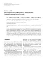
Figure 1: Wavelet video coding block diagr am.
Block depth
Block
height
Block width
P(H
t
, YUV)
Figure 2: Examples of coding block in wavelet video coding.
packet losses. The distortion depends heavily on the source
coding method. In this section, the wavelet video coding
schemes presented in [26, 27] are investigated in detail. In
particular, some experiments are conducted to exhibit the
impact of different wavelet subband data losses on the recon-
structed video quality.
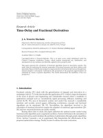
The block diagram of a wavelet-based video coding sys-
tem is shown in Figure 1. In a T + 2D wavelet coder, an
input video sequence is temporally decomposed first using
motion-compensated temporal filtering (MCTF) [1]. The
output of MCTF is then further decomposed by a 2D spa-
tial wavelet transform on a frame-by-frame basis. For exam-
ple, two-level temporal decomposition results in three tem-
poral subbands, namely, P(H
t
, YUV), P(LH
t
, YUV), and
P(LL
t
, YUV). When the group of pictures (GOPs) size is
eight, a typical set of transformed subband data produced
by the T + 2D wavelet coder has four P(H
t
, YUV)frames,
two P(LH
t
, YUV)frames,andtwoP(LL
t
, YUV)frames.
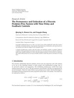
Each fr ame contains one luminance component (Y)and
two chrominance components (U and V). The coefficients
of different subbands are logically segmented into coding
blocks, based on the structure of Figure 2, and each cod-
ing block is independently coded by an entropy coder. For
instance, a coding block size in Figure 2 has block depth
2
4
6
8
10
12
14
16
×10
6
Distortion
02468101214
×10
4
Rate
P(H
t
, Y)- block 0
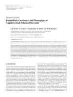
Figure 3: The R-D curve of coding block 0 of subband P(H
t
, Y)of
STEFAN.
2(i.e.,twoframes),blockheight36(=288/2
3
), and block
width 44 (
=352/2
3
). Common entropy coding techniques for
wavelet video are 3D embedded subband coding with opti-
mized truncation (3D-ESCOT) [27] and 3D set partitioning
in hierarchical trees (3D-SPIHT) [28]. The 3D-ESCOT algo-
rithm has higher compression efficiency and better scalabil-
ity than the 3D-SPIHT algorithm. Therefore, the proposed
scheme is based on 3D-ESCOT coding technique.
During the 3D-ESCOT entropy coding process, the en-
tropy coder (fractional bit plane coding and context-based
arithmetic coding) operates one coding block at a time, and
each coding block consists of N total bit planes, where N is
the number of bits in the most significant coefficients. Three
encoding operations of the context-based arithmetic cod-
ing (zero coding, sign coding, and magnitude refinement)
are used to characterize the significance of coefficients in a
bit plane. Following the 3D context modeling, fractional bit
plane coding ensures that the bit stream is a rranged with
fine granularity of SNR scalability for each coding block.
The fractional bit plane coding procedure consists of three
distinct passes which are the significant propagation pass,
the mag nitude refinement pass, and the normalization pass.
Since the first bit plane of a coding block can only be pro-
cessed with the normalization pass, a coding block contains
3N
− 2 coding passes. After entropy coding, candidate trun-
cation points of a coding block are associated with rate-
distortion slopes (R-D slopes). Any truncation points that
are not on the convex hull are eliminated, and the R-D slopes
are λ
0
, λ
1
, , λ
3N−2
,where|λ
0
| > |λ
1
| > ··· > |λ
3N−2
|.All
coding blocks have R-D curves similar to the example shown
in Figure 3, and the top coding passes contain the most im-
portant video data. Therefore, hig her level of protection is
required for top bit plane coding passes.
In order to gain better insight into the significance
of different bit stream segments across different temporal
4 EURASIP Journal on Image and Video Processing
(a) P(LLLL
t
, Y) (b) P(LLLH
t
, Y) (c) P(LLH
t
, Y)
(d) P(LH
t
, Y) (e) P(LLLL
t
, Y) (f) P(H
t
, Y)
Figure 4: Reconstructed video when a chunk of TSB data is lost. The loss occurs in coding block 0 of SSB 0 for the TSB in (a)–(d), and
coding block 0 of SSB 18 for the TSB in (e)-(f).
subbands, some experiments are conducted. For example,
using a four-level MCTF temporal decomposition, a group
of frames is temporally decomposed into the LLLL, LLLH,
LLH, LH,andH subbands. In addition, each temporal sub-
band may further be spatially decomposed. For an encoded
video with four-level temporal and three-level spatial decom-
positions, each temporal subband (TSB) is split into nine-
teen spatial subbands (SSB) indexed from 0 to 18. The distor-
tion impact of the first coding block within a higher spatio-
temporal subband (e.g., Figures 4(b), 4(c), 4(d)) is indeed
more sensitive than that of the last coding block within a
lower spatioemporal subband (e.g., Figure 4(e)).
In practice, g iven an estimated packet loss rate, differ-
ent amount of error protection should be applied to different
portions of a coding block based on their influence on visual
quality. Therefore, further “rate” versus “channel-distortion”
analyses of wavelet subband data are conducted as fol lows.
Since the size of different coding blocks varies (see Figure 5),
it is not suitable to use coding block as the data interleav-
ing unit for FEC protection. A coding block should be split
into several smaller units for data interleaving. Within each
coding block, the bit stream size of the first coding pass is
usually small (see Figure 6), but it has major impact on video
quality (see Figure 7). To evaluate the effect of degradation
from burst data loss, a 10% burst loss of bits is placed in dif-
ferent portions of a coding block (see Figure 8). When the
burst data loss is located at the beginning of a coding block,
it usually causes large degradation of visual quality. Hence,
the error protection level for different portions of a coding
block should be different.
Packet loss is the major cause of nondeterministic dis-
tortion for video streaming applications. For example, over
fiber networks, bit errors rarely occur. The bit error rate of
0
200
400
600
800
1000
1200
Source rate (bytes)
01234567
Index of blocks
MSRA wavelet
Figure 5: Source data rate in SSB 0 of subband P(H
t
, Y)ofSTEFAN.
fiber networks is only 10
−9
[29]. The main reasons for packet
losses are mostly because of network congestion, which
causes packet losses in the network router queue buffer [30].
As Fang et al. [29] and Biersack [30] pointed out, FEC protec-
tion scheme is effective to recover packet loss with minimum
transmission overhead for multimedia streaming. Hence, in
this paper, a content-adaptive FEC protection scheme for
scalable streaming systems is proposed based on previous in-
vestigation of channel distortion impact on wavelet video.
The basic concept of our context-adaptive FEC stream-
ing scheme is to add different FEC protection level (subject
C P. Ho and C J. Tsai 5
0
50
100
150
200
250
300
350
400
450
500
Source rate (bytes)
1356789101112
Index of coding passes
P(H
t
, Y) SSB 0
Figure 6: Source data rate of coding passes on the convex hull in
the block 0 of STEFAN.
39.6
39.8
40
40.2
40.4
40.6
40.8
41
41.2
Average PSNR (dB)
0 200 400 600 800 1000 1200
Rate (bytes)
10% loss in block 0
10% loss in block 1
10% loss in block 2
Figure 7: RD curves of STEFAN with 10% loss of coding passes in
SSB 0 of the TSB P(H
t
, Y).
to predicted packet loss rate) to different wavelet subband
data based on the data set’s R-D slope (or, equivalently, the
distortion-reduction rate). Figure 9 illustrates this concept
with some examples of real data. The content-adaptive FEC
protection is applied to the coding block 0 of temporal sub-
band P(H
t
, Y) and spatial subband 0 of the STEFAN se-
quence. In this plot, the y-axis is the distortion reduction rate
(i.e., the slopes of the conventional R-D curve as in Figure 3)
and the x-axis is the bitrate (including source data bits and
FEC protection bits). The dashed line is the original subband
data without any protection, while the solid line with circle
markers is the FEC protected data given 3% estimated packet
15
20
25
30
35
40
45
50
PSNR (dB)
0 102030405060
Frames
The top coding pass loss
The near-top coding pass loss
The last coding pass loss
Figure 8: PSNR of STEFAN@2002 kbps with 10% loss of coding
passes in block 0 of SSB 0 of the TSB P(H
t
, Y).
0
100
200
300
400
500
600
700
800
900
Distortion reduction (MSE/ bits)
00.511.522.5
×10
4
Rate (bits)
Unprotected bit stream
Content-adaptive FEC for 3% loss
Content-adaptive FEC for 8% loss
Figure 9: Example of overhead of content-adaptive FEC protection
for different rate points (or equivalently, coding passes) within a
coding block.
loss rate and the solid line with “plus” markers is the pro-
tected data given 8% estimated packet loss rate. The lower the
rate point, the higher the protection level. The exact equa-
tion used to compute the protection level will be described
in a moment. Note that the function in Figure 9 can be used
for operational RDO streaming decision since it exhibits rate
versus source-and-channel distortion tradeoff.
6 EURASIP Journal on Image and Video Processing
Data Parity
k
n
2s
Figure 10: An (n, k) RS code word with k symbols of video data
and 2s symbols of parity.
In the proposed framework, for each group of video bit-
streams, an (n, k) Reed-Solomon (RS) code-based FEC is ap-
plied to add resiliency to the data. In Figure 10, n is the code
word length of the RS encoder, k is the number of video data
symbols (8 bits of bit stream data in this case), and s is the
number of correctable symbols. The number of parity sym-
bols is 2s, where 2s
= n − k. If burst errors occur during
transmission, then the RS decoder can correct up to s errors
and detect up to 2s errors per code word.
For 3D-ESCOT, each coding block j has temporal le vel
index ω
j
, component index ν
j
, and spatial subband index τ
j
.
Assuming that the bit stream of a coding block is divided into
l code words, the importance of a coding block can be ex-
pressed as in (1),
c
j
(x, y)
=
exp
α
y
·
x
n=0
T −ω
j
·
U
1
T
+
U
2
Y −ν
j
+
1
B−τ
j
,
(1)
where x
= 0, 1, , l − 1, y is the R-D slope of the first
coding pass in block j, α is a scale factor, T is the maxi-
maltemporallevelindex,Y is the maximal component in-
dex, B is the maximal spatial subband index, a nd U
1
and
U
2
are weighting factors. Note that the value of c
j
(x, y)is
defined to be 0
≤ c
j
(x, y) ≤ n/2. The protection level of
the content-adaptive FEC scheme is determined based on the
characteristics of the coding block c
j
(x, y)givenby(1)sub-
ject to the network conditions. The bit stream of a coding
block is composed of several coding passes. Since the coding
passes of a coding block are roughly ordered based on their
impact to visual quality, therefore, the protection le vel ap-
plied to different coding passes (indexed by x)ofblock j is
proposed to be s
j,x
, which is defined in (2):
s
j,x
=
exp
λ
j,0
β
·
n
pl
−
c
j
x,
λ
j,0
,
s
j,x
= s
j,x
+ o, o =
⎧
⎨
⎩
0, if s
j,x
is even,
1, if
s
j,x
is odd,
(2)
where 0
≤ s
j,x
≤ n/2, λ
j,0
is the R-D slope of the first coding
pass in block j, n
pl
denotes the estimated packet losses given
current bandwidth R
BW
,averagepacketsizeP
s
, and packet
loss rate ε
pl
,andβ is a scale factor determined empirically.
Equation (2) is designed so that s
j,0
≥ s
j,1
≥··· ≥s
j,l−1
, that
is, the level of protection decreases following coding passes
order. Note that n
pl
=ε
pl
× R
BW
/P
s
, where the operator
· returns the largest integer smaller than or equal to the
operand.
3. THE PROPOSED PACKETIZATION SCHEME AND
STREAMING FRAMEWORK
In the following discussions, we use the terminology “block
bit stream segment” to describe a portion of bit stream bytes
of a coding block across spatiotemporal subbands (see Fig-
ure 2). A block bit stream segment is composed of one or
more coding passes. The packaging of the scalable bit streams
into UDP packets is accomplished following both rate con-
trol and error control constraints. These constraints try to
fulfill the following goals.
(1) Error protection level of a block bit stream segment
should depend on its entropy. The higher the entropy,
the hig h er the protection level. Note that since a block
bit stream segment is only a small chunk of data in a
coding block, the granularity of content adaptation of
the FEC protection is at a very fine scale.
(2) The streaming packet rate of the system should stay
as low as possible. UDP packet size should be smaller
than the MTU (maximum transmission unit) allowed
by the network links (typical size is around 1500 bytes
for wired networks, and MTUs ranging from 250 to
750 bytes commonly have better throughput under no
bit error rate circumstances for mobile ad hoc net-
works [31]). On the other hand, processing a lot of
small packets causes very high overhead to the stream-
ing system, especially on the client side. Therefore, a
reasonable packet size is slightly smaller than the MTU.
(3) Although interleaving with FEC works well for han-
dling packet losses, it does introduce extra delay to
the transmission of video data. Therefore, the selec-
tion of interleaving group size must take into account
the end-to-end delay of the whole systems. In general,
for broadcast video streaming, overall delay should be
less than 20 seconds [32].
3.1. Packetization of FEC-protected data
As mentioned in the previous section, a systematic Reed-
Solomon (RS) code word comprising of data symbols and
parity symbols is used for content-adaptive FEC protection.
RS coding used for the protection of the block bit stream seg-
ment is depicted in Figure 11. Assume that the total number
of coding block is L, i
= 0, , L − 1, for each coding block i,
bit stream can be divided into m-data symbol units, it begins
with the first block bit stream segment C
i,0
and continues
through C
i,1
, C
i,2
, to C
i,m
.An(n, k
x
), x = 0, , m,RScode
is then applied to add resiliency to the m-data symbol unit.
Since the block bit stream segments have large variations in
size, one must pack variable number of block-bitstream seg-
ments into a data unit to reduce packet overhead. In addi-
tion, different levels of protection are allocated to different
portions of the coding block, k
m
≥ k
m−1
≥ ··· ≥ k
0
.Fur-
thermore, the data symbols gathered at the front end of the
data unit, and the parity symbols are located at the back end
of the data unit. For each data unit, there is a header that
describes the protection level of the data unit. The header is
also protected by RS coding. Also note that if data unit is not
C P. Ho and C J. Tsai 7
Reed-Solomon symbols
Unit 0
Unit 1
Unit L
− 1
C
0,0
C
0,1
···
C
0,m
RS
0,0
RS
0,m
···Header
Header
··· ···
.
.
.
P(LLLL
t
, Y)
S
0
block 0
P(LLLH
t
, Y)
S
0
block 0
P(LH
t
, Y)
S
e
block j
Figure 11: Packetization for one group of video data.
r
Packet 1 Packet h
Subunit
1,1
Subunit
1,2
Subunit
i,j
a
1
a
2
···
a
y
b
1
b
2
··· b
y
.
.
.
d
1
d
2
··· d
y
q
p
Figure 12: Data interleaving scheme for one group of video data.
a multiple of k, zero padding will be applied at the end of
the data. These padding bytes do not have to be transmitted
though.
Since we are dealing with a packet loss channel, not a bit
error channel, a byte-wise data-interleaving scheme is used to
shuffle the RS coded data among several data packets before
transmission. As illustrated in Figure 12,ablockbitstream
segment is spread across many packets (each packet is com-
posed of the group of data in dashed lines in Figure 12). For
each packet, in addition to video data payload, we also have
to transmit the highest protection level, temporal subband
index, component index, spatial subband index, and block
index in order to properly deinterleave the data. When inter-
leaving is used, the interleaving depth must match the worst
case of channel conditions against burst errors. In addition, a
large interleaving depth w ill have impact on the packet buffer
size of the client and the end-to-end delay of packet transmis-
sions. The interleaving depth should be appropriately cho-
sen to handle the worst-case error bursts of the networks. As
mentioned in Section 2, the number of parity symbols is 2s,
where s means the number of correctable errors by an RS
decoder. A data unit can be split into several r equal length
sub-units and each interleaved packet is composed of q data
symbols from each subunits. Hence, q is limited by the num-
ber of parity symbols s,andp is limited by the maximum
end-to-end delay.
3.2. Streaming policy
The proposed framework will adapt to the fast varying chan-
nel conditions by using the real-time network statistics feed-
backs from the client side. Through standard RTCP receiver
reports, the server can obtain the statistics such as round-trip
time (RTT), jitter, short-term packet losses, and accumula-
tive packet losses. The packet loss rate is used to compute the
content-adaptive FEC-protected data rate-distortion t rade-
off information as described in Section 2. In addition, the
server can compute the effective channel bandwidth through
the last packet sequence number received by the client and
loss rate. Based on the estimated channel bandwidth and the
rate-distortion information, the system performs a dynamic
rate allocation at discrete transmission time to enhance the
perceived quality whenever the network bandwidth is good
enough for perceptible quality improvement.
For the correction of errors, parity packets are employed
to recover from lost data packets. But some of parity pack-
ets may be lost or corrupted when transmitting packets over
the networks based on the UDP protocol. For enhancing the
system performance, error recovery mechanisms such as re-
transmission or error correction can be applied to handle un-
correctable errors. Instead of using retransmission scheme
to all parity packets, the proposed system delivers more re-
dundancy parity packets to those packets carrying important
portion of blocks and fewer to other packets. As seen in Fig-
ure 13, all of the blocks are arr anged according to the degree
of importance of each spatial-temporal subband. In addition,
the higher protection-level parity symbols are gathered to-
gether into one packet for the maximum efficiency of the er-
ror recovery scheme.
4. EXPERIMENTS
This section presents the experimental results of the pro-
posed video streaming system. The block diagram of the pro-
posed streaming system is shown in Figure 14. The system is
8 EURASIP Journal on Image and Video Processing
Reed-Solomon symbols
RS
0,0
RS
1,0
···
.
.
.
RS
0,0
RS
1,0
···
.
.
.
Parity
packet 1
Parity
packet 4
Parity
packet z
RS
0,0
··· RS
0,m
RS
1,0
···
.
.
.
P(LLLL
t
, Y)
S
0
block 0
P(LLLH
t
, Y)
S
0
block 0
P(LLH
t
, Y)
S
17
block j
Figure 13: Duplication of some parit y packets for enhanced protection of important video data.
Encoded
media files
Media
database
RS encoding
Digital item
adaptation
Streamer
QoS
decision
Server
controller
Packet
buffer
Interleaver
RTP
RTCP
RTSP
Packet
buffer
Deinterleaver
RS decoding
QoS
decision
Client
controller
Media
decoder
Stream
buffer
Server Client
Figure 14: Architecture of the proposed system.
based on the MPEG-21 test bed for resource delivery [33].
The test bed includes an IP transmission channel emulator
(based on the NIST net [34]) that al lows real-time emula-
tion of various network conditions. We have added Reed-
Solomon coding modules, a data interleaving module, and
a data deinterleaving module to the original test bed.
The CIF version of the standard MPEG test sequences
STEFAN, MOBILE, TABLE TENNIS, FOREMAN, and
COASTGUARD is used for the experiments. Those se-
quences are encoded using MSRA 3D wavelet video coding
software [35]at15framespersecondandaGOPiscom-
posed of 64 frames. Four levels of 5/3 MCTF temporal de-
composition and three levels of 9/7 wavelet spatial decom-
position are used for subband coding. The number of lumi-
nance (Y) blocks is around 1024 block bit stream segments,
and the number of chrominance (U and V)blocksisaround
608 block bit stream seg ments.
To evaluate the performance of the proposed system, rea-
sonable range of packet loss rates should be used. Over wired
links, studies showed that based on MPEG compressed video
using the RTP and UDP transport protocols reported the av-
erage packet l oss rates, ranging from 3.0 to 13.5 percent [36].
Over wireless links, Lai et al. [37] reported the characteristics
of the MosquitoNet wireless network. The packet loss rates
were 25.6% when packets were sent from a mobile host to
a router, and 3.6% when packets are sent from a router to a
mobile host. Risue
˜
no et al. [38] did a comprehensive study of
the handover mechanisms during the disruption time in the
wireless network. They reported that the packet loss caused
by the handover mechanism was below 0.3%. Based on these
published studies, we have set the packet loss rates of our ex-
periments to 5%.
The proposed content-adaptive FEC protection frame-
work is compared against a fixed-level FEC protection scheme
C P. Ho and C J. Tsai 9
33
34
35
36
37
38
39
40
41
42
43
Average PSNR (dB)
1000 1200 1400 1600 1800 2000 2200 2400 2600 2800
Rate (kbps)
Content-adaptive FEC
Fixed-level FEC
STEFAN @ 15 fps, 5% packet loss
Figure 15: Comparison between fixed and content-adaptive FEC
protection (both protection levels are for 4% packet loss) for the
STEFAN sequence.
33
34
35
36
37
38
39
40
41
42
43
Average PSNR (dB)
1800 2000 2200 2400 2600 2800 3000 3200 3400 3600 3800
Rate (kbps)
Content-adaptive FEC
Fixed-level FEC
MOBILE @ 15 fps, 5% packet loss
Figure 16: Comparison between fixed and content-adaptive FEC
protection (both protection levels are for 4% packet loss) for the
MOBILE sequence.
for video streaming over a 4% packet loss channel. The R-D
curves of the luma channel of the reconstructed video se-
quences are shown in Figures 15–19. The level of protection
for different segment of video data with the content-adaptive
FEC scheme is computed using (2), while the level of
protection for video data protected using the fixed-level FEC
is determined by the (predicted) average number of packet
losses per second. In either case, the maximal packet loss
33
34
35
36
37
38
39
40
41
42
43
Average PSNR (dB)
300 400 500 600 700 800 900 1000 1100 1200 1300
Rate (kbps)
Content-adaptive FEC
Fixed-level FEC
TABLE TENNIS @ 15 fps, 5% packet loss
Figure 17: Comparison between fixed and content-adaptive FEC
protection (both protection levels are for 4% packet loss) for the
TABLE T ENNIS sequence.
33
34
35
36
37
38
39
40
41
42
43
Average PSNR (dB)
300 400 500 600 700 800 900 1000 1100 1200 1300
Rate (kbps)
Content-adaptive FEC
Fixed-level FEC
FOREMAN @ 15 fps, 5% packet loss
Figure 18: Comparison between fixed and content-adaptive FEC
protection (both protection levels are for 4% packet loss) for the
FOREMAN sequence.
protection level can only recover up to 4% packet losses
on average. It is important to point out that the overall
number of bits used for FEC protection is the same for both
the content-adaptive scheme and the fixed-level scheme.
However, for content-adaptive protection, more protection
bits are applied to more important data (based on (2)).
Note that the PSNR of the reconstructed video does not
increase with the bitrate for the fixed-level FEC protection
10 EURASIP Journal on Image and Video Processing
33
34
35
36
37
38
39
40
41
42
43
Average PSNR (dB)
1100 1200 1300 1400 1500 1600 1700 1800 1900 2000 2100
Rate (kbps)
Content-adaptive FEC
Fixed-level FEC
COASTGUARD @ 15 fps, 5% packet loss
Figure 19: Comparison between fixed and content-adaptive FEC
protection (both protection levels are for 4% packet loss) for the
COASTGUARD sequence.
34
35
36
37
38
39
40
41
42
43
Average PSNR (dB)
800 1000 1200 1400 1600 1800 2000 2200 2400 2600 2800
Rate (kbps)
Unprotected bit stream
CA FEC for 2% predicted loss
CA FEC for 4% predicted loss
FL FEC for 2% predicted loss
FL FEC for 4% predicted loss
STEFAN @ 15 fps
Figure 20: RD curves of STEFAN without and with different FEC
protections in an error-free environment (CA: content-adaptive,
FL: fixed-level).
mechanism. The reason is that if the small set of crucial
subband data is corrupted, the PSNR will stay low even
if more (less important) data is transmitted. As one can
see from the figures, the content-adaptive FEC protection
scheme works much better than the fixed-level protection
34
35
36
37
38
39
40
41
42
43
Average PSNR (dB)
1500 2000 2500 3000 3500 4000
Rate (kbps)
Unprotected bit stream
CA FEC for 2% predicted loss
CA FEC for 4% predicted loss
FL FEC for 2% predicted loss
FL FEC for 4% predicted loss
MOBILE @ 15 fps
Figure 21: RD curves of MOBILE without and with different FEC
protections in an error-free environment (CA: content-adaptive,
FL: fixed-level).
scheme. The RD curves of unprotected bit streams are not
shown in the figures because packet losses can severely
corruptanunprotectedwaveletvideobitstream.Takethe
STEFAN sequence for example, when the first few coding
passes of coding block 0 of P(LLLL
t
, Y) are lost, the PSNR is
usually less than 10 dB, no matter how high the bitrate is.
To demonstrate the bitrate overhead of the content-
adaptive FEC protection scheme, the error-free R-D curves
of the video bit streams with and without FEC protection
are shown in Figures 20–24. For the bit streams that are pro-
tected using FEC schemes, the level of protection is com-
puted based on an assumption that the channel has estimated
packet loss rates of 2% and 4%. As one can see from these
figures, the overhead of the proposed content-adaptive FEC
protection is quite reasonable (about 0.2 to 0.5 dB quality
drop across a wide range of bitrates for 2% packet loss pro-
tection).
5. CONCLUSIONS AND FUTURE WORK
In this paper, a content-adaptive FEC protection and packe-
tization framework for wavelet video streaming is proposed.
The adaptive packet loss protection scheme using Reed-
Solomon coding and data interleaving is based on detail
analysis of rate-distortion tradeoff of wavelet subband data.
The experimental results show that with an adaptive fine-
granularity FEC protection level packetization scheme, one
can achieve much better quality than with a fixed-level FEC
protection scheme.
C P. Ho and C J. Tsai 11
34
35
36
37
38
39
40
41
42
43
Average PSNR (dB)
300 400 500 600 700 800 900 1000 1100 1200 1300
Rate (kbps)
Unprotected bit stream
CA FEC for 2% predicted loss
CA FEC for 4% predicted loss
FL FEC for 2% predicted loss
FL FEC for 4% predicted loss
TABLE TENNIS @ 15 fps
Figure 22: RD curves of TABLE TENNIS without and with dif-
ferent FEC protections in an error-free environment (CA: content-
adaptive, FL: fixed-level).
34
35
36
37
38
39
40
41
42
43
Average PSNR (dB)
300 400 500 600 700 800 900 1000 1100 1200 1300
Rate (kbps)
Unprotected bit stream
CA FEC for 2% predicted loss
CA FEC for 4% predicted loss
FL FEC for 2% predicted loss
FL FEC for 4% predicted loss
FOREMAN @ 15 fps
Figure 23: RD curves of FOREMAN without and with differ-
ent FEC protections in an error-free environment (CA: content-
adaptive, FL: fixed-level).
For future work, a run-time operational rate-distortion
optimized streaming policy with joint optimization for min-
imal source coding distortion and packet loss distortion will
34
35
36
37
38
39
40
41
42
43
Average PSNR (dB)
1000 1200 1400 1600 1800 2000 2200
Rate (kbps)
Unprotected bit stream
CA FEC for 2% predicted loss
CA FEC for 4% predicted loss
FL FEC for 2% predicted loss
FL FEC for 4% predicted loss
COASTGUARD @ 15 fps
Figure 24: RD curves of COASTGUARD without and with differ-
ent FEC protections in an error-free environment (CA: content-
adaptive, FL: fixed-level).
be investigated. Furthermore, the equation used for the de-
termination of FEC protection level given estimated packet
loss rate is desig ned based on empirical analysis. More rigor-
ous derivation of the FEC protection level function is under
investigation.
ACKNOWLEDGMENT
This research is partly funded by National Science Council,
Taiwan, under Grant no. NSC 95-2221-E-009-073-MY3.
REFERENCES
[1] S J. Choi and J. W. Woods, “Motion-compensated 3-D sub-
band coding of video,” IEEE Transactions on Image Processing,
vol. 8, no. 2, pp. 155–167, 1999.
[2] ISO/IEC MPEG Test Group, “Subjective test results for the
CfP on scalable video coding technology,” MPEG Documents
N6383, March 2004.
[3] S. Brangoulo, R. Leonardi, M. Mrak, B. Pesquet Popescu, and J.
Xu, “Draft status report on wavelet video coding exploration,”
MPEG Documents N7571, October 2005.
[4] P. A. Chou and Z. Miao, “Rate-distortion optimized streaming
of packetized media,” IEEE Transactions on Multimedia, vol. 8,
no. 2, pp. 390–404, 2006.
[5] A. K. Katsaggelos, Y. Eisenberg, F. Zhai, R. Berry, and T. N.
Pappas, “Advances in efficient resource allocation for packet-
based real-time video transmission,” Proceedings of the IEEE ,
vol. 93, no. 1, pp. 135–146, 2005.
[6] X. Zhu, E. Setton, and B. Girod, “Congestion-distortion opti-
mized video transmission over ad hoc networks,” Signal Pro-
cessing: Image Communication, vol. 20, no. 8, pp. 773–783,
2005.
12 EURASIP Journal on Image and Video Processing
[7] F. Zhai, C. E. Luna, Y. Eisenberg, T. N. Pappas, R. Berry, and
A. K. Katsaggelos, “Joint source coding and packet classifica-
tion for real-time video transmission over differentiated ser-
vices networks,” IEEE Transactions on Multimedia,vol.7,no.4,
pp. 716–725, 2005.
[8] T. Berger, Rate Distortion Theory: A Mathematical Basis for
Data Compression, Prentice-Hall, Englewood Cliffs, NJ, USA,
1971.
[9] T. Chu and Z. Xiong, “Combined wavelet video coding and
error control for internet streaming and multicast,” EURASIP
Journal on Applied Signal Processing, vol. 2003, no. 1, pp. 66–
80, 2003.
[10] J. Dong and Y. F. Zheng, “Content-based retransmission for 3-
D wavelet video streaming on the internet,” in Proceedings of
IEEE International Conference on Informat ion Technology: Cod-
ing and Computing (ITCC ’02), pp. 452–457, Las Vegas, Nev,
USA, April 2002.
[11] Y.Zhao,S.C.Ahalt,andJ.Dong,“Content-basedretransmis-
sion for a video streaming system with error concealment,” in
Visual Information Processing XIII, vol. 5438 of Proceedings of
SPIE, pp. 63–70, Orlando, Fla, USA, April 2004.
[12] W T. Tan and A. Zakhor, “Real-time internet video using er-
ror resilient scalable compression and TCP-friendly transport
protocol,” IEEE Transactions on Multimedia,vol.1,no.2,pp.
172–186, 1999.
[13] J C. Bolot and T. Turletti, “Experience with control mecha-
nisms for packet video in the internet,” Computer Communi-
cation Review, vol. 28, no. 1, pp. 4–15, 1998.
[14] M. Kalman and B. Girod, “Techniques for improved rate-
distortion optimized video streaming,” ST Journal of Research,
vol. 2, no. 1, pp. 45–54, 2005.
[15] H. Wang, F. Zhai, Y. Eisenberg, and A. K. Katsaggelos, “Cost-
distortion optimized unequal error protection for object-
based video communications,” IEEE Transactions on Circuits
and Systems for Video Technology, vol. 15, no. 12, pp. 1505–
1516, 2005.
[16] C L. Chang, S. Han, and B. Girod, “Sender-based rate-
distortion optimized streaming of 3-D wavelet video with low
latency,” in Proceedings of 6th IEEE Workshop on Multime-
dia Signal Processing (MMSP ’04) , pp. 510–513, Siena, Italy,
September-October 2004.
[17] C L. Chang, S. Han, and B. Girod, “Rate-distortion optimized
streaming for 3-D wavelet video,” in Proceedings of IEEE Inter-
national Conference on Image Processing (ICIP ’04), vol. 5, pp.
3141–3144, Singapore, October 2004.
[18] F.Zhai,Y.Eisenberg,C.E.Luna,T.N.Pappas,R.Berry,andA.
K. Katsaggelos, “Packetization schemes for forward error cor-
rection in internet video streaming,” in Proceedings of the 41st
Allerton Conference Communication, Control and Computing,
Monticello, Ill, USA, October 2003.
[19] E. Martinian and C E. W. Sundberg, “Decreasing distortion
using low delay codes for bursty packet loss channels,” IEEE
Transactions on Multimedia, vol. 5, no. 3, pp. 285–292, 2003.
[20] K. Shimizu, N. Togawa, T. Ikenaga, and S. Goto, “Reconfig-
urable adaptive FEC system based on Reed-Solomon code
with interleaving,” IEICE Transactions on Information and Sys-
tems, vol. E88-D, no. 7, pp. 1526–1537, 2005.
[21] V. Stankovi
´
c, R. Hamzaoui, and Z. Xiong, “Efficient channel
code rate selection algorithms for forward error correction of
packetized multimedia bitstreams in varying channels,” IEEE
Transactions on Multimedia, vol. 6, no. 2, pp. 240–248, 2004.
[22] M. Gallant and F. Kossentini, “Rate-distortion optimized lay-
ered coding with unequal error protection for robust internet
video,” IEEE Transactions on Circuits and Systems for Video
Technology
, vol. 11, no. 3, pp. 357–372, 2001.
[23] J. Goshi, A. E. Mohr, R. E. Ladner, E. A. Riskin, and A. Lipp-
man, “Unequal loss protection for H.263 compressed video,”
IEEE Transactions on Circuits and Systems for Video Technology,
vol. 15, no. 3, pp. 412–419, 2005.
[24] S. Dumitrescu, X. Wu, and Z. Wang, “Globally optimal uneven
error-protected packetization of scalable code streams,” IEEE
Transactions on Multimedia, vol. 6, no. 2, pp. 230–239, 2004.
[25] M. Zink, J. Schmitt, and R. Steinmetz, “Layer-encoded video
in scalable adaptive streaming,” IEEE Transactions on Multime-
dia, vol. 7, no. 1, pp. 75–84, 2005.
[26] ISO/IEC MPEG Video Group, “Wavelet codec reference doc-
ument and software manual v1.0,” MPEG Document N7573,
July 2005.
[27] J. Xu, Z. Xiong, S. Li, and Y Q. Zhang, “Three-dimensional
embedded subband coding with optimized truncation (3-
DESCOT),”Applied and Computational Harmonic Analysis,
vol. 10, no. 3, pp. 290–315, 2001.
[28] B J. Kim, Z. Xiong, and W. A. Pearlman, “Low bit-rate scal-
able video coding with 3-D set partitioning in hierarchical
trees (3-D SPIHT),” IEEE Transactions on Circuits and Systems
for Video Technology, vol. 10, no. 8, pp. 1374–1387, 2000.
[29] R.Fang,D.Schonfeld,R.Ansari,andJ.Leigh,“Forwarderror
correction for multimedia and teleimmersion data streams,”
Tech. Rep., Electronic Visualization Laboratory, University of
Illinois at Chicago, Chicago, Ill, USA, 2000.
[30] E. W. Biersack, “Performance evaluation of forward error cor-
rection in an ATM environment,” IEEE Journal on Selected Ar-
eas in Communications, vol. 11, no. 4, pp. 631–640, 1993.
[31] J. Y. Lee and S. K. Park, “Optimum UDP packet sizes in ad hoc
networks,” IEICE Transactions on Communications, vol. E88-B,
no. 2, pp. 815–820, 2005.
[32] B. Birney, “Reducing broadcast delay,” Microsoft Technical
Report, Microsoft Corporation, June 2006, ro-
soft.com/windows/windowsmedia/howto/articles/Broadcast-
Delay.aspx#MinimizingDelay.
[33] ISO/IEC JTC 1/SC 29/WG11, ISO/IEC TR21000-12: MPEG-
21 Test Bed for Resource Delivery, ISO, January 2005, http://
clabprj.ee.nctu.edu.tw/
∼mpeg21tb/.
[34] M.CarsonandD.Santay,“NISTnet:alinux-basednetwork
emulation tool,” Computer Communication Review, vol. 33,
no. 3, pp. 111–126, 2003.
[35] R. Xiong, X. Ji, J. Xu, and F. Wu, “MSRA scheme for SVC CE1,”
MPEG Input Document M11320, Palma de Mallorca, ES, Oc-
tober 2004.
[36] J. M. Boyce and R. D. Gaglianello, “Packet loss effects on
MPEG video sent over the public internet,” in Pro ceedings of
the 6th ACM International Conference on Multimedia (ACM
Multimedia ’98), pp. 181–190, Bristol, UK, September 1998.
[37] K. Lai, M. Roussopoulos, D. Tang , X. Zhao, and M. Baker, “Ex-
periences with a mobile testbed,” in Proceedings of the 2nd In-
ternational Conference on Worldwide Computing and Its Appli-
cations (WWCA ’98), vol. 1368 of Lecture Notes in Computer
Science, pp. 222–237, Tsukuba, Japan, March 1998.
[38] R. Risue
˜
no, P. Cuenca, F. Delicado, L. Orozco-Barbosa, and
A. Garrido, “On the traffic disr uption time and packet lost
rate during the handover mechanisms in wireless networks,”
in Proceedings of the 18th International Conference on Advanced
Information Networking and Application (AINA ’04), vol. 2, pp.
351–354, Fukuoka, Japan, March 2004.