EURASIP Journal on Applied Signal Processing 2003:3, 244–251 c 2003 Hindawi Publishing pptx
Bạn đang xem bản rút gọn của tài liệu. Xem và tải ngay bản đầy đủ của tài liệu tại đây (1.16 MB, 8 trang )
EURASIP Journal on Applied Signal Processing 2003:3, 244–251
c
2003 Hindawi Publishing Corporation
An Adaptive Video Coding Control Scheme
for Real-Time MPEG Applications
Shih-Chang Hsia
Department of Computer and Communication Engineering, National Kaohsiung First University of Science and Technology,
Kaohsiung 824, Taiwan
Email:
Received 27 February 2002 and in revised form 16 September 2002
This paper proposes a new rate control scheme to increase the coding efficiency for MPEG systems. Instead of using a static group
of picture (GOP) structure, we present an adaptive GOP structure that uses more P- and B-frame coding, while the temporal
correlation among the video frames maintains high. When there is a scene change, we immediately insert intramode coding to
reduce the prediction error. Moreover, an enhanced prediction frame is used to improve the coding quality in the adaptive GOP.
This rate control algorithm can both achieve better coding efficiency and solve the scene change problem. Even if the coding bit
rate is over the predefined level, this coding scheme does not require re-encoding for real-time systems. Simulations demonstrate
that our proposed algorithm can achieve better quality than TM5, and satisfactory reliability for detecting scene changes.
Keywords and phrases: control strategy, MPEG, rate control, scene change, temporal correlation.
1. INTRODUCTION
Recently, the video coding systems have been widely applied
to digital TV, video conferencing, multimedia systems, and
so forth, primarily, in order to reduce the bit rates [1, 2, 3].
It is well known that most coding techniques will generate
variable bit rates in various video sequences. To transmit the
variable rate bit stream over a fixed rate channel, a channel
buffer is required. Therefore, the main purpose of the rate
control algorithm is to prevent the buffer from overflowing
and underflowing and to generate a constant bit rate for tar-
gets. To regulate the fluctuation of the coding rate, we need to
allocate the compressed bit of each frame by choosing a suit-
able quantization parameter for each macroblock. The fun-
damental buffer control strategy adjusts the quantizer scale
according to the level of buffer utilization [4, 5, 6]. When the
buffer utilization is high, the quantization level should be in-
creased accordingly.
In a practical MPEG system, the picture type is selected
from Intra, Predict or Bidirectional frames [7]. Moreover,
there are many choices for macroblocks coding, including the
intraframe code, the interframe code by motion compensa-
tion, or simply a replica from the previous fr ame. The se-
lection of quantization scale, coding mode, and picture type
will decide the coding bit rate, and consequently affect the
coding quality. Due to the extremely high complexity of the
optimal coding, various suboptimal solutions have been pro-
posed [8, 9, 10]. Generally, the image quality is improved
about 2 dB compared with TM5 method [11]. Based on the
model of rate distortion curve, the computation load be-
comes very high. In addition, if the coding result is not sat-
isfactory, re-encoding procedures are required in these ap-
proaches. Because this re-encoding process will increase the
computational time, it is not desirable for real-time applica-
tions.
In this study, a novel coding strategy is proposed to im-
prove the coding efficiency, especially for real-time applica-
tions. Our method can decide the coding parameters at once
and avoid the need for re-encoding procedures even if the
coding bit rate is over the predefined maximum level or a
scene change is detected. This paper is organized as follows.
An adaptive control strategy is presented in Section 2,experi-
mental results are described in Section 3, and conclusions are
given in Section 4.
2. AN ADAPTIVE CODING CONTROL ALGORITHM
For video coding systems, first-in first-out (FIFO) memory is
generally used to regulate the fluctuation of the coding rate.
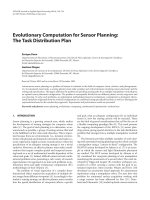
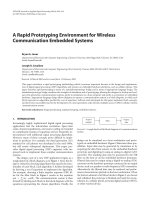
A basic control structure is shown in Figure 1. As the coding
procedure continues, the current FIFO occupation becomes
FIFO
current
= FIFO
previous
+
Coding
bit
− Ta rget
bit
, (1)
where Coding
bit
is the current coding result and Target
bit
is the constant output ra te. Since the coding bit rate may
be larger or smaller than the target bit rate, a FIFO mem-
ory is employed as a regulator to dynamically balance the
An Adaptive Video Coding Control Scheme for Real-Time MPEG Applications 245
Video
sequence
Coding kernel
Coding data
FIFO buffer
Constant
target rate
Coding control
Figure 1: The basic coding control scheme.
coding bit rate and the target bit rate. Because the mem-
ory size is limited, we need to adjust the quantization level
to avoid the buffer to overflow or underflow. In MPEG cod-
ing systems, the fixed group of picture (GOP) structure is
IBBPBBPBBPBBI, where the I-frame is the basic reference
for P- or B-frame coding. P-frame coding uses the motion
prediction from the I-frame or the previous P-frame, and B-
frame coding employs the bidirectional prediction between
the neighboring I-frame and P-frame, or between two P-
frames. Therefore, the total coding bit rate for one GOP is
then the sum of the coding bits of each frame, which is
GOP
bit rate
= I
bit
+P
bit
+B
bit
, (2)
where I
bit
,P
bit
,andB
bit
are the coding bits for the I-frame,
P-frame, and B-frame, respectively.
2.1. A new adaptive GOP structure
When the static GOP structure is used, the coding efficiency
of its P- or B-frames becomes poor for low correlation se-
quences due to high prediction errors. An extreme case is
that if the video sequence changes suddenly, the coded image
may produce serious distortions. On the other hand, wh ile
the temporal correlation among the video fr a mes is high, we
can obtain better performance by applying more P- and B-
frames coding. Hence the coding quality will be much better
since the motion compensation from the previous frame is
done.Thisisparticularlyeffective for low motion sequences.
One of the effective compensation methods is the adaptive
GOP (AGOP), where the structure is dynamically modified
according to the temporal correlation between interframes.
The AGOP concepts are proposed as follows. First, the P-
and B-frames are continuously coded by the prediction mode
until one of the fol l owing conditions occurs:
(i) if the buffer utilization is very low, then the I-frame
will be coded to avoid the buffer underflowing;
(ii) if the video sequence changes suddenly, that is,
P(n)
bit
P(n − 1)
bit
is detected, where P(i)
bit
is the
coding bit rate for the ith P-frame, then we re-encode
the nth frame using an I-frame coding rather than a
P-frame coding;
(iii) if the accumulated error gradually becomes high such
that
P(n)
bit
−1
k=−m
P(n + k)
bit
m
, (3)
the current P-frame coding rate is higher than the averaged
bit rate of the previous m frames and over a predefined
threshold, then the nth frame uses an I-frame coding.
In the above processing, the GOP structure is adaptively
changed in accordance with the temporal correlation of the
previous frames. If the intervening frames have high correla-
tion, we use more prediction coding to reduce the temporal
redundancy until the accumulated error becomes too large
or a scene change is detected. When video sequences go on,
the scene change point may be at the I-, B-, or P-frames. If the
scene change is at the I-frame, the reference memory is reset
by the I-frame itself, and so there will be no problems for the
next P- or B-frame prediction. Since the B-frame has bidirec-
tional prediction, there are no serious errors when the scene
change occurs at the B-frame. However, if the scene change
occurs on a P-frame, the predicted error will be high due to
the lack of temporal correlation. Then the predicted error
will accumulate to the next frame coding and the coding per-
formance thus degrades ser iously. It is a direct method that
we can re-encode the current frame using an I-frame cod-
ing for the off-line system when a scene change is detected or
the temporal correlation becomes very low. However, we also
aim to reduce the processing time as much as possible for the
requirements of real-time applications.
For real-time processing requirements, we monitor the
coding condition using the slice base in the MPEG system.
First, let N be the number of slices used in the coding system.
The first N slices bit rate (slice
first
current
) of the current frame
is then compared with the first N slices (slice
first
previous
)ofthe
previous frame. In addition, let Q
first
current
and Q
first
previous
denote
the averaged quantization scales for the first N slices of the
current and the previous frames, respectively. If the averaged
coding bit rates of the N slices for the adjacent frames have
changed drastically, that is,
Q
first
current
×
slice
first
current
N
Q
first
previous
×
slice
first
previous
N
(4)
indicating that a scene change has been detected between the
current frame and the previous one, then a new intracod-
ing is introduced to process the rest of the current frame.
The same intracoding is then used for the first N slices of the
next frame and its remaining slices return to use the predic-
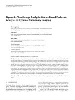
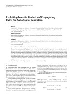
tion coding. Figure 2 shows the detailed frame coding with a
scene change. The comparison begins only when both frames
have P-coding in their first N slices, and the new intracoding
is again introduced when another drastic change has been
detected. Our scheme is hence efficient and fast to satisfy the
needs of real-time processing. Fur thermore, in our experi-
ments, the number of N is not fi xed. The first slice coding
rate is checked, and the scene change is found if the coding
rate of the current frame is the triple of the previous one in
(4). We immediately encode I-mode for the next slices. Oth-
erwise, the first two slices are checked again. With this pro-
cedure, we check the averaged coding bits from the first N
slices to the whole frame.
246 EURASIP Journal on Applied Signal Processing
First N slice
First N slice First N slice
Previous frame n − 1
Current frame n Next frame n +1
Scene change
1-frame coding Predict coding
Figure 2: The frame coding as scene change between (n − 1)th and
nth frames.
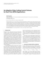
Sequence 1
Sequence 2
BGOP structure AGOP structure AGOP/BGOP BGOP stucture
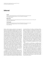
Figure 3: The proposed adaptive GOP structure.
Based on this concept, a new AGOP structure is pre-
sented in Figure 3. First, the basic GOP (BGOP) structure
is employed, consisting of one I-frame, three P-frames, and
eight B-frames, where the frame order is the same as the con-
ventional GOP structure for MPEG systems. Next, an AGOP
structure is applied, whose length depends on the tempo-
ral correlation. Consequently, its length will be considerably
shortened if a scene change is detected. In order to enhance
the advantage of our new coding scheme, there is no I-frame
used in the AGOP structure. We also adopt 12 frames as a
coding unit to keep bit rate balancing. The sequence order is
then
P
e
BBPBBPBBPBBP
e
BBPBB , (5)
where P
e
is an enhanced P-frame with a higher coding bit
rate than that of a normal P-frame. We use a P
e
-frame ra ther
than an I-fr ame for high-correlated video sequences in or-
der to reduce the temporal redundancy and the coding bit
rate. Hence, the total coding efficiency is increased due to
this motion compensation. The AGOP coding scheme ends
when a scene change is detected or the accumulated error
becomes too large, and then the coding procedure begins an-
other BGOP processing.
It is important to note that for AGOP coding, if the cor-
relation of local blocks is very low between two continuous
frames in one sequence, high prediction errors will not only
occur in the current block but also will be transferred to the
next predicted block. To overcome this drawback, we employ
an intrablock coding instead of the interblock coding for low
correlation blocks in local areas. The following criterion can
determine whether or not the current coding block uses an
intrablock coding for P- or B-frames. If the mean absolute
difference (MAD) [12] from the result of motion estimation
is very large, which implies that the predicted error is very
serious, then an I-block coding is employed to reduce the
predicted error. The coding mode for a macroblock can be
determined by
if MAD < Th
0
, MV = 0, then inter (skip) mode
else if Th
0
< MAD < Th
1
, then inter (MC+DCT) mode
else if MAD > Th
1
, MV = 0, then intramode,
(6)
where thresholds were selected such that Th
1
> Th
0
is always
used. If the MAD of the motion estimation is very low and
the motion vector (MV) is zero, this implies that the current
block is almost the same as the referenced one. Then the ref-
erenced block can be duplicated instead of using the current
block coding, so this coding block is assigned as inter (skip)
mode. However, if the MAD result of the motion estimation
is large, we switch from intermode to intramode to avoid high
prediction errors. For fast and instantaneous real-time pro-
cessing, it is necessary to evaluate the block correlation based
on motion estimations first. So the coding mode for the mac-
roblock w ill be selected from either the intramode or the in-
termode to achieve better coding quality for each local block.
2.2. The coding bit rate budget
2.2.1 For BGOP structure
First, we estimate the bit rate for the I-frame coding. Since
the I-frame is the basic reference frame, its coding error
would be accumulated and propagated to the next P- and
B-frames. To reduce the prediction error, we must appoint
higher a bit rate for the I-frame coding. In any case, the cod-
ing bit rate of an I-frame depends on the target rate and the
frame rate of the system. Therefore, the bit rate for the I-
frame must be constrained in a range of
Target Rate
Frame Rate
× IR
H
≥ I
bit
≥
Targ et Rate
Frame Rate
× IR
L
, (7)
where IR
H
and IR
L
denote the maximum and minimum fac-
tors, respectively, which were determined by the buffer status
of the system. As the buffer utilization is high, the coding bit
rate will be reduced accordingly. In order to control the bit
rate in the constrained range, the quantization level for the I-
frame is adaptively adjusted dependent on both the previous
coding results and the buffer status.
The coding status of the system is monitored by a slice-
base method as follows. An initial quantization level is cho-
sen for the first slice coding as
Q
I
0
=
Q
max
+Q
min
2
× k, (8)
where Q
max
and Q
min
are the maximum and the minimum
quantization scale, respectively, and k is a coefficient depend-
ing on the picture type. If the coding bit rate of the nth slice
An Adaptive Video Coding Control Scheme for Real-Time MPEG Applications 247
is in the range of
Targ et Rate
NO slice × Frame Rate
× IR
H
≥ slice
I
n
≥
Targ et Rate
NO slice × Frame Rate
× IR
L
,
(9)
where NO slice is the number of slices in one frame, there
will be no change in the quantization parameter. Otherwise,
the quantization level is adjusted
if slice
I
n
≥
IR
H
× Ta rge t R ate
NO slice × Frame Rate
, Q
I
n+1
= Q
I
n
+1;
if slice
I
n
≤
IR
L
× Ta rge t R ate
NO slice × Frame Rate
, Q
I
n+1
= Q
I
n
− 1;
(10)
where Q
I
n
and Q
I
n+1
denote the quantization scales for the
current slice and the next slice, respectively. If the coding
bit rate is over the predefined levels in the current slice, the
quantization scale is increased or deceased by one level for
the next slice in order to keep the specified bit rate. Hence, the
coding rate can keep a dynamic balance during each frame
coding. The final slice quantization scale is then recorded
as an initial value for the first slice of the next I-frame
coding.
In order to prevent the buffer from overflowing or un-
derflowing, there should be a warning system for checking
buffer status. In our method, the status of the buffer occupa-
tion is not frequently extracted for quantization adjustment.
When the percentage of the buffer utilization P
0
falls in the
range of 0.2 ≤ P
0
≤ 0.8, the buffer operates in normal con-
dition and the quantization level is not adjusted. Otherwise,
the quantization level will be adjusted for the next slice cod-
ing as follows:
if P
0
≥ 80%, Q
I
n+1
= Q
I
n
+2;
if P
0
≤ 20%, Q
I
n+1
= Q
I
n
− 2;
others, Q
I
n+1
= Q
I
n
.
(11)
From (10)and(11), the maximum quantization scale is in-
creased by three when the slice coding rate is over the prede-
fined level and the buffer utilization P
0
≥ 80%. In another
case, when the slice coding is lower than the predefined min-
imum level, but P
0
≥ 80%, we also increase the quantization
scale by one for the next slice coding.
Next, we discuss the rate control for P-frame coding . Be-
cause most of the temporal redundancy for P-frames can be
removed by using motion compensations, the coding bit rate
for the P-frame is not as high as that of an I-frame. The
P-frame bit rate is then chosen close to the target bit rate
with
Targ et Rate
Frame Rate
× PR
H
≥ P
bit
≥
Targ et Rate
Frame Rate
× PR
L
, (12)
where PR
H
and PR
L
denote the maximum and minimum
control rates, respectively, and are usually close to unity. We
also control the bit rate for P-frame coding with slice base,
which can be expressed as
Targ et Rate
NO slice × Frame Rate
× PR
H
≥ slice
P
n
≥
Targ et Rate
NO slice × Frame Rate
× PR
L
.
(13)
Similarly, to the I-frame coding, the quantization level for
each slice of a P-frame is adaptively adjusted
if slice
P
n
≥
PR
H
× Ta rge t R ate
NO slice × Frame Rate
, Q
P
n+1
= Q
P
n
+1;
if slice
P
n
≤
IR
L
× Ta rge t R ate
NO slice × Frame Rate
, Q
P
n+1
= Q
P
n
− 1;
others, Q
P
n+1
= Q
P
n
.
(14)
Hence, during one GOP coding, the total output bit rate
is then
Output
bit rate
=
Targ et Rate × NGOP
Frame Rate
, (15)
where NGOP is the number of frames in one GOP. It is
desirable to control the GOP
bit rate
in (2), very close to the
Output
bit rate
, to obtain a dynamic balance in the entire GOP
coding period. If the GOP
bit rate
is equal to Output
bit rate
,
then
I
bit
+3P
bit
+8B
bit
∼
=
Targ et Rate × 12
Frame Rate
, (16)
that is, the GOP structure is contained in one I-frame, three
P-frames, and eight B-frames, and thus we assume that all P-
and B-frames have the same coding rate. In order to achieve
the dynamic balance, the coding bit rates of B-frames are
adaptively modified to compensate for those of the I- and
P-frames. Since B-frames are not used as references for mo-
tion prediction, the B-frame coding is not as important as
that of the I-frame and P-frames. Moreover, B-frames use
the bidirectional prediction, and so their coding errors will
be smaller. From (9), (13), and (16), the B-frame bit rate is
limited to
Targ et Rate
8 × Frame Rate
×
12 − IR
L
− 3PR
L
≥ B
bit
≥
Targ et Rate
8 × Frame Rate
×
12 − IR
H
− 3PR
H
.
(17)
In order to control the B-frame bit rate, its quantization level
is adjusted in each slice, which is similar to that of the P-
frame coding. Meanwhile, the buffer occupation also must be
periodically monitored during the P- and B-frames coding,
where the control procedure is the same as that of the I-frame
coding.
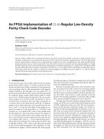
248 EURASIP Journal on Applied Signal Processing
Sequence 1 Sequence 2
Coding bits
Basic GOP AGOP AGOP AGOP Basic GOP
Frame
I
B
B
P
B
B
P
B
B
P
B
B
Pe
B
B
P
B
B
P
B
B
P
B
B
Pe
B
B
P
B
B
P
B
B
P
B
B
Pe
B
B
P
B
B
P
B
B
P
B
B
I
B
B
P
B
B
P
B
B
P
B
B
Figure 4: The ideal buffer occupation in the proposed adaptive GOP.
2.3. For the AGOP
In order to obtain higher coding efficiency, the use of in-
tracoding in the same video sequence should be avoided if
the temporal correlation is high, w hich can be done as fol-
lows. A video sequence can be part itioned into many AGOPs,
and each AGOP consists of 12 frames as a coding unit that
contains one enhanced P-frame (P
e
), three P-frames, and
eight B-frames. The enhanced P-frame is the starting point
for each AGOP. Its position is like the I-frame of a BGOP,
but its coding bit rate is not as hig h as an I-frame, which is
given by
Targ et Rate
NO slice × Frame Rate
× P
e
R
H
≥ slice
P
e
n
≥
Targ et Rate
NO slice × Frame Rate
× P
e
R
L
,
(18)
where PR
H(L)
< P
e
R
H(L)
< IR
H(L)
. Its P- and B-frame cod-
ing rates are similar to (12)and(17), respectively. The P- and
B-coding bit rate may be slightly increased to improve the
coding quality since the P
e
-frame coding rate is usually less
than that of the I-frame. The coding performance of the en-
tire video sequence is then greatly improved from the motion
compensation. The ideal buffer occupation of the proposed
AGOP method is illustrated in Figure 4, where the coding bit
rate can maintain dynamic balance during the entire GOP
coding. However, coding bit rates can vary drastically for dif-
ferent video sequences, so it is not easy to achieve an ideal
buffer occupation for each GOP coding. Hence, we need to
monitor the buffer status at the end of each GOP. If the buffer
is occupied by one half or more at the end of the GOP cod-
ing, the coding rate should be decreased in the next GOP to
achieve the coding bit rate balance.
3. EXPERIMENTAL SIMULATIONS
In order to test the performance of our algorithm, four video
sequences “Football,” “Susie,” “Flower-garden,” and “Sales-
man,” the frame size with 352 × 288 resolutions, were em-
ployed. To simulate the practical video sequences, we pasted
the parts of each sequence together to form a test sequence
as follows. The first 1–50 frames are from the “Football,”
the 51–100 frames are from the “Phone-lady,” the 101–150
frames are from the “Flower-garden,” and finally the 151–200
frames are from the “Salesman.” For comparisons, we also
tested this sequence using the well-known TM5 method
[11].
The simulations were done under the condition of
400 k-bit buffer size, 1.2 M target bit rate, 30 frames per sec-
ond, and the range of the motion search was −16 ∼ +16. The
initial parameters were set at IR
H
= 5, IR
L
= 4.5, PR
H
= 1.5,
and PR
L
= 1.2 for BGOP; and P
e
R
H
= 4, P
e
R
L
= 3.5,
PR
H
= 1.7, and PR
L
= 1.4 for AGOP. These parameters
may have ±10% adjustments according to the buffer status.
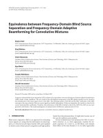
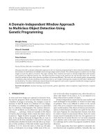
Figure 5a shows the result of coding bit in each frame. In our
scheme, the averaged bit rates of I- and P-frames are larger
than that of the TM5 to reduce the predicted errors; and our
bit rate of the B-frame is less than that of the TM5 to obtain
the coding bit rate balance. Next, we compared the buffer
status, and the results are shown in Figure 5b. In the TM5
method, the bit allocation is not exact for each frame cod-
ing, hence the buffer underflowed during the 158th–165th
frames. In our coding method, since the utility ratio of buffer
is always forced to settle in the range of 80% ∼ 20% occupa-
tion, no underflow or overflow occurred. At the high motion
sequencessuchas“Football”and“Flower-garden,”attimes
the buffer exceeds the utility ratio, but we can prevent the
buffer from overflowing since there is 20% reservation. As
the coding bit rate becomes very high, the quantization level
An Adaptive Video Coding Control Scheme for Real-Time MPEG Applications 249
0 20 40 60 80 100 120 140 160 180 200
Frame number
0
0.5
1
1.5
2
2.5
3
×10
5
Coded bits (bits)
Proposed
TM5
(a) The coding rate for each frame.
0 20 40 60 80 100 120 140 160 180 200
Frame number
−1
0
1
2
3
4
×10
5
Buffer status (bits)
Proposed
TM5
(b) The buffer occupation during 200 frames coding.
0 20 40 60 80 100 120 140 160 180 200
Frame number
20
25
30
35
40
45
PSNR (dB)
Football Susie
Flower-
garden
Salesman
Proposed
TM5
(c) The coding quality estimation for each frame.
Figure 5
was gradually increased for the next slice coding in order to
avoid degradations of the coding quality suddenly. The buffer
occupation was then slowly decreased as the coding contin-
ues. During the 200 frames coding, the final buffer occupa-
tion in our method is almost the same as that of the TM5,
and the coding rate of our method was able to keep balance
throughout the entire processing.
Next, we measured our coding quality using the above
parameters with the results as shown in Figure 5c.Ouradap-
tive algorithm achieved an improvement of about 2 ∼ 5dB
PSNR on the average compared with the TM5 method
for various sequences. The results show that our algorithm
can provide much better quality for low motion sequences
such as “Salesman.” We also notice the performance of the
(a) The decoded 151th image with our
proposed method (PSNR = 35.09 dB).
(b) The decoded 151th image with
TM5 method (PSNR = 23.78 dB).
Figure 6
decoding sequence at the scene change. The decoded frames
are individually shown in Figure 6 using our algorithm and
the TM5 coding at the 151th frame. The TM5 method usu-
ally produces serious distortions in the decoded image due
to high predicted errors at the scene change, but no visi-
ble distortion was found from the reconstructed image by
our method. Moreover, we compare the coding quality be-
tween the I-frame of the static GOP using TM5 method and
the enhanced P-frame of the proposed AGOP. Figure 7 shows
our enhanced P-frame and the decoded I-frame result at the
180th fr a me. Clearly, the proposed rate control scheme can
improve the coding efficiency.
The coding performance is dependent on the reliability
of scene change. To test and compare the function of scene
change, two completing algorithms for scene change were
evaluated [13, 14]. We simulated two programs “Top Gun,”
and “Weather Forecast.” To evaluate the detection perfor-
mance of the scene change, we define a testing parameter as
Reliability =
Nc − Nf
Nc + Nm
× 100%, (19)
where Nc is the number of correct detection, Nm is the
number of missed detections, and Nf is the number of
false detection. In the “Top gun” program, there are 7630
frames, which have 156 scene changes. Another “Weather
Forecast” progr am uses 6760 frames, with 48 scene changes.
250 EURASIP Journal on Applied Signal Processing
Table 1 Comparisons of scene change detection performance.
Methods Kang et al. [13] Huang et al. [14] Proposed
Sequences
Top Gun (7630 frames)
Correct detection
149 150 151
False detection 6 4 9
Missed detection 7 6 5
Reliability 92% 94% 92%
Weather Forecast (6760 frames)
Correct detection 46 47 47
False detection 2 1 3
Missed detection 2 1 1
Reliability 92% 96% 92%
Enlarge
(a) The decoded 180th image with our proposed
method (PSNR = 42.55 dB).
Enlarge
(b) The decoded 180th image with TM5 method
(PSNR = 36.57 dB).
Figure 7
The former has much higher motion and more scene changes
than the later. The results are listed in Tabl e 1 . Simulations
demonstrate that our scene change detection can achieve
about 92% reliability, which is close to the other high-
performance algorithms [13, 14]. For practical video encod-
ing applications, the number of missed detections should
be as low as possible since the coding quality degrades se-
riously if the scene change point cannot be found. So we can
reduce the detection threshold in (4). However, the num-
ber of false detections would be increased, and the length of
AGOP is shortened accordingly. In the worst case, our perfor-
mance is the same as static GOP since the minimum length
of AGOP is set with 12 frames. This is acceptable for practical
coding systems since I-mode coding only increases the cod-
ing bit rate but without serious prediction errors. Moreover,
our scene detection method only extracts the coding param-
eters, that is, slice coding rate and quantization scale, from
the video encoder and adopts a simple analysis to find the
scene change. Hence, the computational complexity of the
proposed scene change detection is clearly lower than that of
the other methods.
4. CONCLUSIONS
In this study, we proposed a novel video coding control algo-
rithm by using an AGOP approach instead of the static GOP
structure. The current temporal correlation between the two
neighboring frames is monitored and used for BGOP/AGOP
switching decision with low computational lo ad to make it
applicable to real-time systems. This is basically done by us-
ing the expensive intramode coding, only if a scene change
is detected or the temporal correlation becomes low. An I-
picture is adaptively replaced by an enhanced P-picture to
improve the coding efficiency. The slice-based coding con-
trol scheme is used to satisfy the real-time coding require-
ments and to avoid re-encoding even if a scene change is
found. Simulations demonstrated that the proposed method
achieves better results than the TM5 model and provides
enough accuracy to detect scene changes.
ACKNOWLEDGMENTS
The author acknowledges the suggestions made by the
anonymous reviewers for improving the paper, and thanks
the National Science Council, Taiwan, (NSC90-2213-E-327-
010) for supporting this research, and thanks Chung-Long
Chen for simulating partial algorithms.
REFERENCES
[1] M. Liou, “Overview of the p × 64 kbits/s video coding stan-
dard,” Communications of the ACM, vol. 34, no. 4, pp. 59–63,
1991.
[2] MPEG-2 video, ISO/IEC DIS 13818-2.
[3] G. Cote, B. Erol, M. Gallant, and F. Kossentini, “H.263+: video
coding at low bit-rate,” IEEE Trans. Circuits and Systems for
Video Technolog y, vol. 8, no. 7, pp. 849–866, 1998.
An Adaptive Video Coding Control Scheme for Real-Time MPEG Applications 251
[4] C.F.ChangandJ.S.Wang, “Astablebuffer control strategy
for MPEG coding,” IEEE Trans. Circuits and Systems for Video
Technolog y, vol. 7, no. 6, pp. 920–924, 1997.
[5] L. Wang and A. Vincent, “Joint rate control for multi-
program video coding,” IEEE Trans. Consumer Electronics, vol.
42, no. 3, pp. 300–305, 1996.
[6] M. R. Pickering and J. F. Arnold, “A perceptually efficient VBR
rate control algorithm,” IEEE Trans. Image Processing, vol. 3,
no. 5, pp. 527–532, 1996.
[7] J. Lee and B. W. Dickinson, “Rate-distortion optimized frame
type selection for MPEG encoding,” IEEE Trans. Circuits and
Systems for Video Technology, vol. 7, no. 3, pp. 501–509, 1997.
[8] S. W. Wu and A. Gersho, “Rate-constrained optimal block-
adaptive coding for digital tape recording of HDTV,” IEEE
Trans. Circuits and Systems for Video Technology,vol.1,no.1,
pp. 100–112, 1991.
[9] H. Sun, W. Kwok, M. Chien, and C. H. John, “MPEG cod-
ing performance improvement by jointly optimizing coding
mode decision and rate control,” IEEE Trans. Circuits and Sys-
tems for Video Technology, vol. 7, no. 3, pp. 449–458, 1997.
[10] T. Chiang and Y Q. Zhang, “A new rate control scheme us-
ing quadratic rate distor tion model,” IEEE Trans. Circuits and
Systems for Video Technology, vol. 7, no. 1, pp. 246–250, 1997.
[11] ISO/IEC-JTC1/SC29/WG11: Test Model 5, MPEG93/N0400,
1993.
[12] H. Gharavi and M. Mills, “Block-matching motion estimation
algorithms-new results,” IEEE Trans. Circuits and Systems, vol.
37, pp. 649–651, 1997.
[13] E. K. Kang, S. J. Kim, and J. S. Choi, “Video retrieval based
on scene change detection in compressed streams,” IEEE
Trans. Consumer Electronics, vol. 45, no. 3, pp. 932–936, 1999.
[14] C. L. Huang and B. Y. Liao, “A robust scene-change detec-
tion method for video segmentation,” IEEE Trans. Circuits
and Systems for Video Technology, vol. 11, no. 12, pp. 1281–
1288, 2001.
Shih-Chang Hsia was born in Yuanlin, Tai-
wan, in 1962. He received the Ph.D. de-
gree from the Depar tment of Electrical En-
gineering, National Cheng Kung University,
T’ai-nan, Taiwan, in 1997. During 1986–
1989, he was an Engineer in the R&D De-
partment of Microtek International, Inc.,
Hsin-Chu. He was an Instructor and Asso-
ciate Professor in the Department of elec-
tronic engineering, Chung Chou Institute
of Technology, dur ing 1991–1998. Currently, he is an Associate
Professor in the Department of Computer and Communication
Engineering, National Kaohsiung First University of Science and
Technology Kaohsiung. His research interests include VLSI design,
HDTV and cable systems, video coding and processing, communi-
cation, and data hiding systems.