EURASIP Journal on Applied Signal Processing 2003:6, 603–614 c 2003 Hindawi Publishing pdf
Bạn đang xem bản rút gọn của tài liệu. Xem và tải ngay bản đầy đủ của tài liệu tại đây (1.01 MB, 12 trang )
EURASIP Journal on Applied Signal Processing 2003:6, 603–614
c
2003 Hindawi Publishing Corporation
A Rapid Prototyping Environment for Wireless
Communication Embedded Systems
Bryan A. Jones
Department of Electrical and Computer Engineering, Clemson University, 202A Riggs Hall, Clemson, SC 29634, USA
Email:
Joseph R. Cavallaro
Department of Electrical and Computer Engineering, Rice University, Duncan Hall, MS 380, 6100 S. Main Street,
Houston, TX 77005, USA
Email:
Received 14 March 2002 and in revised form 13 February 2003
This paper introduces a rapid prototyping methodology which overcomes important barriers i n t he design and implementa-
tion of digital signal processing (DSP) algorithms and systems on embedded hardware platforms, such as cellular phones. This
paper describes rapid prototyping in terms of a simulation/prototype bridge and in terms of appropriate language design. The
simulation/prototype bridge combines the strengths of simulation and of prototyping, allowing the designer to develop and eval-
uate next-generation communications systems, partly in simulation on a host computer and partly as a prototype on embedded
hardware. Appropriate language design allows designers to express a communications system as a block diagram, in which each
block represents an algorithm specified by a set of equations. Software tools developed for this paper implement both concepts,
and have been successfully used in the development of a next-generation code division multiple access (CDMA) cellular wireless
communications system.
Keywords and phrases: design partitioning, rapid prototyping, embedded systems.
1. INTRODUCTION
Increasingly, highly sophisticated digital signal processing
applications fuel the information revolution. Space-time
codes, channel equalization, and source coding are founded
on complicated systems of equations and are frequently in-
terconnected with additional signal processing algorithms.
However, many of these concepts prove difficult to imple-
ment in products. For example, the third generation (3G)
standard for cell phones was developed in the mid-1990s,
but still awaits widespread deployment. This paper pro-
vides digital sig nal processing (DSP) engineers with im-
proved tools to implement these complex communications
systems.
The design cycle of a new DSP application begins as a
roughsketchofablockdiagram,asinFigure 1. Next, the de-
sign is refined by choosing algorithms that specify the func-
tionality of each block. Each algorithm is further developed
by deriving a set of equations to implement the algorithm.
For example, choosing a finite impulse response (FIR) fil-
ter for the filter block in Figure 1 results in the equation
out =
i
in
i
· coeff
i
. The communications system is then
formed by labeling each block in the block diagram with the
equations representing the chosen algorithms. Finally, the
Acquire
samples
Filter
Output
data
Figure 1: A rough sketch of the block diagram of a communications
system.
design can be simulated on a host workstation and proto-
typedonembeddedhardware.Figure 2 illustrates these pos-
sibilities. Input data may be generated by simulation or by
acquiring the data from sensors on the embedded hardware
prototype and digitizing it using an analog-to-digital (A/D)
converter. The resulting data may be processed by the FIR
filter on the host or on the embedded hardware prototype.
Filtered data may be output using a digital-to-analog (D/A)
converter on the hardware prototype connected to an output
device, such as a speaker or radio frequency (RF) transmitter.
Alternatively, the filtered data may be analyzed and perfor-
mance charac teristics plotted on the host workstation. When
the bottom element of all three blocks in Figure 2 are chosen
and validated, the prototype is finished and ready for encap-
sulation in a cellular phone, personal digital assistant (PDA),
or other wireless device.
604 EURASIP Journal on Applied Signal Processing
Acquire samples
Simulate
input data
Or
Sensor
A/D
converter
FIR filter
Executing on host
Or
Executing on
embedded hardware
out =
i
in
i
· coeff
i
Output data
Analyze and
plot results
Or
D/A
converter
Output
device
Figure 2: A fully developed system prepared for simulation on a host workstation to check the system’s performance and correctness, for
execution on embedded hardware to validate the system’s real-world characteristics, or for a combination of both to better analyze the
performance of the system.
Prototype hardware
Sensor
A/D
converter
FIR filter
out =
i
in
i
· coeff
i
Communication link
Host workstation
Analyze and
plot results
Figure 3: A sketch of the system, showing selected blocks executing on the prototype hardware, while the remaining blocks execute on the
host workstation. Note the addition of a communication link, automatically inser ted by the simulation/prototype bridge.
This paper infers two important realizations from the de-
sign cycle. First, the design takes place in two distinct loca-
tions. Because a cellular phone or PDA must be small and
lightweight, its prototype by design contains minimal hard-
ware: a power-efficient DSP and a small display. In contrast,
the system used to design the prototype is usually a power-
ful workstation, with a mouse, keyboard, video display, and
large amounts of storage. Second, the design was specified
using several languages: an equation description language, a
block diagram language, and code in the C language, running
on the DSP in the prototype.
This paper discusses two contributions that enable and
improve the rapid prototyping of communications sys-
tems. First, the simulation/prototype bridge unites a sim-
ulation with a hardware prototype, providing communica-
tions system designers with the combined benefits of both
approaches. Portions of the design used to generate data
and analyze results can be executed on a host computer,
while time-critical blocks execute on a hardware prototype.
Figure 2 shows a block diagram in which the prototype sam-
ples and filters data, then sends it to the host for analysis.
Note the addition of a communication link, automatically
inserted by the simulation/prototype bridge, which connects
the prototype to the host. Second, the use of appropriate lan-
guage design allows the engineer to express each subsystem in
a communications system using the language best suited for
that subsystem. For example, the designer may use Simulink
to draw block diagrams, and Matlab to implement equations
for each block in the block diagram, as illustr ated by the FIR
filter block in Figure 2.
Section 2 discusses previous work in rapid prototyping.
This work presents the simulation/prototype bridge opera-
tion pictured in Figure 3 in Section 3. Section 4 details ap-
propriate language design concepts illustrated by the FIR fil-
ter block in Figure 2.
2. RAPID PROTOTYPING SYSTEMS
Next-generation communications systems promise to de-
liver a wide variety of new features such as improved bat-
tery life, smaller size, full-motion video, and high-bandwidth
Internet connections. Inherent in the design of any such
system is the development and integration of several com-
putationally intensive algorithms which enable these new
features. Two problems hinder designers of these systems.
First, block diagrams and equations compose typical com-
munications systems; however, prototype hardware must
be programmed in C or assembly, an awkward and error-
prone languages in which to implement block diagrams
and equations. Second, designers develop simulations which
execute on a host, while other engineers create hardware
prototypes. However, the host and prototype platforms re-
main isolated from each other; the simulator’s power can-
not be combined with the real-time constraints of the proto-
type.
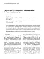
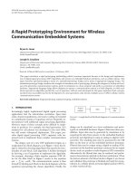
For example, Figure 4 shows a block diagram for a mul-
tiuser receiver, which is a part of a base station in a next-
generation cellular phone network. Each block is annotated
with equations, which specify the algorithm implemented by
that block. Simulation is first used to verify the correct oper-
ation of each block and then of the entire system. Finally, the
system is translated into C or an HDL and compiled to run
on the DSP or FPGA at the heart of the base station proto-
type.
A Rapid Prototyping Environment for Wireless Communication Embedded Systems 605
Antenna
Chip-matched filter
y =
T
r
y = A
T
r
d = sign(y)
L= A
H
1
A
0
C = A
H
0
A
0
+A
H
1
A
1
− diag(A
H
0
A
0
+ A
H
1
A
1
)
y
(l)
i
= y
(0)
i
− Ld
(l)
i−1
− Cd
(l)
i
− L
H
d
(l)
i+1
Multiuser detector
Channel estimator
Detected bits
A
(i)
= A
(i−1)
− µ(A
(i−1)
∗ R
(i)
bb
− R
(i)
br
)
R
(i)
bb
= R
(i−1)
bb
+ b
L
∗ b
T
L
− b
0
∗ b
T
0
R
(i)
br
= R
(i−1)
br
+ b
L
∗ r
H
L
− b
0
∗ r
H
0
Figure 4: An iterative multiuser receiver, represented as a block di-
agram in which each block contains an algorithm specified by a set
of equations.
Unfortunately, the languages and design tools available
today are largely incompatible with each other and are usu-
ally unable to execute both on the host and on the DSP. Mat-
lab, Simulink, and C interoperate poorly, and only run either
on the host or on the prototype. Algorithm designers pre-
fer a powerful programming language such as Matlab which
is tailored to the description of equations. Algorithms writ-
ten in Matlab, however, cannot directly execute on a DSP
though there are several promising papers in this area [1, 2].
Communications system designers prefer a block diagram
entry and simulation package such as Simulink. Like Mat-
lab, Simulink runs only on the host; its ability to integrate
Matlab into algorithm blocks is very poor. C code written
for the DSP typically uses DSP-only libraries, preventing it
from executing on the host. Integrating C code with Matlab
or with Simulink is a difficult task and requires knowledge of
the Matlab C-MEX interface [3] or the Simulink S-function
interface [4].
The monolingual and unilocation nature of today’s lan-
guages and tools limits the complexity of achievable designs.
First, they restrict a designer to the use of only one language
for the entire design though the use of an alternate language
for parts of the design is preferable. Second, today’s languages
and tools force the designer to rewrite the entire design
when moving between languages or locations. Finally, mod-
ern languages and tools isolate the host-based simulation
environment from the DSP-based execution environment.
Real-time data acquired by the prototype hardware cannot
be easily passed back to the host for analysis; likewise, simu-
lated data generated on the host cannot be processed on the
prototype.
Similar to other coordination languages such as
Simulink, the Ptolemy project [5] provides a coordination
langauge which enables the simulation and prototyping of
heterogeneous systems. A team of researchers at the Univer-
sity of California-Berkeley developed this system in the early
1990s; material in this section is based on their work [5].
Ptolemy supports heterogeneous systems by allowing blocks
with differing computational models, or domains, to coexist
in a single system. For example, a filtering block in a signal
processing domain expects a single input and calculates a
single output at a constant rate. In contrast, a queuing block
in a networking domain accepts a variable number of inputs
and executes only when a downstream block pulls data from
its queue.
The Ptolemy project primarily focuses on the develop-
ment of a coordination langauge, which is implemented as
a set of C++ classes. New computational models may be de-
veloped by inheriting from the appropriate base classes, then
writing appropriate code for the new model. Unlike the work
in this paper, it does not provide a bridge between a simu-
lation executing on the host and a prototype executing on a
DSP. In addition, Ptolemy exclusively relies on C++ rather
than providing appropriate language design as discussed in
this paper.
2.1. Applications
The following concepts developed in this paper improve the
design process for communications systems. First, the speci-
fication of a system using languages appropriate for each sub-
system of the design improves the robustness, modularity,
and abstraction of the design. These three attributes create
opportunities for extensive optimization. Second, the use of
a simulation/prototype bridge combines the real-time, real-
world behavior with the powerful analytical tools of a simu-
lation environment.
Appropriate language design encourages robust design
practices. Concise descriptions of a concept are possible us-
ing a language designed to express the concept. For exam-
ple, drawing a state machine diagram allows a clearer, more
compact description than a large switch statement with many
cases in a traditional programming language. Second, a con-
cise description better illustrates the purpose of the design
both to the designer and to other designers planning to use
or improve the design. Finally, appropriate language design
shortens the development cycle by providing debugging and
analysis tools tailored for the design. The Matlab debugger,
for example, allows the user to halt a program and perform
complex analysis of the code. Displaying the norm of a ma-
trix or plotting the Fourier transform of an intermediate re-
sult is simple. Performing the same analysis in C is difficult,
if not impossible.
Appropriate language design also encourages modular
design practices. Because the language is suited for the de-
sign, the designer is able to naturally divide the design into
modules. The language’s calling conventions guarantee that
each module will have a standardized interface, encouraging
reuse. Simulink, for example, divides a design captured as a
block diagram into a set of blocks. Designers can easily re-
place one block, such as a filter, by an improved filter.
Finally, appropriate language design encourages the de-
signer to focus on the design though the use of abstraction.
The languages free the designer from unnecessary complexity
by providing high-level abstraction for complex operations.
606 EURASIP Journal on Applied Signal Processing
For example, the details of a matrix multiply or the mechan-
ics of block scheduling are handled by Matlab and Simulink,
respectively. In addition, Matlab’s interpreter allows the user
to call powerful analysis functions such as fast Fourier trans-
forms (FFTs) during the debug process, while C’s compiled
nature prevents such flexibility. Like Artemis [6], the use of
Matlab’s high-level features allow design exploration at the
algorithm level before writing architecture-specific C code to
efficiently implement each block.
Robust, modular, abstracted language design enables the
use of many powerful optimization techniques. Applications
of these optimizations to block-diagram languages and to
equation-description languages such as Simulink and Mat-
lab are reviewed below.
The separation of tasks into a series of interconnected
blocks in a block diagram allows the designer to naturally ex-
press parallelism in a design. The design can then be sched-
uled on a heterogeneous multiprocessor system using tech-
niques detailed by Bhattacharyya [7]. Alternatively, the de-
sign can b e optimized for a VLIW architecture with perfor-
mance approaching that of a highly complex superscalar pro-
cessor using thread-parallel techniques [8, 9].
By specifying each block as a set of linear equations, op-
timization techniques specific to linear algebra can be ap-
plied. Methods in [10, 11, 12] demonstrate significant perfor-
mance improvements. In addition, the application of fixed-
point techniques [13] to the equations trade a small decrease
in accuracy for a significant performance increase.
The goal of both appropriate language design and a
simulation/prototype bridge is the development of advanced
communications systems. Section 5 discusses the accom-
plishment of this goal in the design of a next-generation code
division multiple access (CDMA) cellular communications
system.
3. SIMULATION/PROTOTYPE BRIDGE
This section discusses the development of a simulation/pro-
totype bridge. The bridge unifies the simulation and pro-
totyping worlds, enabling engineers to develop larger,
more complex communications systems. The computational
model assumed by simulators and by prototyping environ-
ments explain the disconnect between the two approaches.
Simulators operate under the assumption that the host com-
puter’s CPU is the sole resource for performing signal pro-
cessing. Matlab [14], Simulink [15], SPW [16], and the
Cocentric System Studio [ 17] all follow this model. Though
most of these packages can produce an executable for a pro-
totype, the resulting executable has little ability to commu-
nicate with the original simulation. Prototyping systems, in
contrast, assume that the prototype hardware must execute
all signal processing operations on the prototype. Prototyp-
ing systems utilize a desktop computer as a terminal on
which to display the state of the prototype for diagnostic pur-
poses.
Changing this computational model requires the parti-
tioning of a design between the desktop, or host, and the
prototype so that portions of the design can be run on both.
Antenna
A/D sampling
Downconversion
Chip-matched filter
Channel
estimator
Multiuser
detector
Detected bits
Legend:
Runs on prototype
Runs on host
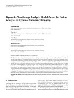
Figure 5: A CDMA baseband receiver, represented as a directed
graph in which each node represents signal processing and each di-
rected edge represents communication.
Given a partitioned design, code in each partition must be
then compiled for execution on the appropriate processor.
Finally, communication links across partitions must be in-
serted to enable the par titions to pass input and output sig-
nals to each other.
The simulation/prototype bridge developed in this paper
provides the ability to partition a design, then automatically
insert appropriate communication links into it. The bridge
provides a graphical user interface (GUI) for partitioning
and allowing the user to label portions of the design for ex-
ecution on either the host or the prototype. Given this la-
beling, it then partitions the design into a host design and a
prototype design. Next it automatically inserts communica-
tion links to connect the two designs. Finally, it compiles the
design, downloads the resulting executable to the prototype,
and begins the joint host/prototype simulation.
3.1. Methodology
Given a design labeled with execution locations, such as
“runs on host” or “runs on prototype,” partitioning the
design and inserting communication links can be viewed
as a graph cutting problem. Consider a design composed
of a number of appropriately interconnected subdesigns.
For example, a typical CDMA baseband receiver includes
a chip-matched filter, an estimator, and a detector. This
design can be drawn as a directed graph, as in Figure 5.
In this graph, which may contain cycles, nodes represent
computation such as signal processing and edges represent
communication between nodes. Partitioning a graph into
host and prototype sections is equivalent to cutting the
graph into partitions by grouping like nodes together as
in Figure 6 . That is, host nodes are collected in a partition
of the graph, while prototype nodes are collected in one
separate partition. All edges which cross the cut from one
partition to another indicate places at which communica-
tions links, represented as nodes in the graph, must be in-
serted, as in Figure 7. Given this partitioned graph with in-
serted communications nodes, each partition can then be
compiled and downloaded for execution on the host and
prototype.
A Rapid Prototyping Environment for Wireless Communication Embedded Systems 607
Antenna
A/D sampling
Downconversion
Multiuser detector
Graph cut
Chip-matched filter
Channel estimator
Detected bits
Legend:
Runs on prototype
Runs on host
Figure 6: The directed graph of a CDMA baseband receiver after
partitioning.
Antenna
A/D sampling
Downconversion
Multiuser detector
Graph cut
Chip-matched filter
Channel estimator
Detected bits
Legend:
Runs on prototype
Communication link
running on prototype
Runs on host
Communication link
running on host
Figure 7: The directed graph of a CDMA baseband receiver after
partitioning and communication link insertion.
To apply this algorithm to a design, the design must first
berepresentedasagraphcomposedofcomputationnodes
and communication edges. The system presented in this sec-
tion takes the advantage of the natural block-diagram rep-
resentation of the design. This allows the user to easily la-
bel each block in the block diagram for partitioning. Finer-
grained graphs of the design can be produced by applying a
number of techniques to transform the functions underlying
each block into a graph. Hardware/software codesign algo-
rithms [7, 18] can be used to provide an automatic labeling
of the design.
3.1.1 Label determination in hierarchical
block diagrams
The model used to partition a design into host and pro-
totype groups relies on representing the design as a graph.
While block-diagram languages such as Simulink, SPW, and
the Cocentric System Studio present a graph-like interface to
the user; they also allow the entr y of hierarchical block di-
agrams. That is, each block in the block diagram may con-
Transmitter Channel Receiver Detected bits
Chip-matched filter
Multiuser
detector
Code-matched filter
1
2
3
4
Parallel interference
cancellation
Legend: Runs on prototype Runs on host Unspecified
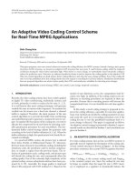
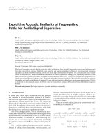
Figure 8: A three-level hierarchical block diagram, showing the
child blocks contained by their parents blocks. Dotted lines indicate
the connection between a parent and its children. Numbers show a
hierarchical traversal of the diagram. Shading and double lines indi-
cate labels of “runs on prototype” and “runs on host,” respectively.
tain an underlying block diagram as illustrated in Figure 8.
This difference in representing the design leads to two diffi-
culties. First, labels of parent blocks must be carefully prop-
agated to each of the child blocks contained by the parent.
Second, all graph-oriented operations performed on the de-
sign must correctly handle the hierarchical structure of the
design.
As shown in the hierarchical block diagram in Figure 8,
some blocks may not be labeled. Others such as the multiuser
detector may be labeled, but contain unlabeled blocks such as
the code-matched filter, or blocks with a different label such
as the parallel interference cancellation block. These difficul-
ties require an algorithm to correctly and consistently prop-
agate labels from parent to child in a hierarchical block di-
agram. The algorithm developed in this paper only assigns
labels to unlabeled child blocks, leaving the labeling of la-
beled child blocks unchanged. Therefore, the algorithm re-
solves the conflicts given in the above examples in the follow-
ing manner. The code-matched filter block, originally unla-
beled, is assigned the “runs on host” label of its parent. The
parallel interference block, labeled “runs on prototype,” re-
mains unchanged.
There are two approaches to overcome this second prob-
lem. First, a graph flattening algorithm can be used to remove
the hierarchy in the block diagram by replacing all parent
blocks with the child blocks they contain. Second, Figure 8
demonstrates a depth-first walk of the diagram from a child
block to its connecting child block, skipping all interven-
ing parents, effectively traversing the hierarchy as if it were
a flattened, single-level graph. In the figure, the walk pro-
ceeds directly from position 1, the output of the channel,
directly to position 2, the input of the chip-matched figure,
instead of simply moving to the parent receiver block. Like-
wise, the walk moves upward from position 3, the output of
the parallel cancellation block, to position 4, the output of
the multiuser detector. Because the multiuser detector is the
final block in the second level, the walk then proceeds to the
output of the receiver. When flattened, a large design may
608 EURASIP Journal on Applied Signal Processing
contain hundreds of blocks, all moved to a sing le level of the
diagram.Thismassofblocksisdifficult for a user to under-
stand or easily navigate. Therefore, this work applies the sec-
ond approach, a depth-first walk of the hierarchy, in all the
algorithms developed in it.
A Matlab function was developed to propagate labels and
perform a depth-first walk of the hierarchical block diagram.
A GUI allows the user to choose a Simulink block diagram,
then click a button to perform label propagation and a depth-
first walk of the block diagram. The Matlab langauge was
chosen because it provides built-in functions for manipulat-
ing a Simulink block diagram; in contr ast, Simulink’s coordi-
nation langauge cannot operate on Simulink block diagrams.
The function propagates labels in the block diagram using
the method discussed above. To reduce execution time, the
function does not propagate labels to every child in the de-
sign. Instead, it stops at the lowest level at which a label was
found, because the labeling for all lower blocks depends only
on the label of the lowest labeled block.
3.1.2 Identifying communication edges
Given a complete labeling of the block diagram, communi-
cation edges which cross from one partition to another must
then be identified. To identify these edges, a Matlab function
examines each labeled block in the block diagram. For each
labeled block, the function walks through each communica-
tion edge leaving the block. For each of these edges, the func-
tion looks at the label on the block this communication edge
connects to. If the label of this destination block differs from
the label of the source block, the function adds this commu-
nication edge to the list of partition-crossing edges. Figure 6
illustrates a group of communication edges which cross the
partition.
Information for future communication block insertion
must also be recorded for each of these partition-crossing
edges. First, the size of data carried on this edge must be dis-
covered. For example, the matrix or vector dimensions must
also be determined for edges carrying matrix or vector data.
Second, the type of data carried by the edge, such as floating-
point or fixed-point, must be stored. Finally, an algorithm
must ascertain the rate at which data passes through the edge
in elements per second. For example, a communication edge
might carry a 3
× 3 matrix of double-precision floating-point
data at a rate of 5 matrices per second. A Matlab function
which gathers the information listed above from a Simulink
block diagram, was written and is detailed in Section 5.
3.1.3 Partitioning of the labeled block diagram
With the original, labeled block diagram and a list of
partition-crossing communication edges, an algorithm can
then divide the diagram into a set of partitioned block dia-
grams, creating one block diagram for each partition. To cre-
ate each of these partitioned block diagrams, the algorithm
first copies the original block diagram. It then removes all
blocks from this diag ram which do not belong to the current
partition based on the labeling of each block. Next, the algo-
rithm inserts communication links for each communication
edge crossing into or out of the current partition, producing
Antenna
A/D sampling
Downconversion
12
3
4
5
6
7
8
Multiuser
detector
Chip-matched filter
Channel estimator
Detected bits
Block diagram executing on prototype
Legend:
Communication link
running on prototype
Block diagram executing on host
Communication link
running on host
Figure 9: The block diagram from Figure 5, from which blocks not
part of each partition have been removed and to which appropriate
communication links have been inserted. Both the host and proto-
type diagrams are shown.
a resulting partitioned block diagram. Figure 9 illustrates this
process.
Communication link insertion requires careful attention.
First, the algorithm must insert the correct type of link. A
link may transmit data from the host block diagram to an
adjacent link as in items 4 and 6 of Figure 9,oritmayre-
ceive data and inject this received data into the prototyp e
block diagram as in items 3 and 5 of Figure 9. Items 1, 7,
2, and 8 of the figure illustrate the opposite case of trans-
mitting from the prototype to the host. In addition, each
communication link must be properly configured with the
size, type, and rate infor mation gathered from the partition-
crossing communication edge, as discussed in Section 3.1.2.
Given this information, the links correctly unite the parti-
tioned block diagram into the original joined block diagram,
while also distributing execution of the block diagram across
heterogeneous processors. Finally, the four communication
links identified above require host- and prototyp e-specific
routines. Communicating with a prototype connected to the
host via a PCI bus differs from communicating over an Eth-
ernet connection.
Matlab functions were written to create the partitioned
block diagrams, then to insert and configure communica-
tion links. The function supports dividing the block dia-
gram into an arbitrary number of partitions. For example,
a multiprocessor prototy pe requires one block diagram per
processor and one block diagram for the host. The function
supports communication link insertion between the Lyr Sig-
nal Processing Signal Master prototype [19] and a Microsoft
Windows-based host. Other communication links, such as a
link between a Sundance Multiprocessor Ltd. PCI-based pro-
totype and a Windows host [20, 21] were developed as a part
of this research; however, they are not yet supported by the
bridge.
A Rapid Prototyping Environment for Wireless Communication Embedded Systems 609
3.1.4 Compilation and execution of the partitioned
block diagram
The final step in the process of building a simulation/proto-
type bridge is to compile the partitions, then to jointly exe-
cute each partition of the block diagram. Like many simula-
tors, Simulink requires that all blocks used in standard host-
based simulation be compiled. Given these blocks compiled
for the host, Simulink dynamically links them together dur-
ing simulation initialization. Via the MathWorks Real-Time
Workshop (RTW) [22] and the Target Language Compiler
[23], Simulink also supports generating a statically-linked C
program from a block diagram. Then, RTW compiles this
program using a prototy pe-specific compiler, such as Code
Composer Studio, TI’s C6x DSP compiler, and development
environment. When the host block diagram is executed, the
communication link sends the resulting compiled code to
the prototype during simulation initialization, correctly syn-
chronizing execution of the host and prototype.
4. APPROPRIATE LANGUAGE DESIGN
When developing new communications systems, designers
cannot assemble these new systems based on libraries of algo-
rithms developed for previous-generation systems. Instead,
they must develop and implement new algorithms which can
then form the building blocks of next-generation systems.
Appropriate language design enables designers to create such
next-generation communications systems and develop new
algorithmic building blocks in a concise, clear form which
encourages modularity and shortens the development cy-
cle. Appropriate language design also provides compilers and
hardware synthesis tools with additional information about
the design, allowing them to produce better optimized, more
efficient code. These two benefits enable the design of larger,
more complex communications systems while reducing the
time spent developing and debugging the design. T he design
of an example communications system shown in Figure 4 il-
lustrates these principles.
The following section discusses methods which enable
appropriate language design in Simulink, a block diagram
coordination language by integrating both C and Matlab
functions into Simulink blocks. Three barriers must be over-
come to accomplish this integration. First, a number of
Simulink block features, such as the number and type of in-
put p orts, output ports, and states, must be specified. Sec-
ond, a mapping between each Simulink block feature and a
C or Matlab variable must be established. Finally, translation
code between Simulink and C or Matlab must be inserted in
order for the two to pass data between each other. Although
all three bar riers can be overcome by writing C code, the pro-
cess is error-prone, time consuming, and difficult.
4.1. Methodology
Integrating C or Matlab into a new user-defined block of a
block diagram coordination langauge such as Simulink re-
quires creating a mapping between the two languages. Func-
tion parameters in Matlab, for example, might be mapped to
block inputs or outputs in Simulink. Before examining this
mapping process, this paper first examines the specification
of features which require mapping in both C, Matlab, and
Simulink. Next, this section examines the mapping process
and presents a methodology to perform this mapping. Fi-
nally, this work presents a translation process to convert from
Simulink data structure to C or Matlab data structures.
4.1.1 Features requiring mapping
A Simulink block is composed of input ports, output ports,
parameters, and states. Simulink, like other coordination lan-
guages, requires specification of three properties of each in-
put and output port. The dimensionality of each port, type
of data such as real or complex, fixed-point or floating-point,
and rate of operation of the port must all be specified. For ex-
ample, an input port may expect a matrix of floating-point
values at a rate of 5 matrices per simulation time step. The
dimensionality and type of parameters may optionally be
specified. Similar to input and output ports, variables local
to each instantiation of a block in a block diagram, termed
states, require specification of the dimensionality and ty pe. In
addition, the number of ports, parameters, and states must
be specified.
In contrast, Matlab and C functions contain only func-
tion parameters which require mapping. In Matlab, input pa-
rameters are distinct from output parameters, while in C they
may be mixed. Matlab enforces no compile-time ty pe check-
ing of parameters although many Matlab functions perform
runtime parameter checking. In contrast, the C langauge is
strongly typed so that the type of each parameter must match
the type specified in the function prototype at compile time.
However, neither C nor Matlab supports specifying or check-
ing the dimensionality of dynamically dimensioned arrays,
such as matrices or vectors. In addition, neither Matlab nor
C specifies rate information for their parameters.
Therefore, the information necessary in specifying Mat-
lab or C function parameters insufficiently specifies the
characteristics of a Simulink block. However, sp ecifying a
Simulink block’s characteristics completely specifies the na-
ture of every Matlab or C parameter though it does not spec-
ify the ordering of parameters in the Matlab or C function
call. Completely specifying both the Simulink block and the
Matlab or C function contained in the block requires speci-
fying the characteristics of the Simulink block and the order
of parameters in the Matlab or C function call.
4.1.2 Mapping between Simulink and C/Matlab
To map between a set of C or Matlab function parameters
and a Simulink block, each parameter must be matched with
an input or output port, a parameter, or a state. In addition,
the dimension, type, and rate of e ach Simulink element must
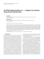
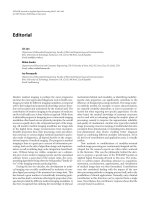
be specified. Figure 10 illustrates mapping a Matlab function
implementing a 16-tap FIR filter to a Simulink block.
This paper performs this mapping by naming both
Simulink elements, such as ports and parameters, and Mat-
lab or C function parameters in a function call, as illus-
trated in Figure 10. T his naming defines the mapping; for
610 EURASIP Journal on Applied Signal Processing
The FIR filter block
d: input port 1, a scalar
(1-element vector)
of floating-point data
f: output port 1, a scalar
of real floating-point data
Function [f, taps] = filter (d, taps, filterCoeffs)
taps = [d taps (1:15)];
f = taps .* filterCoeffs;
Taps: state 1, a 16-element
vector of real floating-point data.
FilterCoeffs: parameter 1,
a 16-element vector
of real floating-point data
Figure 10: A Simulink block demonstrating the mapping of a Matlab function implementing a 16-tap FIR filter to the Simulink block.
Arrows indicate the mapping from block elements to Matlab function parameters. A dotted line differentiates the Matlab function from the
Simulink block elements.
example, “taps” in the figure refers to a real floating-point
16-element vector of block local data, or state, associated
with the Simulink block, and also to both an input and out-
put to the Matlab filter function.
4.1.3 Translation between C or Matlab and Simulink
After a mapping from Simulink block elements to Matlab or
C function parameters has been established, translation of
the data structures used by Simulink and those used by C
and Matlab may be necessary. The matrices and vectors used
by input ports, for example, are stored as a vector of point-
ers, each element of which points to an element of the input
vector or matrix. A C function can correctly dereference this
structure; however, a Matlab function cannot. Therefore, a
translation step must occur when passing a Simulink input
port to a Matlab function parameter. Likewise, Simulink pa-
rameters are stored as Matlab matrices; translating these to a
pointer to the actual matrix data makes accessing the data in
a C function easier for the C programmer.
4.2. Implementation
Enabling appropriate langauge design in the Simulink envi-
ronment by integrating C or Matlab functions into Simulink
blocks is then carried out in three steps. First, the features
requiring mapping, must be gathered such as the names
and specifications of all Simulink block elements and the
function-call syntax of the C or Matlab function being in-
tegrated. Second, a program must perform the mapping be-
tween the Simulink block and the C or Matlab function based
on the names defined in the first step. Third, any necessary
translation code must be inserted between Simulink and the
C or Matlab function.
A Java program was written to accomplish all three steps.
A short Matlab function and a Simulink model were also
written to smoothly integrate this functionality into the
Simulink GUI. The following sections discuss the techniques
used in this paper to accomplish these tasks. See [24]forex-
amples demonstrating the use of this GUI.
4.2.1 Feature specification using a GUI
As described in Section 4.1.1, Simulink block elements, such
as input ports, output ports, parameters, and states, require
specification of the dimensionality, type, and rate of each el-
ement. Matlab and C functions require specification of the
function call’s order of parameters. The program developed
as a part of this research presents a GUI to the user, al-
lowing easy entry of this data. Dialog boxes enable entry of
Simulink block elements. These boxes require the user to at-
tach a unique name to each block element in order to provide
the mapper with a name for each element. A text entry area
provides the user with space to enter the Matlab or C func-
tion call, including all its parameters in a proper order, being
interfaced to the Simulink block.
Given this data, the program can then perform feature
specification of the Simulink block and of the C or Matlab
function. A simple call of the function with the given pa-
rameter carries out all necessary feature specification in C
or Matlab. However, the process of specifying information
about the type, dimension, and rate of each port, state, and
parameter is complex. The following sect ion outlines this
process.
4.2.2 Feature specification in Simulink
The S-function interface [4] specifies a standardized method
for describing the ports, states, and parameters of a Simulink
block. To describe a block, the programmer writes a C pro-
gram containing specifically named functions according to
the S-function specification. During simulation initializa-
tion, Simulink calls these functions to determine the num-
ber and nature of ports, states, and parameters. Within these
initialization functions, the progra mmer then calls Simulink
library routines with parameters which give information
about ports, states, and parameters.
Although Simulink also supports describing a block in
a Matlab scr ipt, this Matlab interface to Simulink is lim-
ited in several important ways. For example, only one input
port can be specified, and the data type of the port cannot
A Rapid Prototyping Environment for Wireless Communication Embedded Systems 611
be specified. For these reasons, this paper prefers the more
powerful C interface, then embeds functions such as filter
from Figure 10 in calls to the Matlab engine from C.
Therefore, specifying Simulink features based on infor-
mation entered by a user into the program’s GUI requires
generating code for a number of C functions. To facilitate
this code generation process, the program is composed of
Java classes to represent every feature in a Simulink block.
A code generation framework then visits each of these classes
and invokes methods from the CodeGen interface to generate
the appropriate C code to specify each feature.
4.2.3 Name-based mapping
Given names of each Simulink block element and a C or
Matlab function call to invoke, the program can map from
each block element to a function call parameter. First, how-
ever, the program must parse the function call to discover
the names used in the call. A parser, included in the pro-
gram, performs this function. For each name discovered in
the function call, the program searches its list of Simulink
block elements. When a match is found, the program gener-
ates C code to transfer data from Simulink to the inputs of the
function, or from function output back to Simulink. For ex-
ample, a call to ssGetInputPortRealSignalPtrs fetches
a pointer to an input por t of real-valued, floating-point data.
Likewise,acalltossGetOutputPortRealSignal fetches a
pointer to an empty area in which a C or Matlab function will
place its real-valued, floating-point output data. The pro-
gram uses a hash table to reduce the time spent in searching
the table.
4.2.4 Insertion of translation code
With the mapping completed, the program next inserts any
necessary translation code. It translates Matlab matrices to a
pointer for C functions and translates input and output ports
to Matlab matrices for Matlab functions. For Matlab func-
tions, the program also inserts a C call to the Matlab func-
tion via the mxCallMATLAB library routine provided by the
CMEX interface [3, 25]. This allows the user to use the stan-
dard Matlab development and debug environment when in-
serting Matlab functions in Simulink blocks. Alternative ap-
proaches, such as compiling the Matlab function to C via the
MCC compiler [26], do not allow this flexibility.
5. TESTBED
The Rice Everywhere NEtwork (RENE) project [27]involves
the development of next-generation algorithms and archi-
tectures targeted at enabling smooth deployment of high-
bandwidth multimedia content wirelessly available at home,
outdoors, and at the office. The RENE team chooses the
CDMA scheme to carry this data for outdoor users and con-
tinues to actively develop extension to this access scheme.
To enable development of these new algorithms and ar-
chitectures for CDMA, a simulation testbed was created in
Simulink [28], as shown in Figure 11.
To further extend the CDMA testbed and to enable the
rapid de velopment of future algorithms, the concepts devel-
oped in this paper were applied to the testbed. Figures 12
and 13 illustrate the results of the Switcher, a program in-
tegrated into the Simulink environment which implements
the simulation/prototype bridge. The Switcher divides the
CDMA testbed into two separate block diagrams, one which
executes on the host (Figure 12) and another which executes
on the DSP (Figure 13). In this example, the blind adaptive
minimum mean square error (MMSE) detector block and
the channel estimation block were chosen to execute on the
DSP, while all other blocks execute on the host. Therefore, the
host block diagram shown in Figure 12 consists of the blocks
in the original block diagram shown in Figure 11 minus the
detector and the estimation blocks. These two blocks appear
only in the DSP block diagram illustrated in Figure 13.Com-
munication links, consisting of the input and output ports in
the DSP block diagram and of the gateway block in the host
block diagram, also appear in the separated system in order
to correctly link the two together.
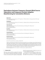
Moving to the design of the blind MMSE detector block,
Figures 14 and 15 show the application of appropriate-
language design discussed in Section 4,inwhichanMMSE
detector written in C [13] is “wrapped” into a Simulink
block. Figure 14 shows the Wrapper’s GUI which is used to
specify the type and size of the input ports, output ports,
and parameters, similar to the FIR filter’s d, f, taps,and
filterCoeffs shown in Figure 10. Figure 15 shows a C
function call implementing the MMSE detector, correspond-
ing to the Matlab code placed inside the dashed box of
Figure 10.
The examples demonstrate the utility of both the con-
cepts and the associated software. Both the Wrapper and
the Switcher programs for Simulink are available for evalua-
tion at />Rapid
Prototyping/rapid prototyping.html.
6. CONCLUSIONS
This paper presents two important concepts which en-
able the rapid prototyping of communications systems. The
simulation/prototype bridge provides the ability to arbitrar-
ily distribute the execution of a Simulink block diagram be-
tween the host and multiple DSPs in a hardware prototype.
This flexibility joins the strengths of simulation with the
strengths of prototyping, enabling designers to make rapidly
and smoothly transition from the simulation of a new com-
munications system to a working prototype of the system.
The use of appropriate language design by inserting blocks
written in C or Matlab into a Simulink block diagram pro-
vides the engineer with the ability to develop new algorithms
in a language best suited for the algorithm, then r apidly in-
tegrate these algorithms in a block diagram. In addition, ap-
propriate language design encourages modularity by encap-
sulating new algorithm in blocks, which can then be easily
reused in a different block diagram. Appropriate language
design encourages design clarity. The equations underlying
612 EURASIP Journal on Applied Signal Processing
CDMA uplink/downlink simulation
Bandband data
Original bits
5
Baseband
data generation
Chip MF
Chan i/p
chip MF o/p
Blind adaptive MMSE
detector [downlink] (C)
Blind adaptive MMSE
detector downlink (C)
User 1 detected
Detected bits
Original bits
User 1 original
Error rate user 1
5
3
BER calculation
Channel estimation
Max likelihood
channel est.
22320
User 1 detected
User 1 original
Error rate
user 1
0
User 1 display:
error rate
#errors
#bits
3
3
Update parameters Show states Compute delay
Figure 11: The RENE CDMA testbed, which performs CDMA uplink and downlink simulations.
CDMA uplink/downlink simulation
Bandband data
Original bits
5
Baseband
data generation
Chip MF
Chan i/p
chip MF o/p
Blind adaptive MMSE detector do
[Blind adaptive MMSE detector do 1]
From
User 1 detected
Detected bits
User 1 original
Original bits
5
Errorrateuser1
3
BER calculation
User 1 detected
User 1 original
Error rate
user 1
3
0
3
User 1 display:
error rate
#errors
#bits
Update parameters
Show states Compute delay
Blind adaptive MMSE detector do
From 1
S
demo 1-DS
Gateway
[Blind adaptive MMSE detector do 1]
Goto 1
Figure 12: The host portion of the RENE CDMA testbed after separation by the Switcher.
A Rapid Prototyping Environment for Wireless Communication Embedded Systems 613
CDMA uplink/downlink simulation
[Chip MF]
From
Blind adaptive MMSE
detector [downlink](C)
Blind adaptive MMSE
detector downlink (C)
BER calculation
Goto
Channel estimation
Max. likelihood
channel est.
1
In
[Chip MF]
Goto 1
[BER calculation]
From 1
1
Out
Figure 13: The DSP portion of the RENE CDMA testbed after sep-
aration by the Switcher.
Figure 14: The GUI used to specify the type and sizes of in-
put/output ports and parameters of an MMSE detector when
“wrapping” the detector into a Simulink block. It implements the
concepts discussed in Section 4.
Figure 15: The GUI used to specify a C function call which im-
plements an MMSE detector when “wrapping” the detector into a
Simulink block. It implements the concepts discussed in Section 4.
algorithms written in Matlab can be simply expressed and
well documented with Matlab’s rich set of mathematical op-
erators. Finally, Simulink clearly captures the overall struc-
ture of a design in a simple block diagram.
In addition, this paper also applies the simulation/proto-
type bridge and appropriate language design to the design
of a next-generation CDMA cellular wireless communica-
tions system. Two software tools, implementing these con-
cepts, allow the designer to rapidly prototype the CDMA sys-
tem, then evaluate its performance in simulation and on a
DSP.
The research presented in this paper can be extended in
a number of directions. One promising area for both the
simulation/prototype bridge and appropriate language de-
sign is an extension of these concepts and implementations
to support FPGAs and ASICs. The ability to efficiently com-
pile Matlab code for DSPs would significantly enhance the
power of appropriate language design.
ACKNOWLEDGMENTS
This work was supported by Nokia, Texas Instruments, the
Texas Advanced Technology Program under Grant 1999-
003604-080, and the National Science Foundation under
Grant ANI-9979465.
REFERENCES
[1] P. Banerjee, N. Shenoy, A. Choudhary, et al., “A MATLAB
compiler for distr ibuted heterogeneous reconfigurable com-
puting systems,” in IEEE Symposium on FPGA Custom Com-
puting Machines (FCCM ’00), pp. 39–48, Napa, Calif, USA,
April 2000.
[2] L. DeRose, K. Gallivan, E. Gallopoulos, B. Marsolf, and
D. Padua, “FALCON: An environment for the development
of scientific libraries and applications,” in Proc. 1st Interna-
tional Workshop on Knowledge-Based System for the (re)Use of
Program Libraries (KBUP ’95), pp. 149–160, Sophia Antipolis,
France, November 1995.
[3] The MathWorks, Natick, Mass, USA, Application Program In-
terface Reference, June 2001, revised for MATLAB 6.1 (Release
12.1).
[4] The MathWorks, Natick, Mass, USA, Writing S-Functions,
June 2001, revised for Simulink 4.1 (Release 12.1).
[5] J.Buck,S.Ha,E.A.Lee,andD.G.Messerschmitt, “Ptolemy:
a framework for simulating and prototyping heterogeneous
systems,” International Journal of Computer Simulation, vol.
4, no. 2, pp. 155–182, 1994.
[6] A.D.Pimentel,P.Lieverse,P.vanderWolf,L.O.Hertzberger,
and E. F. Deprettere, “Exploring embedded-systems architec-
tures with Artemis,” IEEE Computer Magazine, vol. 34, no. 11,
pp. 57–63, 2001.
[7] S. S. Bhattacharyya, “Hardware/software co-synthesis of DSP
systems,” in Programmable Digital Signal Processors: Architec-
ture, Programming, and Applications, Y. H. Hu, Ed., pp. 333–
378, Marcel Dekker, New York, NY, USA, 2002.
[8] D. M. Tullsen, S. J. Eggers, and H. M. Levy, “Simultaneous
multithreading: Maximizing on-chip parallelism,” in Proc.
22nd Annual International Symposium on Computer Architec-
ture (ISCA ’95), pp. 392–403, Santa Margherita Ligure, Italy,
June 1995.
[9]H.AkkaryandM.A.Driscoll, “Adynamicmultithreaded
processor,” in Proc. 31st ACM/IEEE International Symposium
on Microarchitecture (MICRO-31), pp. 226–236, Dallas, Tex,
USA, November 1998.
[10] T. L. Veldhuizen, “Arrays in Blitz++,” in Proc. 2nd Inter-
614 EURASIP Journal on Applied Signal Processing
national Symposium on Computing in Object-Oriented Par-
allel Environments (ISCOPE ’98), vol. 1505 of Lecture Notes
in Computer Science, pp. 223–230, Springer-Verlag, Santa Fe,
NM, USA, December 1998.
[11] S. Karmesin, J. Crotinger, J. Cummings, et al., “Array design
and expression evaluation in POOMA II,” in Proc. 2nd In-
ternational Symposium on Computing in O bject-Oriented Par-
allel Environments (ISCOPE ’98), vol. 1505 of Lecture Notes
in Computer Science, pp. 231–238, Springer-Verlag, Santa Fe,
NM, USA, December 1998.
[12] J. G. Siek and A. Lumsdaine, “A rational approach to portable
high performance: The basic linear algebra instruction set
(BLAIS) and the fixed algorithm size template (FAST) li-
brary,” in Proc. 2nd European Conference on O bject-Oriented
Programming (ECOOP ’98), Workshop on Parallel Object-
Oriented Scie ntific Computing (POOSC ’98), pp. 468–469,
Brussels, Belgium, July 1998.
[13] F. Livingston, V. Chandrasekhar, M. Vaya, and J. Cavallaro,
“Handset detector architectures for DS-CDMA wireless sys-
tems,” in Proc. IEEE Int. Symp. Circuits and Systems, Phoenix,
Ariz, USA, May 2002.
[14] The MathWorks, Natick, Mass, USA, Using MATLAB, June
2001, revised for MATLAB 6.1 (Release 12.1).
[15] The MathWorks, Natick, Mass, USA, Using Simulink, June
2001, revised for Simulink 4.1 (Release 12.1).
[16] Cadence, Cadence Signal Processing Workshop (SPW), http://
www.cadence.com/products/incisive spw.html.
[17] Synopsis, Mountain View, Calif, USA, Getting Star ted with
COSSAP, v1998.08.
[18] B. P. Dave and N. K. Jha, “COHRA: hardware-software cosyn-
thesis of hierarchical heterogeneous distributed embedded
systems,” IEEE Trans. Computer-Aided Design, vol. 17, no. 10,
pp. 900–919, 1998.
[19] L. Belanger, J. Ahern, and P. Fortier, “Prototyping wireless
base stations or edge devices on a DSP/FPGA architecture us-
ing high-level tools,” in International Conference on Signal
Processing Applications and Technology (ICSPAT ’00),Dallas,
Tex, USA, October 2000.
[20] B. A. Jones, S. Rajagopal, and J. R. Cavallaro, “Real-time
DSP multiprocessor implementation for future wireless base-
stations,” in Texas Instruments DSPS Fest 2000,Houston,Tex,
USA, May 2000.
[21] S. Rajagopal, B. A. Jones, and J. R. Cavallaro, “Task par tition-
ing wireless base-station receiver algorithms on multiple DSPs
and FPGAs,” in International Conference on Signal Processing
Applications and Technology (ICSPAT ’00), Dallas, Tex, USA,
October 2000.
[22] The MathWorks, Natick, Mass, USA, The Real-Time Work-
shop User’s Guide, June 2001, revised for Simulink 4.1 (Release
12.1).
[23] The MathWorks, Natick, Mass, USA, Target Language Com-
piler Reference Guide, April 2001, revised for Simulink 4.1 (Re-
lease 12.1).
[24] B. A. Jones, “Rapid prototyping of wireless communications
systems,” M.S. thesis, Department of Electrical and Computer
Engineering, Rice University, Houston, Tex, USA, May 2002.
[25] The MathWorks, Natick, Mass, USA, External Interfaces, June
2001, revised for MATLAB 6.1 (Release 12.1).
[26] The MathWorks, Natick, Mass, USA, MATLAB Function Ref-
erence, Volume 2: F-O, June 2001, revised for MATLAB 6.1
(Release 12.1).
[27] B. Aazhang and J. R. Cavallaro, “Multitier wireless communi-
cations,” Wireless Personal Communications,vol.17,no.2-3,
pp. 323–330, 2001.
[28] V. Sundaramurthy and J. R. Cavallaro, “A software simulation
testbed for third generation CDMA wireless systems,” in Proc.
33rd Asilomar Conference on Signals, Systems, and Computers,
pp. 1680–1684, Pacific Grove, Calif, USA, October 1999.
Bryan A. Jones was born in Tuscon, Ari-
zona. He received the B.S. and the M.S.
degrees in electrical engineering in 1995
and 2002, respectively, both from Rice Uni-
versity. From 1995 to 2000, he worked
at the Compaq Computer Corporation in
Houston, Tex. His research interests include
rapid prototyping, architectures and algo-
rithms for digital signal processing, and bi-
ologically inspired robotics. He is currently
working on his Ph.D. degree in electrical engineering at Clemson
University.
Joseph R. Cavallaro wasborninPhiladel-
phia, Pennsylvania. He received the B.S. de-
gree from the University of Pennsylvania,
Philadelphia, Pa, in 1981, the M.S. degree
from Princeton University, Princeton, NJ, in
1982, and the Ph.D. degree from Cornell
University, Ithaca, NY, in 1988, all in electri-
cal engineering. From 1981 to 1983, he was
with AT&T Bell Laboratories, Holmdel, NJ.
In 1988, he joined the faculty of Rice Uni-
versity, Houston, Tex, where he is cur rently a Professor of electri-
cal and computer engineering. His research interests include com-
puter arithmetic, fault tolerance, VLSI design, microlithography,
and DSP and VLSI architectures and algorithms for applications
in wireless communications and robotics. Dr. Cavallaro is a recipi-
ent of the NSF Research Initiation Award 1989–1992 and the IBM
Graduate Fellowship 1987–1988. He is a member of the IEEE, and
Tau Beta Pi and Eta Kappa Nu. During the 1996–1997 academic
year, he served at the US National Science Foundation as Director
of the Prototyping Tools and Methodology Program in the Com-
puter (CISE) Directorate. He is currently the Associate Director of
the Center for Multimedia Communication at Rice University.