EURASIP Journal on Applied Signal Processing 2003:7, 676–689 c 2003 Hindawi Publishing pdf
Bạn đang xem bản rút gọn của tài liệu. Xem và tải ngay bản đầy đủ của tài liệu tại đây (863.22 KB, 14 trang )
EURASIP Journal on Applied Signal Processing 2003:7, 676–689
c
2003 Hindawi Publishing Corporation
High Fill-Factor Imagers for Neuromorphic Processing
Enabled by Floating-Gate Circuits
Paul Hasler
Department of Electrical and Computer Engineering, Georgia Institute of Technology, Atlanta, GA 30332-0250, USA
Email:
Abhishek Bandyopadhyay
Department of Electrical and Computer Engineering, Georgia Institute of Technology, Atlanta, GA 30332-0250, USA
Email:
David V. Anderson
Department of Electrical and Computer Engineering, Georgia Institute of Technology, Atlanta, GA 30332-0250, USA
Email:
Received 29 September 2002 and in revised form 16 January 2003
In neuromorphic modeling of the retina, it would be very nice to have processing capabilities at the focal plane while retaining
the density of typical active pixel sensor (APS) imager designs. Unfortunately, these two goals have been mostly incompatible.
We introduce our transform imager technology and basic architecture that uses analog floating-gate devices to make it possi-
ble to have computational imagers with high pixel densities. This imager approach allows programmable focal-plane processing
that can perform retinal and higher-level bioinspired computation. The processing is performed continuously on the image via
programmable matrix operations that can operate on the entire image or blocks within the image. The resulting dataflow archi-
tecture can directly perform computation of spatial transforms, motion computations, and stereo computations. The core imager
performs computations at the pixel plane, but still holds a fill factor greater than 40 percent—comparable to the high fill factors
of APS imagers. Each pixel is composed of a photodiode sensor element and a multiplier. We present experimental results from
several imager arrays built in 0.5 micrometer process ( up to 128 × 128 in an area of 4 millimeter squared).
Keywords and phrases: floating-gate circuits, CMOS imagers, real-time image processing, analog signal processing, transform
imagers, matrix image transforms.
1. INTRODUCTION
In neuromorphic modeling of retinal and cortical signal pro-
cessing, we see a trade-off between large-scale focal-plane
processing and typical active pixel sensor (APS) imager de-
signs in w hich significant processing is performed elsewhere.
The APS imager designs result in high-resolution imagers
with dense pixels [1, 2, 3, 4, 5, 6, 7, 8, 9, 10, 11]. In current
neuromorphic imaging systems, the focal-plane processing
usually limits the number of pixels [12, 13, 14, 15, 16, 17, 18,
19, 20, 21, 22, 23, 24, 25, 26].Sincebothimagerapproaches
use photodiode (or photo BJT) devices as the element to con-
vert light into electrical signals, what is needed is an architec-
ture/system that combines the advantages of both types of
imagers. In this paper, we present an imager approach and
resulting architecture that performs computation at the pixel
plane, keeps the large number of pixels typical in APS im-
agers, and allows for retinal-like and cortical-like signal pro-
cessing. This imager architecture, shown in Figure 1, is capa-
ble of programmable matrix operations for 2D transforms or
filter operations on the entire image, or block-matrix opera-
tions on subimages. The resulting architecture is a dataflow
structure that allows for continuous computation of these
matrix transform operations.
Our new imaging architecture is made possible largely by
advancements in analog floating-gate circuit technology and
its a pplication [27, 28, 29]. Floating-gate devices in imag-
ing can be used to eliminate fixed pattern noise [11, 30]and
to enable programmable and adaptive signal processing ap-
plied toward the images. These circuits have the added ad-
vantage that they can be built in standard CMOS or double-
poly CMOS processes.
This paper addresses the following three areas:
(1) floating-gate circuits and their use in this imager,
(2) the context for and applications of our transform im-
ager,
(3) the image architecture and related details.
High Fill-Factor Imagers for Neuromorphic Processing Enabled by Floating-Gate Circuits 677
Digital
control
Time basis 1
Time basis 2
Time basis 3
Time basis 4
Basis functions
Time basis m
Image sensor
I
out
V
in
Image elements
Floating-gate
element
Analog
computing
array
Transformed output image
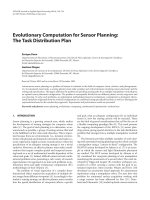
Figure 1: Top view of our matrix transform imager. This architecture and approach allows for arbitrary separable matrix image transforms;
these transforms are programmable because we use floating-gate circuits. Voltage inputs from various basis functions are broadcast along
columns, and output currents are summed along lines on each row. Each pixel processor multiplies the incoming input with the measured
image sensor result, and outputs a current of this result. Basis functions could be from spatial oscillators, pattern generating circuits, or
arrays of stored analog values (i.e., floating-gate storage). We can also compute block image transforms w ith bases having a smaller region of
support, digital control, and smaller block matrices for block image transforms. Finally, we can get multiple parallel results, since all of the
matrix transforms could operate on the same image flow.
The paper is organized into five sections. In Section 2,we
present an overview of floating-gate devices, circuits, and sys-
tems. We also discuss two key systems: floating-gate circuits
for arbitrary parallel waveform generation and floa ting-gate
circuits for matr ix multiplication. In Section 3,wepresent
the basic architecture design (single imager and computa-
tional system) and highlight the aspects of programmability
that will be enabled by using flo ating-gate c ircuits. We also
present an overview of our concept of cooperative analog-
digital signal processing (CADSP) and its relationship to
neuromorphic image processing. In Section 4,wepresent
the basic pixel elements and their characterization as well as
the mathematics needed to predict performance for a given
application based on experimental measurements, includ-
ing estimates on noise, speed, and so forth. In Section 5,we
present system examples and measurements, and we con-
clude in Section 6.
2. ENABLING TECHNOLOGY: FLOATING-GATE
CIRCUITS
From their early beginning, floating-gate devices have held
promise for use in analog signal processing circuits and bio-
logically motivated computation [29, 31, 32, 33]. Since these
beginnings, this technology has begun to fulfill some of the
early expectations; for a good review see [27]. One can imag-
ine many straightforward approaches to using floating-gate
circuits in imagers. For example, one could eliminate circuit
offsets and dark current errors in the pixel circuits as well as
in sensing circuits [11, 30]. These approaches often decrease
the fill factor of the pixel. With the signal processing poten-
tial of floating-gate circuits already shown in auditory appli-
cations, one might imagine the possibility of a wider set of
applications.
Our transform imager and architecture is enabled by
floating-gate circuits in three ways. First, we can store ar-
bitrary analog waveforms enabling arbitrary matrix image
transforms or block image transforms. Second, we can pro-
gram these waveforms to account for average device mis-
match along a column, thereby getting significantly higher
image transform quality. Third, we can use floating-gate cir-
cuits to compute additional vector-matrix computations. As
a result, we can use a single, simple pixel element to perform
a wide range of possible computations.
In the following sections, we will explore the issues of
using floating-gate elements for the transform imager ap-
proaches. In Section 2.1, we present an overview of floating-
gate circuits focusing on imager applications. In Section 2.2,
678 EURASIP Journal on Applied Signal Processing
Input
capacitor
Floating gate
transistor
Floating gate
MOS tunneling
capacitor
Poly2 cap
Metal 1 layer
SiO
2
SiO
2
n-well
p-substrate
n-well
p
+
n
+
V
in
V
fg
(Floating gate)
V
tun
V
s
V
d
Figure 2: Layout, cross-section, and circuit diagram of the floating-
gate pFET in a standard double-poly, n-well MOSIS process. The
cross-section corresponds to the horizontal line slicing through the
layout view. The pFET transistor is the standard pFET transistor
in the n-well process. The gate input capacitively couples to the
floating-gate by either a poly-poly capacitor, a diffused linear ca-
pacitor, or an MOS capacitor, as seen in the circuit diagram (not
explicitly shown in the other two figures). We add floating-gate
charge by electron tunneling, and we remove floating-gate charge by
hot-electron injection. The tunneling junctions used by the single-
transistor synapses are regions of gate oxide between the polysilicon
floating-gate and n-well (an MOS capacitor). Between V
tun
and the
floating-gate is our symbol for a tunneling junction capacitor with
an added arrow designating the charge flow.
we address the issues of programming a large number of
floating-gate elements. In Section 2.3, we discuss the two im-
portant floating-gate c ircuits/systems used in the transform
imager architecture:
(i) generation of arbitrary on-chip waveforms,
(ii) analog vector-matrix multiplication.
One could imagine straightforward applications of the entire
spectrum of floating-gate technologies and signal processing
algorithms applied to this architecture [34].
2.1. Floating-gate circuits for imager applications
Floating-gate devices are not just for digital memories any-
more, but they are used as circuit elements with analog mem-
ory and impor tant time-domain dynamics [27]. We define
floating-gate circuits as the field where flo a ting-gate devices
are used as circuit elements and not simply as digital memory
elements. Floating-gate devices and circuits typically are di-
vided into three major functions: analog memory elements,
part of capacitive-based circuits, and adaptive circuit ele-
ments.
Figure 2 shows the layout, cross-section, and circuit sym-
bol for our floating-gate pFET device. A floating gate is a
polysilicon gate surrounded by silicon-dioxide. Charge on
the floating gate is stored permanently, providing a long-
term memor y, because it is completely surrounded by a high-
quality insulator. From the layout, we see that the floating
gate is a polysilicon layer that has no contacts to other lay-
ers. This floating gate can be the gate of an MOSFET and can
be capacitively connected to other layers. In circuit terms, a
floating gate occurs when we have no DC path to a fixed po-
tential. No DC path implies only capacitive connections to
the floating node, as seen in Figure 2.
The floating-gate voltage, determined by the charge
stored on the floating gate, can modulate a channel between a
source and drain, and therefore, can be used in computation.
Floating-gate circuits provide IC designers with a practical,
capacitor-based technology; since capacitors, rather than re-
sistors, are a natural result of an MOS process. Floating-gate
devices can compute a wide range of static and dynamic
translinear functions by the particular choice of capacitive
couplings into floating-gate devices [35].
We modify the floating-gate charge by applying large
voltages across a silicon-oxide capacitor to tunnel electrons
through the oxide or by adding electrons using hot-electron
injection. The physical effects of hot-elect ron injection and
electron tunnelling become more pronounced as the line
widths of existing processes are further scaled down [36],
improving our floating-gate circuits. Floating-gate circuits
based upon programmable (shor t periods of charge modifi-
cation) and adaptive (continuous charge modification) tech-
niques have found uses in applications from programmable
on-chip biasing voltages and sensor circuits [37], to remov-
ing offsets in differential pairs and mixers [38], and to pro-
grammable filters and adaptive networks [33, 38].
These floating-gate transistors provide nonvolatile stor-
age, compute a product between this stored weight and the
inputs, allow for programming that does not affect the com-
putation, and adapt due to correlations of input signals.
These single transistor learning synapses [29], named be-
cause of the similarities to synapses, lead to a technology
called analog computing arrays. Figure 3 shows a general
block diagram of our floa ting-gate computing array. We have
built analog computing arrays for auditory signal process-
ing [28, 34, 39], as well as for image signal processing. The
memory cells may be accessed individually (for readout or
programming), or they may be used for full parallel com-
putation within the array (as in matrix-vector multiplication
or adaptation). Therefore, we have full parallel computation
with the same circuit complexity and power dissipation as
the digital memory needed to store a 4-bit digital coeffi-
cient. This technology can be integrated in a standard dig-
ital CMOS process or in standard double-poly CMOS pro-
cesses. Furtherm ore, we only need to operate this system with
effectively one memory access per incoming sample, or in
other words, the system only needs to operate at the incom-
ing data speed (maximum input frequency), thereby reduc-
ing requirements on our overall system design.
2.2. Programming arrays for floating-gate elements
Routinely programming thousands to millions of floating-
gate elements requires systematic, automated methods for
High Fill-Factor Imagers for Neuromorphic Processing Enabled by Floating-Gate Circuits 679
V
1
V
2
···
···
···
···
···
···
···
V
n−1
V
n
Signal
decomposition
Post processing computation
(a)
Gate control
voltage
R2
R1
R0
Drain
control
voltage
C0 C1 C2 C3
(b)
Programming board
232 Serial port
PIC
Current
monitor
block
−
+
To dr a i n
SPI
DAC
To g a te
Regulator
Selection logic
Level
shifters
Header
Testing board
DUT
Additional
user
circuits
(c)
×10
−8
1.2
1
0.8
0.6
0.4
0.2
0
Drain current
0 102030405060
Column
(d)
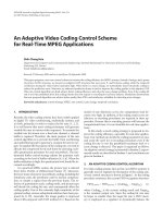
Figure 3: Computation and programming in floating-gate analog computing arrays. (a) Illustration of our computing in floating-gate mem-
ory arrays. A typical system is an array of floating-gate computing elements, surrounded by input circuitry to precondition or decompose
the incoming sensor signals, and surrounded by output circuitry to postprocess the array outputs. We use additional circuitry to individually
program each analog floating-gate element. (b) Floating-gate array demonstrating element isolation by controlling the gate and drain voltage
of each column and row. Selection of gate and drain voltages is controlled by on-chip mux circuitry. (c) Block diagram of our custom pro-
gramming board for automatic programming of large floating-gate arrays. This board, controlled by a PIC microcontroller and interfaced
with a computer through a serial (RS232) port, is capable of programming floating-gate arrays fabricated in a wide range of processes. This
board allows easy integration with a larger testing platform, where programming and computation are both required. The DAC provides
voltages for the gate and drain, as well as dr iving a voltage regulator to set the voltage of the chip to program. Level shifters shift the PIC’s
logic levels to the chip’s logic le vels. Currents are measured on the board as well, the SNR has been experimentally found to be equivalent
to 9-bit accuracy over 2 orders of magnitude in current. (d) A single row of floating-gate multiplier blocks programmed to scaled cosine
coefficients. These blocks are essential to performing analog frequency transform functions. Because the values are arbitrary, one can also
set these to be linear or to increase or decrease logarithmically.
programming. We have developed such a method as a critical
part of this single-chip system. We take a similar approach
as we described elsewhere [27 , 28, 29, 40]. Our program-
ming scheme minimizes interaction between floating-gate
devices in an array during the programming operation. This
scheme also measures results at the circuit’s operating condi-
tion for optimal tuning of the operating circuit (no compen-
sation circuitry needed). Once programmed, the floating-
gate devices retain their channel current in a nonvolatile
manner.
Figure 3b shows that it is possible to isolate individual
elements (access to an individual gate and drain line) in a
large matrix using peripheral control circuitry. We program
a device by increasing the output current using hot-electron
injection, and erase a device by decreasing the output cur-
rent using electron tunnelling. Because of the poorer selec-
tivity, we use tunnelling primarily for erasing and for rough
programming steps. Our programming scheme performs in-
jection over a fixed time window using drain-to-source volt-
age based on the actual and target currents. The time used
680 EURASIP Journal on Applied Signal Processing
for injection was 10milliseconds. We have successfully used
100microseconds, and we see no technological limitation to
using one microsecond as injection time. These fast values
are critical to programming mass production or large arrays
of floating gates.
Programming a floating-g ate element involves being able
to adjust multiple control voltages for a single element. The
isolation circuitry is made of multiplexors that switch the
drain and gate voltages of the desired element onto a com-
mon bus for each signal. Other elements are switched to
a separate voltage to ensure that those devices will not in-
ject. Any circuit containing progra mmable floating-gate el-
ements must also have various switching circuitry to access
each floating-gate e lement in a standard array.
We designed a custom programming board to program
large floating-gate arrays. The board, shown in Figure 3,al-
lows for flexible floating-gate array programming over a wide
range of IC processes and allows for nearly transparent op-
eration to the user. Using custom circuits to program the
floating gates allows for a self-contained programmer at a
lower cost than a rack of testing equipment. This program-
ming board is connected to the chip via a standard header
that allows the option of additional logic when used as part
of a larger testing approach. Figure 3 shows the output from a
row of floating-gate multipliers that have b een programmed
to perform a differential cosine scale multiplication on the
input signals.
2.3. Transform imager floating-gate systems
The transform imager architecture requires using fundamen-
tal floating-gate circuits/systems for the generation of arbi-
trary on-chip waveforms and for analog matrix-vector multi-
plication. Other floating-gate circuits are used to further en-
hance the circuit and signal processing performance of these
systems.
Floating-gate basis generator
We use floating-gate circuit elements to store and to gen-
erate the arbitr ary basis functions needed for the matrix-
vector multiplication on the imager. This approach com-
putes a similar function to ISD’s audio recording ICs
[41], but uses flo a ting-gate circuits in a standard pro-
cess rather than analog EEPROM cells in a special pro-
cess. Figure 4 shows the top-level view of our basis gen-
eration circuitry. This system operates in both operation
(basis generation) mode and programming mode. In op-
eration mode, we have an array of stored values that are
output in sequence. Lowpass filtering on the output re-
sults in a continuous-time analog signal. In programming
mode, we can easily reconfigure this circuitry on the out-
side edges for programming, resulting in very high circuit
density. This approach is compatible with our standard pro-
gramming structure and algorithm. In operation mode, the
digital logic is a shift register or a counter behind the de-
coder, while, in programming mode, the digital logic is a de-
coder.
V
d-prog
V
dd
Drain mux
V
d1
V
d2
V
d3
V
d4
V
dm
Prog
Gate logic and mux
V
g1
V
g2
V
g3
V
gn
.
.
.
.
.
.
.
.
.
.
.
.
···
···
···
···
Prog
I-VI-VI-VI-VI-V
To gate lines of imager cells
n-well p-sub n-well
Drain
p
+
Floating gate (p1)
Gate
n
+
Floating gate (p1)
V
d
V
dd
(source)
V
g
V
tun
Figure 4: Top-level view of our basis generation circuitry. In opera-
tion (run) mode, we have an array of stored values that are output in
sequence. Lowpass filtering on the output results in a continuous-
time analog result. In programming mode, we can easily reconfig-
ure this circuitry on the outside edges for programming. As a re-
sult, we achieve very high circuit density. In operation mode, the
digital logic is a shift register or a counter behind the decoder; In
programming mode, the digital logic is a decoder to conform to
current standards. The capacitors can be either double-poly capaci-
tors or MOS capacitors (single-poly process); both approaches work
equally well. In single-poly, the coupling capacitor is built using an
MOS capacitor.
Floating-gate vector-matrix multiplication
We use the floating-gate circuit elements to compute ana-
log multiplications of a signal vector with a stored, pro-
grammable matrix. We can perform vector matrix computa-
tions using our existing analog computing array (ACA) tech-
nology based upon flo ating-gate circuits [28]. Using the out-
put image stream, this system will compute a transposed ma-
trix transform.
This system operates both in operation (basis generation)
mode and programming mode. In operation mode, we have
an array of four-quadrant multipliers with stored values at
each multiplier. The inputs can be either currents or volt-
ages depending upon the particular system interfacing and
linearity requirements. For current inputs, the circuit is a set
of programmable-gain current mirrors, resulting in minimal
High Fill-Factor Imagers for Neuromorphic Processing Enabled by Floating-Gate Circuits 681
distortion. We also use current inputs, because the outputs
from previous stages are usually currents. Temperature de-
pendence is based upon the difference in floating-gate charge
[32]. The programmed currents remain within 10 percent for
a factor of four range of currents over 0–40
◦
C, and change in
similar directions throughout the array (gains will scale).
3. TRANSFORM IMAGER SYSTEM
3.1. Cooperative analog-digital signal
processing framework
Neither analog signal processing nor digital signal process-
ing can exist in current technologies without the other; that
is, real-world signals are analog while much of the modern
control and communication is digital. Typically, one does
not think of analog and programmability together—analog
circuits are primarily for preamplifiers, and programmabil-
ity has been exclusively in the domain of digital processing.
However, new advances in analog VLSI circuits have made it
possible to perform operations that more closely reflect those
done in DSP applications. Furthermore, analog circuits and
systems can be programmable, reconfigurable, adaptive, and
at a density comparable to digital memories [27, 28, 29, 42].
We define CADSP as looking at the issues of using com-
binations of programmable analog signal processing and dig-
ital signal processing techniques for real-world processing
[43]. Our goal in CADSP is to build systems that benefit
from the advantages of both types of signal processing to
make something better than the sum of its parts and to en-
hance the overall functionality of a system by utilizing ana-
log/digital computations in mutually beneficial way. There-
fore, one might wonder if we have both digital and analog
signal processing available, how does one choose a particu-
lar solution for a given application. The question of where to
partition the analog-digital boundary is still an open research
question.
3.2. Transform imager system overview
Figure 1 shows the block diagram of our transform imager
technology. This approach allows for retina and higher-level
bioinspired computation in a programmable architecture
that still possesses similar high fill-factor pixels of APS im-
agers. If the incoming voltages represent functions in time,
particularly transform bases like sine and cosine, then we are
performing computations analogous to matrix image trans-
forms. The output is a continuous stream of each row of the
transformed image, repeated at a desired frame rate. This ap-
proach is enabled by floating-gate circuits in storing arbitrary
analog waveforms for image transforms, in programming
waveforms to account for average device mismatch, and in
performing additional matrix-vector computations.
This transform imager can compute arbitrary separable
2D linear operations. These operations are expressed as two
matrix multiplications on the image
Y
= A
T
PB, (1)
where P is the image array of pixels, Y is the computed out-
put image array, and A and B are the transform matri ces
corresponding, respectively, to the transform on the image
plane by the basis functions and the transform matrix cor-
responding to the floating-gate-enabled transform after the
image plane. The values of A and B are stored in an analog
floating-gate array typically on the imager IC and applied to
the pixel columns. Furthermore, if the input waveforms are
continuous, then the result is a continuous waveform, result-
ing in added computational options. For example, the choice
of output signal sampling will result in different discrete-
time inspired computations with an identical setup.
3.3. Application of the transform imagers
The transform imager architecture is both modular and pro-
grammable making it ideal for image dataflow computations.
This architecture’s scalability makes it feasible to compute
image oper ations at large-scale resolutions comparable to
those in digital cameras. Furthermore, the image processing
architecture computes on the image plane, thus allowing for
data reduction that is compatible with machine vision and
biological modeling. The image sensor can be used to sub-
sample the incoming data if desired, or if the resulting sys-
tem can handle the data rate, the full image can be passed on
so that easier refinement can occur farther up the processing
chain. The additional processing may be in analog circuitry
or a digital system.
This architecture is modular because the output dataflow
is a sequence of columns from an image. This image is either
from a set of sensors or the output of some signal processing.
We can have multiple image processing steps, where each in-
termediate result can be acquired by the controlling digital
system for higher levels of processing. Furthermore, the out-
puts are continuous waveforms, allowing time-domain filters
to be used to obtain spatial responses and image interpola-
tion.
One must also consider the interface between computa-
tional blocks. A 1024
×1024 imager computing at a 60 Hz im-
age rate requires a parallel data rate (1024 sig nals) of 60 kHz.
If two blocks are adjacent on the same IC, then this data r ate
is trivial to accommodate. However, if these signals are being
passed between chips over 100 mega analog samples per sec-
ond are required, which is a more challenging specification.
This rate is similar to reading out pixels from any standard
CMOS array. Each pixel could be directly read out in a trans-
form imager, since a column scan is equivalent to multiplica-
tion by a digital value moving by one position for each step.
In general, this issue is significant wh en interfacing to a dig-
ital system, since multiple “images” could be transmitted to
the controlling digital system.
Separable matrix image transforms
Separable systems play an important part in image process-
ing because of their simplified design and implementation.
A 2D system is said to be separable if it (i.e., the impulse re-
sponse) can be expressed as a product of two functions of one
682 EURASIP Journal on Applied Signal Processing
variable each:
h
n
1
,n
2
= h
1
n
1
h
2
n
2
. (2)
A separable system can operate on the columns and rows of
an image independently. As a result, a separable system can
be written as a pair of matrix operations as in (1). The left-
hand side matrix A
T
operates on the columns of the image P
and the right-hand side matrix B operates on the rows of the
image.
In image processing, the most common linear operations
consist of FIR filtering and real transforms such as the dis-
crete cosine transform (DCT) or wavelet transforms. Exam-
ples of the left-hand side matrices, A
T
, for these operations
are shown in Figure 5.
The range of operations possible within the architecture
andexpressedin(1) is significant. For example, it is possi-
ble to use differentiating FIR filters to do better edge detec-
tion or lapped orthogonal transforms for image compression
without blocking artifacts. Smoothing filters combined with
a decimation scheme could provide simple data reduction.
Arbitrary transforms can be considered, because computa-
tional complexity and efficient algorithms are not a concern.
Additionally, cascaded operations can be performed by col-
lapsing the matrices describing the multiple operations:
Y = C
T
A
T
PB
D =
ˆ
A
T
P
ˆ
B, (3)
where
ˆ
A = AC and
ˆ
B = BD.
Note that even though arbitrary matrices can be used
without considering traditional computational complexity,
the connectivity complexity should be considered. For ex-
ample, a full image transform requires the instantiation and
routing of the full transform matrices while a block trans-
form can be implemented using only enough elements and
interconnects for the nonzero transform matrix elements.
Temporal filtering
One interesting question with this flow model is how to per-
form temporal filtering. We can either build the filters di-
rectly into the pixel, which would result in much larger pix-
els and greatly increase the system cost for a given resolu-
tion, or we can store a delayed version of the transformed
image. This approach requires a temporary storage array for
currents or voltages for each delay thus limiting the number
of temporal delays that can be built in practice (Figure 6).
Our approach is to build a set of current mode sample-and-
hold elements into an array that can be used for tempo-
ral filters. Dynamic current sources can be built that store
their currents at reasonable accuracy for seconds, particu-
larly with on-chip compensation of leakage through MOS-
FET switches.
Applications of temporal filtering include subtraction of
constant backg round images, temporal differencing, motion
estimation, and, by using an array of floating-gate elements
instead of the sample-and-hold elements, fixed images such
as offseterrorsfromdarkcurrentsmaybesubtractedout.In
general, however, temporal filters should be u sed sparingly
or after spatial compression due to the number of required
sample-and-hold elements.
One could imagine combining these temporal filters as
well as the spatial filters of the transform imager approach to
be a front-end processor to compute optical flow.
3.4. Comparison of transform imagers
with existing technologies
Focal-plane processing is characterized by significant
amounts of signal processing occurring at the image plane,
but usually at the cost of a small fill factor. Early retina model
systems used focal-plane processing to mimic the edge
enhancement properties in the early retina processing based
on photodiodes and phototransistors that naturally occur in
a silicon CMOS process [12, 13, 14]. Later designs improved
so as to be usable in systems at high density levels [14, 15, 16]
and for high performance [44]. From these retina chips, sev-
eral higher level processing ICs have been built to investigate
stereo processing [17, 18], communication architectures for
action potentials [19], attention computations, and motion
[20, 21, 22, 23, 24, 25, 26]. Typically, because of the large
pixel size associated with the large number of transistors in
each pixel, image sensors w ith retinal computation typically
only have a fairly small number of pixels on a given IC.
In only a very few cases, one will see more than 50, 000
image elements on a fairly large IC [14]. Therefore, retinal
processing imagers and research are focused primarily on
machine vision tasks where the required pixel count can
be smaller; for example, flies accomplish amazing things
with the resolution from a small number of pixels [25, 26].
Although much can be explored in vision problems at the
level of flies, many neuromorphic visual signal processing
systems aim toward modeling much larger organisms.
APS imagers took a related route to the silicon retina
models. These approaches, typically credited to Fossum, et
al., [1, 2, 3, 4, 5, 6, 7, 8, 9, 11, 45] worked with photodiode-
based arrays w ith minimal circuitry in the pixel, resulting
in large imaging arrays, and therefore, a technology viable
for digital cameras and more sophisticated computations. To
characterize the spatial efficiency of a pixel, the concept of
fill factor, which equals the ratio of image sensor area over
the pixel area, is defined. The larger fill factor implies b etter
spatial resolution per unit area. Typical APS imagers have fill
factors from 30–50%, while typical focal-plane imagers have
fill factors around 1–4%.
The question is whether one can combine the high fill
factor advantages of APS imagers with the computational ca-
pabilities of retinal processing imagers. A few approaches tr y
to bridge this gap [7, 8, 10, 19, 46, 47, 48],buttheyonlybegin
to unlock the potential of these approaches. For example, the
introduction of floating-gate circuits can enhance the per for-
mance of imager elements, but often straightforward appli-
cation of these circuits results in larger pixels, and therefore,
a decreased fill factor. Fur thermore, these retina approaches
have not been elegantly merged into a single circuit architec-
ture; therefore, even in the desig n of retina ICs, several hard
trade-offs remain.
High Fill-Factor Imagers for Neuromorphic Processing Enabled by Floating-Gate Circuits 683
h
0,0
h
0,1
h
0,2
h
0,3
h
0,4
h
0,5
h
0,6
h
0,7
h
1,0
h
1,1
h
1,2
h
1,3
h
1,4
h
1,5
h
1,6
h
1,7
h
2,0
h
2,1
h
2,2
h
2,3
h
2,4
h
2,5
h
2,6
h
2,7
h
3,0
h
3,1
h
3,2
h
3,3
h
3,4
h
3,5
h
3,6
h
3,7
h
4,0
h
4,1
h
4,2
h
4,3
h
4,4
h
4,5
h
4,6
h
4,7
h
5,0
h
5,1
h
5,2
h
5,3
h
5,4
h
5,5
h
5,6
h
5,7
h
6,0
h
6,1
h
6,2
h
6,3
h
6,4
h
6,5
h
6,6
h
6,7
h
7,0
h
7,1
h
7,2
h
7,3
h
7,4
h
7,5
h
7,6
h
7,7
(a)
h
0,0
h
0,1
h
0,2
h
0,3
0000
h
1,0
h
1,1
h
1,2
h
1,3
0000
h
2,0
h
2,1
h
2,2
h
2,3
0000
h
3,0
h
3,1
h
3,2
h
3,3
0000
0000h
0,0
h
0,1
h
0,2
h
0,3
0000h
1,0
h
1,1
h
1,2
h
1,3
0000h
2,0
h
2,1
h
2,2
h
2,3
0000h
3,0
h
3,1
h
3,2
h
3,3
(b)
h
0
h
1
000000
h
−1
h
0
h
1
00000
0 h
−1
h
0
h
1
0000
00h
−1
h
0
h
1
000
000h
−1
h
0
h
1
00
0000h
−1
h
0
h
1
0
00000h
−1
h
0
h
1
000000h
−1
h
0
(c)
h
0,0
h
0,1
h
0,2
h
0,3
h
0,4
h
0,5
h
0,6
h
0,7
h
1,0
h
1,1
h
1,2
h
1,3
h
1,4
h
1,5
h
1,6
h
1,7
h
2,0
h
2,1
h
2,2
h
2,3
0000
0000h
2,0
h
2,1
h
2,2
h
2,3
h
3,0
h
3,1
000000
00h
3,0
h
3,1
0000
0000h
3,0
h
3,1
00
000000h
3,0
h
3,1
(d)
Figure 5: Image transform matrix examples. The transform imager can perform many types of operations of the type Y = A
T
PB,whereA
T
operates on the columns of the image P and B operates on the rows. Examples of A
T
are shown here for different types of operations. (a) A
transform of the entire image where h
i,j
represent the windowed transform basis elements. (b) Block transform of the type more likely to be
used in image compression. (c) FIR filter applied to the image, note that the corner coefficients are denoted with
’s because they are often
normalized to account for the shorter length of the filter at that point; or they may be changed to accomplish filtering of a symmetrically
extended image with h
0
= h
0
and h
1
= 2h
1
, and so forth. (d) Wavelet transfor m of the image, note that a block wavelet transform could be
also applied.
Transform
imager
Image
storage
Corrected
output
Figure 6: Imager architecture for taking image differences; we need
a separate array to store one frame. An array of floating-gate de-
vices (similar to the basis generation array) would implement image
storage for eliminating nearly constant images such as o ffset errors
from dark currents, or constant background images. Currents can
be scaled, and typically the current from a transform imager will
be scaled as well; therefore, removing dark currents, which are typ-
ically in fA range, would be subtracted with a current in the high
pA range. An array of sample-and-hold elements would implement
image storage for temporal filtering and temporal derivatives asso-
ciated with motion. This technique can be generalized for a wide
range of temporal filters; the number of temporal delays propor-
tionally increases the image storage. The advantage of subtracting
a fixed image is that we get higher system density, since we do not
need to integrate the two core cells into a single element with the
supporting control logic. Also, any floating-gate elements are re-
moved from potential UV light, therefore reducing any floating-gate
charge drift issues.
Transform imagers borrow from both focal-plane im-
agers like retinas as well as standard APS and random-access
imagers to create this unique architecture. Our transform
imager cell perfor ms computation at the pixel plane, but stil l
holds to a fill factor greater than 40%. It also allows for retinal
and advanced biological-type processing in a programmable
architecture while preserving the overall high fill factor of
APS imagers. Therefore, we have the best of both worlds in a
single architecture. Furthermore, this approach should unify
the advantages of both retina approaches in a single struc-
ture.
4. BASIC TRANSFORM IMAGER PIXEL ELEMENT(S)
This section describes the first block of this architecture, the
basic transform imager. We discuss the basic processor struc-
ture of the computation (multiplication) of the sensor signal
in each pixel. This approach could include more advanced
image sensor elements/circuits with a corresponding modi-
fication to the resulting fill fac tor. We present experimental
data from an instrumented 14
× 14 image block, requiring
roughly 150 × 200 µm for the array in a 0.5 µmCMOSpro-
cess. We present results from a signal pixel, the resulting com-
putation, and effect of mismatch and offsets throughout this
circuit.
These experimental results become the starting point to
build large pixel arrays with the resulting floating-gate c ir-
cuits. As a result, we need to have an analytic foundation for
scaling these systems and for estimating system performance.
The goal for the analytical discussions of these circuits is 1-
million pixel arrays, which we configure as a 1024 × 1024
array of pixels, that operate at 60 frames a second. We have
already built arrays up to 512 × 512 in size, and have plans to
reach the 1024 × 1024 size in the near future.
684 EURASIP Journal on Applied Signal Processing
I
1
V
1
I
2
V
2
(a)
V
1
V
2
C
1
C
2
V
tun
V
fg
V
dd
I
out
(b)
Figure 7: Key circuit elements for the transform imager technology.
(a) Pixel element. To multiply the transduced photodiode current
by incoming basis functions, we use a differential pair to modulate
a fraction of the sensor current through the transistors. For suffi-
ciently small differential input voltages, we get a linear multiplica-
tion, as illustrated in the resulting experimental data. The simplicity
of the pixel circuit results in fill factors competitive with APS im-
agers. (b) Floating-gate transistor. This circuit can store a current
based upon the charge at the floating-gate node. Therefore, we use
this element to store the basis functions for the transform imagers.
This circuit can also be used as a transistor, and w hen operating with
subthreshold currents, this transistor computes a product of the in-
put voltage with the stored current. Therefore, we use this element
in the matrix-vector multiplication memory arrays.
4.1. Basic pixel element
Each pixel is composed of a photodiode sensor element and
an analog multiplier. Figure 7a shows that the circuit element
for this multiplication is an nFET differential pair. For the
differential pair operating with subthreshold bias currents
(which should always be the case due to the low-level im-
age sensor currents), we can express the differential output
current as [12]
I
1
− I
2
= I
sensor
tanh
κ
V
1
− V
2
U
T
, (4)
where κ is the gate coupling efficiency into the transistor sur-
face potential (typically 0.6–0.8), and U
T
is kT/q.IfV
1
− V
2
inputs are such that the circuit is in its linear range, then
×10
−10
3
2
1
0
−1
−2
−3
Differential output current (A)
−0.5 −0.4 −0.3 −0.2 −0.100.10.20.30.40.5
Differential input voltage (V)
Figure 8: Differential output current versus differential input volt-
age for three different uniform light illuminations. The second level
is a factor of 1.8 brighter than the first level, and the third level is a
factor of 2.5 brighter than the first level. We obtain a multiplication
of the sensor current with the differential input voltage in the linear
range of this differential pair. Furthermore, we can easily read the
photosensor current by applying a large differential input voltage
for the column of interest.
we get
I
1
− I
2
= I
sensor
κ
V
1
− V
2
U
T
(5)
or the product of the sensor output and the differential input
voltage.
The experimental data in Figure 8 shows that we get a
linear multiplication w ithin the linear range, as expected. A
single pixel would result in 300-pA current levels from typ-
ical room fluorescent lights at roughly 2 m from the imager
without a lens to focus the light. A single pixel could include
more advanced image sensor elements/circuits with a corre-
sponding modification to the resulting fill factor. Addition-
ally, each pixel could be directly read out by this technique,
since a column scan is equivalent to multiplication by a dig-
ital value moving by one position for each step (tanh(x)1or
−1 for large x magnitudes).
Offsets in differential pairs are important for most analog
design problems and a re not exception for this imager. Small
input offsetvoltagesresultprimarilyinaDCoutputcurrent
and have a small effect on the resulting algorithm. Because
each pixel value is modulated by the incoming basis wave-
form, we have no signal at DC, and therefore, we filter out
the DC signal. On the other hand, large input offset voltages
result in no output signal, since one transistor of the differ-
ential pair pulls all of the sensor current. Pixels with these
large offsets will result in significant image distortion at these
points. Figure 9 shows the measured input voltage offsets for
High Fill-Factor Imagers for Neuromorphic Processing Enabled by Floating-Gate Circuits 685
14
12
10
8
6
4
2
y-position
2 4 6 8 10 12 14
x-position
Figure 9: Voltage offsets measured from our 14 × 14 arr ay. We
shined a uniform light pattern on this chip and measured the result-
ing differential currents to determine the input voltage offset. The
largest value (light color) was
−90 mV, and the smallest value (dar k
color) was 10 mV. One column had significant offsets, but this col-
umn is still usable, since we could program the basis function along
that column to have an equivalent average offset. The average off-
set for column 8 was
−62.7 mV, the other elements had an average
offset of 1.4 mV with a standard deviation of 3.4 mV. The standard
deviation from the column averages was 6.92 mV; therefore, all de-
vices would start in their linear range for zero input voltage resulting
in minimal distortion.
our pixel array. We found that most of the offsets were within
10 mV of the other elements along the column. We can ac-
count for average column offsets by appropriately program-
ming the input basis functions. These offsets can be further
reduced by improving the matching of the two devices. We
used(W/L)of1.8µm/1.8 µm in a noncommon centroid lay-
out geometry. With a slight reduction in fill factor, the mis-
match could be significantly reduced. In applications where
very high performance (and therefore nearly zero offsets)
is required, one can use floating-gate tuning techniques for
pixel elements [11]ordifferential pairs [38], with the accom-
panying decrease in fill factor.
Our measurements show that a single pixel element ex-
hibits little change from DC to 100 Hz for typical fluorescent
lights. This frequency response will be dependent upon the
incoming light levels. We observe a corner frequency at 30 Hz
for four orders of magnitude of light intensity lower than av-
erage room light. From these measurements, we expect suf-
ficient bandwidth for a 1024 × 1024 imager performing full-
matrix operations at a 60 Hz image rate.
4.2. Modeling computation errors in transform imager
computations
In practice, the elements will not be perfect multipliers and
will not be exactly identical to the other elements. If we as-
sume that one linearly encodes the broadcast gate voltages
as the sensor modulation signal (by programming), then the
errors encountered in this architecture can be divided into
three categories.
(1)
Gain error—primarily due to
κ
mismatch in the differ-
ential pair transistors.
Typically κ matches fairly well
for transistors with similar currents and for source
voltages at similar voltages.
(2)
Offset error—primarily due to offsets in the differen-
tial pair tr ansistors.
As long as the modulation signal is
roughly within the linear range of the differential am-
plifier, we can eliminate offsets by eliminating the low
frequency signal (less than the frame r ate) from the re-
sult, because there is no signal at these low frequencies
(we are modulating the pixels) except for the effect of
offsets.
(3)
Harmonic distortion—primarily due to harmonic dis-
tortion in the differential pair transistors:
Harmonic
distortion effectively results in spreading modulation
energy to other pixels. This spreading is independent
of the sensor signals since the modulation signal stays
at the same amplitude. We show below that one can
modify the modulation signals to account for this
spreading such that the transform is effectively free of
this signal spreading.
We focus on multiplication errors because addition of
currents by KCL is an ideal computation. Another source of
error comes from the dark currents, which are typically in
the fA range and therefore, are important for pixels operat-
ing in low-light levels. We can use floating-gate elements to
eliminate them, as shown in Figure 6.
One can modify the modulation signals to account for
this spreading such that the transform is effectively free of
this signal spreading. To analyze this problem, we decompose
all modulated signals, x(t), into a finite Fourier series because
the signals repeat for each frame, and the signals have a max-
imum frequency by the clock rate of the basis generator. We
write the Fourier series as
x
k
(t) =
N
=−N
a
k
e
jw
frame
, (6)
where a
kl
is the th coefficient for the kth signal, and w
frame
is 2π times the frequency of the frame rate. Note that a
k0
= 0
because there is no DC signal component. In matrix form,
x(t) = Af(t)where f
(t) = e
jw
frame
. The output from the
imager is
y = Px = PAf (t), (7)
where P is the matrix of sensor values. If the multiplication
distorts the computation (i.e., from the differential transis-
tor pairs), we can reformulate the result of second, third, and
higher-order harmonics by modifying A by A
1
, which takes
these terms into account. Furthermore, we can invert this
process to modify the start ing matrix A to get a matrix A
1
,
which gives the desired transform of interest. The correction
will depend on the desired transform.
686 EURASIP Journal on Applied Signal Processing
4.3. Bandwidth of the transform imager
Since we are modulating the input pixel currents, one should
consider the highest modulation frequency that a particular
pixel can support. We define the bandwidth as the highest
frequency (i.e, the fastest generated signal) minus the low-
est frequency (i.e, the frame rate or block rate); typically
assuming that the bandwidth as related to the highest fre-
quency is sufficient. This maximum frequency/bandwidth
defines a trade-off between the resulting frame rate and the
number of available pixel elements. We are looking at the fre-
quency response for a differential signal, therefore, the source
node of the differential pair is nearly fixed. Sensor capaci-
tance and any capacitance in parallel with the phototrans-
duction sensor have negligible effect on the frequency re-
sponse.
For example, for a 1-million pixel imager (1k × 1k-pixel
array), we need 60 kHz modulation for a 60 Hz frame rate.
If the current output lines use one-stage ac tive feedback (as
used in the adaptive photoreceptor [44]) to reduce capacitive
effects, then we could approach these frequencies for 10 pA of
sensor cur rent. A limit of 10 pA significantly limits the range
of input illumination, for lower currents either the image size
must decrease or the frame rate must slow down accordingly.
We can reduce this minimum current level by using
stronger ac tive feedback or by changing the phototransduc-
tion method in the pixel cell. Stronger a ctive feedback will
improve the frequency response at a given current, and there-
fore reduce the minimum current that can be modulated.
The stronger, active feedback requires more gain, and there-
fore more power consumed and increased stability issues.
One can change the phototransduction element to a verti-
cal BJT to amplify the current, but this approach results in a
more than proportional increase in the element noise, as well
as decreases in pixel-circuit fill factor. Experimental measure-
ments have qualitatively verified these results.
Often, early levels of image processing are based upon
block transforms rather than f ull image transforms, and the
bandwidth behaves similarly. For block processing, we often
turn on a basis block when being used, and turn it off when
not being used. The frequency response of turning on or
turning off a block is fairly quick for both operations. Turn-
ing on the block, which means we are bringing up the result-
ing output voltage, looks like a source follower, using nFETs
on the upswing. That is, we are working on the fast transition
region of this circuit. Turning off the block, which means we
are pulling down the resulting output voltage, looks like we
quickly drop the gate voltage below the source voltage, and
therefore, the current through the differential pair FETs is
very small.
4.4. Signal-to-noise issues in transform imagers
Since we are using fairly low subthreshold currents, thermal
noise contributes to most of the transistor noise. Thermal
noise is modeled as [49]
ˆ
I
2
I
2
=
2q
I
∆ f, (8)
where I is the current level. The bandwidth (∆ f ) is approx-
imately the highest frequency (i.e., the fastest generated sig-
nal) of the basis generator. For the 1-million pixel example in
Section 4.3, ∆ f
= 60 kHz, resulting in a relative noise level of
0.14 for a 1 pA bias current through a single transistor.
Due to the low currents (subthreshold), 1/f noise only
becomes noticeable at low frequencies (e.g., 10 Hz). Further-
more, noise generated at frequencies less than the frame rate
will be eliminated from the final computation, so the low 1/f
noise will not affect these circuits. This property is similar to
the computation in correlated double-sampling techniques.
Therefore, we only need to address thermal noise generated
from the sensor circuits.
The noise comes from two sources. First, we get one dif-
ferential pair worth of noise due to the differential pair tran-
sistors on the photodiode. Second, we get two differential
pairs worth of noise at the sensor’s bias current due to the
basis generation structures. For very small signals, the sys-
tem looks like a current mirror for small signals w ith differ-
ent transconductances (the gain = g
m2
/g
m1
), resulting in two
differential pairs worth of noise (two because of no common-
mode rejection for this circuit component). Since each noise
source is independent of the other noise sources, the noise
power of each source increases linearly with the number of
sources (N). Therefore, the noise relative to the signal from a
single pixel is
ˆ
I
2
I
2
=
2qN
I
∆ f (9)
for the 1-mil lion pixel example above, the relative noise level
for the entire pixel sensor is 6.73 (−16.6dB) for a 1pAbias
current in a single sensor and 0.673 (3.43 dB) for 100 pA bias
current. For a completely correlated feature, which means all
1-k elements contribute to a large output signal, we get a
relative noise level of 0.0066 (43.6 dB) for 1-pA bias current
level. Therefore, for this imager setup, either higher illumina-
tion or more coherent features (features selected by the basis
generator) result in increased higher SNR. This SNR value
is better than the SNR if we acquired each pixel at the 60 Hz
frame rate; therefore, correlated features have the higher SNR
as reading the pixel array, but uncorrelated pixels will have
lower SNR.
5. IMAGER SYSTEM RESULTS
We will discuss the overall computation using a 14 × 14-pixel
array in the context of DST and DCT transforms. The re-
sults can be extended to arbitrary matrix transforms. For this
paper, we will concentrate on computing a DST/DCT-like
transforms of the image as a representative of possible matrix
computations. To characterize this imager, we will compute
these transforms for uniform illumination. The ideal DST
would be all zeros, and the ideal DCT would be an impulse
at position (1, 1).
We present experimental data from a small 14 × 14 im-
age block, requiring roughly 150 × 200 µm for the array
in a 0.5 µm CMOS process. Figure 10 shows the results of
High Fill-Factor Imagers for Neuromorphic Processing Enabled by Floating-Gate Circuits 687
14
12
10
8
6
4
2
1357
1/2oftransformed
image
DCT
DST
14
12
10
8
6
4
2
246 8101214
Transpose matrix
operation: DCT
14
12
10
8
6
4
2
246 8101214
Transpose matrix
operation: DST (×10 scaling)
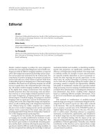
Figure 10: Experimental data from a 14 × 14 test imager. We present one half of the output image after transforming the image (uniform
illumination) using sine waves. The output image is symmetric; therefore, we have output only the first half. Sampled at integer points. DCT
transform: result of an additional cosine transform on initial sine-transformed imager data. We nearly get the ideal impulse function at (0, 0)
position, as predicted by taking a 2D cosine transform of an image of uniform illumination. DST transform: result of an additional sine
transform on initial sine-transformed imager data. The plot of this sine transform multiplied by a factor of 10 in comparison with the cosine
transform; without the scaling factor (×10), the image would look nearly white. We nearly get a zero matrix as we would expect for an input
image of uniform illumination.
(a) (b)
Figure 11: A representative image (output current) experimentally
measured from one of our 128 × 128 transform imagers. We pro-
jected, through a spatial light modulator, multiple X elements across
the screen; Projected image was brighter towards the center; there-
fore we have higher output values and higher SNR towards the cen-
ter. The image quality should be further improved by closer pro-
gramming of our floating-gate elements, moving the current mea-
surement setup on-chip, as well as reducing errors from the mea-
surement setup. (a) An output image for a basis function to read
out the projected image. (b) An output image for a 3
× 3spatial
averaging kernel.
DST/DCT-type transforms on a uniformly illuminated im-
age. We input sine waves of integer frequencies and obtained
the first image result by sampling at π/2 phase of the primary
harmonic. This transform is symmetric, so we show only the
first half of the output waveform. From the resulting wave-
forms (not sampled waveforms), we computed the second
matrix transform using DST coefficients and then for DCT
coefficients. We see some distortion in the transformed im-
ages, which correlates well to harmonic distortion from the
differential pairs. Since the input patterns are fixed, the effect
of harmonic distortion is fixed and appears as an additional
spatial (smoothing) filter. In practice, we can account for this
additional linear spatial filter by modifying the matrix trans-
form coefficients to account for it. In the same process, we
can scale to a 128 × 128 imager with matrix processing for
16 × 16blocktransformsinanareaof4mm
2
.
We have built several functional imagers in 0.5 µmCMOS
technology of sizes 16 × 16, 48 × 48, and 128 × 128. The
128 × 128-size imager uses a block transform window of six-
teen, therefore requires an array of 252 × 16 floating gates, to
store the required basis functions. All of these systems con-
tain the necessary control circuits that allow for program-
ming of individual floating gates. We program the floating-
gate elements to arbitrary values using an external program-
ming board that only requires an external power supply and
standard RS-232 computer interface. We describe this board
elsewhere [28]. We test our imagers by projecting a directed
light source on our imager through a complex lens system.
During our experiments, we have seen little noticeable move-
ment of the floating-gate elements from their respective pro-
grammed values. Figure 11 shows an output image from one
of our 128 × 128 transform imagers.
6. CONCLUSION
We introduced our transform imager technology and archi-
tecture. Transform imagers borrow both from focal-plane
imagers like retinas as well as standard APS and random-
access imagers to create this unique architecture. Our trans-
form imager cell performs computation at the pixel plane,
has a fill factor greater than 40%, and al lows for retinal and
advanced biological-type processing in a programmable ar-
chitecture. Therefore, we have the best of both worlds in a
single architecture.
Our new imaging architecture is enabled by pro-
grammable floating-gate circuits built in standard CMOS
(single or double-poly) processes. The floating-gate circuits
allow for arbitrary pattern generation as well as analog
matrix-vector multiplication of images. This imager is capa-
ble of programmable matrix operations on the image, where
we can represent the image as either a full matrix or using
688 EURASIP Journal on Applied Signal Processing
block matrix operations. The resulting dataflow architecture
directly allows computation of spatial transfor m s, motion
computations, and stereo computations, in a st raightforward
on-chip or multi-chip architecture.
Each pixel is composed of a photodiode sensor element
and a multiplier. We have presented experimental data from
several transform imagers (14 × 14, 16 × 16, and 128 × 128
arrays) showing the performance of the pixel, mismatch be-
tween pixels, and basic transform results. We are currently
in the process of further testing this imager architecture for
various applications.
REFERENCES
[1] O. Yadid-Pecht, R. Ginosar, and Y. S. Diamand, “A random
access photodiode array for intelligent image capture,” IEEE
Transactions on Electron Devices, vol. 38, no. 8, pp. 1772–1780,
1991.
[2] M. Kyomasu, “A new MOS imager using photodiode as cur-
rent source,” IEEE Journal of Solid-State Circuits, vol. 26, no.
8, pp. 1116–1122, 1991.
[3] E. R. Fossum, “CMOS image sensors: electronic camera-on-
a-chip,” IEEE Transactions on Electron Devices, vol. 44, no. 10,
pp. 1689–1698, 1997.
[4] O. Yadid-Pecht and E. R. Fossum, “Wide intrascene dynamic
range CMOS APS using dual sampling,” IEEE Transactions on
Electron Devices, vol. 44, no. 10, pp. 1721–1723, 1997.
[5] E. R. Fossum, “Digital camera system on a chip,” IEEE Micro,
vol. 18, no. 3, pp. 8–15, 1998.
[6] K B. Cho, A. Krymski, and E. R. Fossum, “A 1.2 V microp-
ower CMOS active pixel image sensor for portable applica-
tions,” in Proc. IEEE International Solid-State Circuits Con-
ference (ISSCC ’00), pp. 114–115, San Francisco, Calif, USA,
February 2000.
[7] R. Etienne-Cummings, Z. K. Kalayijan, and D. Cai, “A pro-
grammable focal-plane MIMD image processor chip,” IEEE
Journal of Solid-State Circuits, vol. 36, no. 1, pp. 64–73, 2001.
[8] V. Gruev and R. Etienne-Cummings, “Implementation of
steerable spatiotemporal image filters on the focal plane,”
IEEE Trans. Circuits and Systems II, vol. 49, no. 4, pp. 65–73,
2002.
[9] S. Decker, R. D. McGrath, K. Brehmer, and C. G. Sodini, “A
256
× 256 CMOS imaging array with wide dynamic range pix-
els and column-parallel digital output,” IEEE Journal of Solid-
State Circuits, vol. 33, no. 12, pp. 2081–2091, 1998.
[10] J. C. Gealow and C. G. Sodini, “A pixel-parallel image pro-
cessor using logic pitch-matched to dynamic memory,” IEEE
Journal of Solid-State Circuits, vol. 34, no. 6, pp. 65–73, 1999.
[11] M. Cohen and G. Cauwenberghs, “Floating-gate adapta-
tion for focal-plane online nonuniformity correction,” IEEE
Trans. Circuits and Systems II, vol. 48, no. 1, pp. 83–89, 2001.
[12] C. A. Mead, Analog VLSI and Neural Systems, Addison-
Wesley, Reading, Mass, USA, 1989.
[13] M. Mahowald and C. A. Mead, “The silicon retina,” Scientific
American, vol. 264, no. 5, pp. 76–82, 1991.
[14] A. G. Andreou, “Low power analog VLSI systems for sen-
sor y information processing,” in Microsystems Technologies for
Multimedia Applications, B. Sheu, E. Sanchez-Sinencio, and
M. Ismail, Eds., pp. 501–522, IEEE Press, Los Alamitos, Calif,
USA, 1995.
[15] K. Boahen and A. Andreou, “A contrast sensitive silicon retina
with reciprocal synapses,” in Advances in Neural Information
Processing Systems 4, J. E. Moody and R. P. Lippmann, Eds.,
pp. 764–772, Morgan Kaufman, San Mateo, Calif, USA, 1991.
[16] K. Boahen, “The retinomorphic approach: pixel-parallel
adaptive amplification, filtering, and quantization,” Analog
Integrated Circuits and Signal Processing,vol.13,no.1-2,pp.
53–68, 1997.
[17] M. Mahowald, An Analog VLSI Stereoscopic Vision System,
Kluwer Academic Publishers, Boston, Mass, USA, 1994.
[18] M. Mahowald, “Analog VLSI chip for stereocorrespondence,”
in Proc. IEEE Int. Symp. Circuits and Systems, vol. 6, pp. 347–
350, London, UK, May 1994.
[19] K. Boahen, “A throughput-on-demand address-event trans-
mitter for neuromorphic chips,” in Proc. 20th Anniversary
Conference on Advanced Research in VLSI (ARVLSI ’99),pp.
72–86, Atlanta, Ga, USA, March 1999.
[20] J. Tanner and C. A. Mead, “An integrated analog optical mo-
tion sensor,” in VLSI Signal Processing II,R.W.Brodersenand
H. S. Moscovitz, Eds., pp. 59–87, IEEE, New York, NY, USA,
1988.
[21] T. Delbr
¨
uck, “Silicon retina with correlation-based velocity-
tuned pixels,” IEEE Transactions on Neural Networks, vol. 4,
no. 3, pp. 529–541, 1993.
[22] T. Delbr
¨
uck and C. A. Mead, “Time-derivative adaptive sili-
con photoreceptor array,” in Infrared Sensors: Detectors, Elec-
tronics, and Signal Processing, vol. 1541 of SPIE Proceedings,
pp. 92–99, San Diego, Calif, USA, July 1991.
[23] R. Sarpeshkar, W. Bair, and C. Koch, “Visual motion com-
putation in analog VLSI using pulses,” in Advances in Neural
Information Processing Systems 5, S. Hanson, J. Cowan, and
C. Giles, Eds., pp. 781–788, Morgan Kaufman, San Mateo,
Calif, USA, 1993.
[24] C. M. Higgins and C. Koch, “A modular multi-chip neuro-
morphic architecture for real-time visual motion processing,”
Analog Integrated Circuits and Signal Processing,vol.24,no.3,
pp. 195–211, 2000.
[25] R. R. Harrison and C. Koch, “A robust analog VLSI Reichardt
motion sensor,” Analog Integrated Circuits and Signal Process-
ing, vol. 24, no. 3, pp. 213–229, 2000.
[26] R. R. Harrison and C. Koch, “An analog VLSI implementation
of a visual interneuron: enhanced sensory processing through
biophysical modeling ,” International Journal of Neural Sys-
tems, vol. 9, no. 5, pp. 391–395, 1999.
[27] P. Hasler and T. S. Lande, “Overview of floating-gate devices,
circuits, and systems,” IEEE Journal of Circuits and Systems,
vol. 48, no. 1, pp. 1–3, 2001, Special Issue on Floating-Gate
Devices, Circuits, and Systems.
[28] M. Kucic, P. Hasler, J. Dugger, and D. V. Anderson, “Pro-
grammable and adaptive analog filters using arrays of
floating-gate circuits,” in Proc. 19th Anniversary Conference
on Advanced Research in VLSI (ARVLSI ’01),E.Brunvand
and C. Myers, Eds., pp. 148–162, IEEE Computer Society, Salt
Lake City, Utah, USA, March 2001.
[29] P. Hasler, C. Diorio, B. A. Minch, and C. A. Mead, Advances in
Neural Information Processing Systems 7, chapter single tran-
sistor learning synapses, pp. 817–824, MIT Press, Cambridge,
Mass, USA, 1995.
[30] R. Blum, C. Wilson, P. Hasler, and S. P. Deweerth, “A CMOS
imager with real-time frame differencing and centroid com-
putation,” in Proc. IEEE Int. Symp. Circuits and Systems,vol.3,
pp. 329–332, Phoenix, Ariz, USA, May 2002.
[31] T. Shibata and T. Ohmi, “A functional MOS transistor featur-
ing gate-level weighted sum and threshold operations,” IEEE
Transactions on Electron Devices, vol. 39, no. 6, pp. 1444–1455,
1992.
[32] B. A. Minch, C. Diorio, P. Hasler, and C. A. Mead,
“Translinear circuits using subthreshold floating-gate MOS
transistors,” Analog Integrated Circuits and Signal Processing,
vol. 9, no. 2, pp. 167–179, 1996.
High Fill-Factor Imagers for Neuromorphic Processing Enabled by Floating-Gate Circuits 689
[33] P. Hasler, B. A. Minch, and C. Diorio, “Adaptive circuits using
pFET floating-gate devices,” in Proc. 20th Anniversary Confer-
ence on Advanced Research in VLSI (ARVLSI ’99), pp. 215–229,
Atlanta, Ga, USA, March 1999.
[34] P.Hasler,P.Smith,R.Ellis,D.W.Graham,andD.V.Ander-
son, “Biologically inspired auditory s ensing system interfaces
on a chip,” in IEEE Sensors, Orlando, Fla, USA, June 2002.
[35] B. A. Minch, P. Hasler, and C. Diorio, “Multiple-input
translinear element networks,” IEEE Trans. Circuits and Sys-
tems II, vol. 48, no. 1, pp. 20–28, 2001.
[36] C. A. Mead, “Scaling of MOS technology to submicrometer
feature s izes,” Journal of VLSI Signal Processing,vol.8,no.1,
pp. 9–25, 1994.
[37] R. R. Harrison, J. A. Bragg, P. Hasler, B. A. Minch, and S. P. De-
weerth, “A CMOS programmable analog memory cell array
using floating-gate circuits,” IEEE Trans. Circuits and Systems
II, vol. 48, no. 1, pp. 4–11, 2001.
[38] F. Adil and P. Hasler, “Offset removal from floating gate dif-
ferential amplifiers and mixers,” in Proc. 45th IEEE Inter-
national Midwest Symposium on Circuits and Systems, Tulsa,
Okla, USA, August 2002.
[39] P. Smith and P. Hasler, “A programmable diffuser circuit
based on floating-gate devices,” in Proc. 45th IEEE Inter-
national Midwest Symposium on Circuits and Systems, Tulsa,
Okla, USA, August 2002.
[40] P. Smith, M. Kucic, and P. Hasler, “Accurate programming
of analog floating-gate arrays,” in Proc. IEEE Int. Symp. Cir-
cuits and Systems, vol. 5, pp. 489–492, Phoenix, Ariz, USA,
May 2002.
[41] H. V. Tran, T. Bly th, D. Sowards, et al., “A 2.5 V 256-level
non-volatile analog storage device using EEPROM technol-
ogy,” in Proc. IEEE International Solid-State Circuits Con-
ference (ISSCC ’96), pp. 270–271, San Francisco, Calif, USA,
February 1996.
[42] P. Hasler and B. A. Minch, “Floating-gate devices, circuits,
and systems,” in Proc. IEEE Int. Symp. Circuits and Systems,
Phoenix, Ariz, USA, May 2002.
[43] P. Hasler and D. V. Anderson, “Cooperative analog-digital
signal processing,” in Proc. IEEE Int. Conf. Acoustics, Speech,
Signal Processing, vol. 4, pp. 3972–3975, Orlando, Fla, USA,
May 2002.
[44] T. Delbr
¨
uck and C. A. Mead, “An electronic photoreceptor
sensitive to small changes in intensity,” in Advances in Neu-
ral Information Processing Systems 1,D.S.Touretzky,Ed.,pp.
720–727, Morgan Kaufman, San Mateo, Calif, USA, 1988.
[45] E. R. Fossum, “CMOS image sensors: electronic camera on
a chip,” in Proc. IEEE International Electron Devices Meeting
(IEDM), pp. 17–25, Washington, DC, USA, December 1995.
[46] P. Hasler, A. Bandyopadhyay, and P. Smith, “A matrix
transform imager allowing high-fill factor,” in Proc. IEEE
Int. Symp. Circuits and Systems, pp. 337–340, Phoenix, Ariz,
USA, May 2002.
[47] M. Schwarz, R. Hauschild, B. Hosticka, et al., “Single-chip
CMOS image sensors for a retina implant system,” IEEE
Trans. Circuits and Systems II, vol. 46, no. 7, pp. 870–877,
1999.
[48] T. Morris, E. Fletcher, C. Afghahi, S. Issa, K. Connolly, and
J C. Korta, “A column-based processing array for high-speed
digital image processing,” in Proc. 20th Anniversary Conference
on Advanced Research in VLSI (ARVLSI ’99), pp. 42–56, IEEE
Computer Society, Atlanta, Ga, USA, March 1999.
[49] R. Sarpeshkar, Efficient precise computation with noisy com-
ponents: extrapolating from an electronic cochlea to the brain,
Ph.D. thesis, California Institute of Technology, Pasadena,
Calif, USA, April 1997.
Paul Hasler is an Associate Professor in the
School of Electrical and Computer Engi-
neering at Georgia Institute of Technology.
Dr. Hasler received his M.S. and B.S.E. in
electrical engineering from Arizona State
University in 1991, and received his Ph.D.
from California Institute of Technology in
computation and neural systems in 1997.
Dr. Hasler joined Georgia Institute of Tech-
nology in 1997. His current research in-
terests include low-power electronics, mixed-signal system ICs,
floating-gate MOS transistors, adaptive information processing
systems, “smart” interfaces for sensors, cooperative analog-digital
signal processing, device physics related to submicron devices or
floating-gate devices, and analog VLSI models of on-chip learn-
ing and sensory processing in neurobiology. Dr. Hasler received
the NSF Career Award in 2001 and the ONR YIP award in 2002.
Dr. Hasler received the Paul Raphorst Best Paper Award from IEEE
Electron Devices Society, 1997 and a Best Paper Award at SCI ’2001.
Abhishek Bandyopadhyay received his B.
Tech. in electrical engineering from the In-
dian Institute of Technology, Kharagpur,
India, in 1999. He received his M.S. in
biomedical engineering from Johns Hop-
kins University, Baltimore, in 2001. He is
currently working towards his Ph.D. in
electrical and computer engineering at the
Georgia Institute of Technology. He is a Re-
search Assistant at the Georgia Institute of
Technology. His research interests include low-power imagers, cur-
rent mode ADCs and DACs, floating-gate MOS transistors, and
biosensors.
David V. Anderson is an Assistant Professor
in the School of Electrical and Computer
Engineering at Georgia Institute of Technol-
ogy.Dr.AndersonreceivedhisM.S.andB.S.
degrees from Br igham Young University in
1993 and 1994, respectively, and received
his Ph.D. from Georgia Institute of Tech-
nology. Dr. Anderson’s current research in-
terests include biologically and perceptually
motivated signal processing in both soft-
ware and hardware. A major part of this consists of adapting
complex signal processing algorithms to implementation in coop-
erative analog-digital signal processing systems, thereby reducing
power consumption dramatically and increasing system capabili-
ties. Other aspects of this research include the application of mod-
els of audio and visual perception in human for recognition and
signal analysis tasks. Dr. Anderson received a Best Paper Award at
SCI ’2001.