Introduction to AutoCAD 2011- P9 potx
Bạn đang xem bản rút gọn của tài liệu. Xem và tải ngay bản đầy đủ của tài liệu tại đây (2.42 MB, 30 trang )
Introduction to AutoCAD 2011
chapter 12
242
The Chamfer and Fillet tools
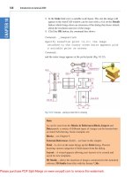
Example – Chamfer and Fillet (Fig. 12.33)
1. Set layer Green as the current layer.
2. Set Isolines to 16.
3. Working to the sizes given in Fig. 12.29 and using the Box and
Cylinder tools, construct the 3D model (Fig. 12.30).
4. Place in the 3D Navigate/SW Isometric view. Union the two
boxes and with the Subtract tool, subtract the cylinders from the
union.
Box 160 � 100 � 10
Box 120 � 60 � 50Cylinders R5
height 10
Elliptical cylinder
80 � 40 height 60
Fig. 12.29 Example – Chamfer and Fillet – sizes for the model
Fig. 12.30 Example – Chamfer and Fillet – isometric view – the model before using the tools
Introducing 3D modeling
chapter 12
243
Notes
To construct the elliptical cylinder, call the Cylinder tool from the
Home/Modeling panel. The command line shows:
Command: _cylinder
Specify center point of base or [3P/2P/Ttr/
Elliptical]: enter e right-click
Specify endpoint of first axis or [Center]:
130,160
Specify other endpoint of first axis: 210,160
Specify endpoint of second axis: 170,180
Specify height or [2Point/Axis endpoint]: 50
Command:
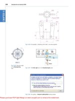
5. Click the Fillet tool icon in the Home/Modify panel (Fig. 12.31).
The command line shows:
Command:_fillet
Current settings: Mode=TRIM. Radius=0
Specify first object or [Undo/Polyline/Radius/
Trim/Multiple]: enter r (Radius) right-click
Specify fillet radius <0>: 10
Select first object: pick one corner
Select an edge or [Chain/Radius]: pick a second
corner
Fig. 12.31 The Fillet tool icon in the Home/Modify panel
Introduction to AutoCAD 2011
chapter 12
244
Select an edge or [Chain/Radius]: pick a third
corner
Select an edge or [Chain/Radius]: pick the
fourth corner
Select an edge or [Chain/Radius]: right-click
4 edge(s) selected for fillet.
Command:
6. Click the Chamfer tool in the Home/Modify panel (Fig. 12.32). The
command line shows:
Command: _chamfer
(TRIM mode) Current chamfer Dist1 = 0, Dist2 = 0
Select first line or [Undo/Polyline/Distance/
Angle/Trim/mEthod/Multiple]: enter d right-click
Specify first chamfer distance <0>: 10
Specify second chamfer distance <10>:
Select first line or [Undo/Polyline/Distance/
Angle/Trim/mEthod/Multiple]: pick one corner
One side of the box highlights
Base surface selection
Enter surface selection option [Next/OK
(current)] <OK>: right-click
Specify base surface chamfer distance <10>:
right-click
Specify other surface chamfer distance <10>:
right-click
Select an edge or [Loop]: pick the edge
Select an edge or [Loop]: pick the second edge
Select an edge [or Loop]: right-click
Command:
Fig. 12.32 The Chamfer tool icon in the Home/Modify panel
Introducing 3D modeling
chapter 12
245
And the edges are chamfered. Repeat to chamfer the other three edges.
7. Place in Visual Styles/Shaded with Edges.
Fig. 12.33 shows the completed 3D model.
Note on the tools Union, Subtract and Intersect
The tools Union, Subtract and Intersect found in the Home/Edit panel
are known as the Boolean operators after the mathematician Boolean.
They can be used to form unions, subtractions or intersection between
extrusions solids of revolution, or any of the 3D Objects.
Constructing 3D surfaces using the Extrude tool
In this example of the construction of a 3D surface model the use of the
Dynamic Input (DYN) method of construction will be shown.
1. Place the AutoCAD drawing area in the 3D Navigation/SW Isometric
view.
2. Click the Dynamic Input button in the status bar to make dynamic
input active.
Example – Dynamic Input (Fig. 12.36)
1. Using the Line tool from the Home/Draw panel construct the outline
(Fig. 12.34).
2. Call the Extrude tool and window the line outline.
3. Extrude to a height of 100.
Fig. 12.33 Example – Fillet and Chamfer
Introduction to AutoCAD 2011
chapter 12
246
The stages of producing the extrusion are shown in Figs 12.34 and 12.35.
The resulting 3D model is a surface model.
Fig. 12.34 Example – constructing the Line outline
Note
The resulting 3D model shown in Fig. 12.35 is a surface model because
the extrusion was constructed from an outline consisting of lines,
which are individual objects in their own right. If the outline had been
a polyline, the resulting 3D model would have been a solid model. The
setting of MOde makes no difference.
The Sweep tool
To call the tool click on its tool icon in the Home/Create panel
(Fig. 12.36).
Introducing 3D modeling
chapter 12
247
Example – Sweep (Fig. 12.38)
1. Construct the pline outline (Fig. 12.37) in the 3D Navigation/Top view.
2. Change to the 3D Navigation/Front view, Zoom to 1 and construct a
pline as shown in Fig. 12.38 as a path central to the outline.
3. Make the layer Magenta current.
4. Place the window in the 3D Navigation/SW Isometric view and click
the Sweep tool icon. The command line shows:
Command: _sweep
Current wire frame density: ISOLINES=4, Closed
profiles creation mode=Solid
Fig. 12.35 Example – Dynamic Input
70
10
10
75
Fig. 12.37 Example
Sweep – the outline to
be swept
Fig. 12.36 Selecting the Sweep tool from the Home/Create panel
Introduction to AutoCAD 2011
chapter 12
248
Select objects to sweep or [MOde]: _MO Closed
profiles creation mode
[SOlid/SUrface] <Solid>: _SO
Select objects to sweep or [MOde]: pick the pline
1 found
Select objects to sweep or [MOde]: right-click
Select sweep path or [Alignment/Base point/Scale/
Twist]: pick the pline path
Command:
5. Place in Visual Styles/Shaded.
The result is shown in Fig. 12.38.
R77
140
R94
130
Fig. 12.38 Example – Sweep
The Loft tool
To call the tool click on its icon in the Home/Create panel.
Example – Loft (Fig. 12.41)
1. In the 3D Navigate/Top view, construct the seven circles shown in
Fig. 12.39 at vertical distances of 30 units apart.
2. Place the drawing area in the 3D Navigate/SW Isometric view.
3. Call the Loft tool with a click on its tool icon in the Home/Modeling
panel (Fig. 12.40).
Introducing 3D modeling
chapter 12
249
4. Set Cyan as the current layer.
5. The command line shows:
Command:_loft
Select cross sections in lofting order or
[POint/Join multiple curves]: pick 1 found
Select cross sections in lofting order or [POint/
Join multiple curves]: pick 1
found, 2 total
Select cross sections in lofting order or [POint/
Join multiple curves]: pick 1
Ø100
Ø80
Ø60
Ø30
Ø60
Ø80
Ø100
Fig. 12.39 Example Loft – the cross sections
Fig. 12.40 Selecting the Loft tool from the Home/Create panel
Introduction to AutoCAD 2011
chapter 12
250
found, 3 total
Select cross sections in lofting order or [POint/
Join multiple curves]: pick 1 found, 4 total
Select cross sections in lofting order or [POint/
Join multiple curves]: pick 1 found, 5 total
Select cross sections in lofting order or [POint/
Join multiple curves]: pick 1 found, 6 total
Select cross sections in lofting order or [POint/
Join multiple curves]: pick 1 found, 7 total
Select cross sections in lofting order or [POint/
Join multiple curves]: enter j right-click
Select curves that are to be joined into a single
cross section: right-click 7 cross sections
selected
Enter an option [Guides/Path/Cross sections only/
Settings] <Cross sections only>: right-click
Command:
6. Place in Visual Styles/Shaded with Edges.
The result is shown in Fig. 12.41.
Fig. 12.41 Example –
Loft
REVISION NOTES
1. In the AutoCAD 3D coordinate system, positive Z is towards the operator away from the
monitor screen.
2. A 3D face is a mesh behind which other details can be hidden.
3. The Extrude tool can be used for extruding closed plines or regions to stated heights, to
stated slopes or along paths.
4. The Revolve tool can be used for constructing solids of revolution through any angle up to
360 degree.
5. 3D models can be constructed from Box, Sphere, Cylinder, Cone, Torus and Wedge.
Extrusions and/or solids of revolutions may form part of models constructed using these
3D tools.
6. The tools Union, Subtract and Intersect are known as the Boolean operators.
7. When polylines form an outline which is not closed are acted upon by the Extrude tool the
resulting models will be 3D Surface models irrespective of the MOde setting.
Introducing AutoCAD 2010
chapter 1
251
Introducing 3D modeling
chapter 12
251
330
130
65 170
Fig. 12.42 Exercise 1 – outline for polyline
Fig. 12.43 Exercise 1
Exercises
Methods of constructing answers to the following exercises can be found in the free website:
/>The exercises which follow require the use of tools from the Home/Create panel in association with tools
from other panels.
1. Fig. 12.42 shows the pline outline from
which the polysolid outline (Fig. 12.43) has
been constructed to a height of 100 and
Width of 3. When the polysolid has been
constructed, construct extrusions which
can then be subtracted from the polysolid.
Sizes of the extrusions are left to your
judgement.
Introduction to AutoCAD 2010
chapter 1
252
Introduction to AutoCAD 2011
chapter 12
252
Fig. 12.46 Exercise 4
10478
45
6
5
2
182
45
R90
R150
R68
12
Fig. 12.47 Exercise 4 – outline drawing
2. Fig. 12.44 shows a 3D model constructed from
four polysolids which have been formed into
a union using the Union tool from the Home/
Modify panel. The original polysolid was
formed from a hexagon of edge length 30.
The original polysolid was of height 40 and
Width 5. Construct the union.
3. Fig. 12.45 shows the 3D model from Exercise 2
acted upon by the Presspull tool from the
Home/Create panel.
With the 3D model from Exercise 2 on screen
and using the Presspull tool, construct the
3D model shown in Fig. 12.45. The distance of
the pull can be estimated.
4. Construct the 3D model of a wine glass
as shown in Fig. 12.46, working to the
dimensions given in the outline drawing
Fig. 12.47.
You will need to construct the outline and change
it into a region before being able to change the
outline into a solid of revolution using the Revolve
tool from the Home/Create panel. This is because
the semi-elliptical part of the outline has been
constructed using the Ellipse tool, resulting in
part of the outline being a spline, which cannot be
acted upon by Polyline Edit to form a closed pline.
Fig. 12.44 Exercise 2
Fig. 12.45 Exercise 3
Introducing AutoCAD 2010
chapter 1
253
Introducing 3D modeling
chapter 12
253
10"
Scale: 10:1 Pline for Revolve of Nozzle
Axis of revolution
−
"
1
4
1−
"
3
8
−
"
3
8
1−
"
5
8
Fig. 12.48 Exercise 5
R0.60"
R0.60"
R0.60"
0.55"
0.45" 0.25"
0.25"
1.20"
1.95"
2.35"3.15"
M0.50"
3.15"
5.30"
5.90"
Ø0.30"
0.25"
1.70"
Fig. 12.49 Exercise 6
5. Fig. 12.48 shows the outline from which a
solid of revolution can be constructed. Using
the Revolve tool from the Home/Create
panel to construct the solid of revolution.
6. Construct a 3D solid model of a bracket
working to the information given in Fig. 12.49.
7. Working to the dimensions given in Fig. 12.50
construct an extrusion of the plate to a height
of 5 units.
8. Working to the details given in the
orthographic projection (Fig. 12.51),
construct a 3D model of the assembly. After
Introduction to AutoCAD 2010
chapter 1
254
Introduction to AutoCAD 2011
chapter 12
254
10
160
10
20
Ø110
Ø135
Ø165
Ø20
Ø40
20
30
2.5
R2.5
11.5
2.5
R2.5
17.5
10
Detail at A (Scale 2:1)
Detail at B (Scale 2:1)
A
B
Ø55
Ø80
5
Fig. 12.51 Exercise 8
constructing the pline outline(s) required for
the solid(s) of revolution, use the Revolve tool
to form the 3D solid.
9. Working to the polylines shown in Fig. 12.52
construct the Sweep shown in Fig. 12.53.
10. Construct the cross sections as shown in the
left-hand drawing of Fig. 12.54 working to
suitable dimensions. From the cross sections
construct the lofts shown in the right-hand
view. The lofts are topped with a sphere
constructed using the Sphere tool.
250
110
160
80
R50
Fig. 12.50 Exercise 7
Introducing AutoCAD 2010
chapter 1
255
Introducing 3D modeling
chapter 12
255
10
50
155 155
15
15
Profile outline Path
Fig. 12.52 Exercise 9 – profile and path dimensions
Fig. 12.53 Exercise 9
Fig. 12.54 The cross sections for Exercise 10
257
AIM OF THIS CHAPTER
The aim of this chapter is to give examples of 3D solid models constructed in multiple view-
port settings.
Chapter 13
3D models in
viewports
Introduction to AutoCAD 2011
chapter 13
258
The 3D Modeling workspace
In Chapter 12 all 3D model actions were constructed in the 3D Basics
workspace. As shown in that chapter, a large number of different types of
3D models can be constructed in that workspace. In the following chapters
3D models will be constructed in the 3D Modeling workspace, brought
to screen with a click on 3D Modeling icon the Workspace Settings
menu (Fig. 13.1). The AutoCAD window assumes the selected workspace
settings (Fig. 13.2).
Fig. 13.1 Opening the 3D Modeling workspace
Fig. 13.2 The 3D Modeling workspace in SW Isometric view and Grid on
3D models in viewports
3
chapter 13
259
If the 3D Modeling workspace is compared with the 3D Basics workspace
(Fig. 12.2, page 225) it will be seen that there are several new tabs which
when click ed bring changes in the ribbon with different sets of panels. In
Fig. 13.2 the menu bar is included. This need not be included if the operator
does not need the drop-down menus available from the menu bar.
Setting up viewport systems
One of the better methods of constructing 3D models is in different
multiple viewports. This allows what is being constructed to be seen from
a variety of viewing positions. To set up multiple viewports.
In the 3D Modeling workspace click New in the View/Viewports panel.
From the popup list which appears (Fig. 13.3) select Four: Equal. The
Four: Equal viewports layout appears (Fig. 13.4).
Fig. 13.3 Selecting
Four: Equal from the
View/Viewports popup
list
Fig. 13.4 The Four: Equal viewports layout
In Fig. 13.4 a simple 3D model has been constructed in the Four: Equal
viewport layout. It will be seen that each viewport has a different view of
the 3D model. Top right is an isometric view. Bottom right is a view from
the right of the model. Bottom left is a view from the left of the model.
Introduction to AutoCAD 2011
chapter 13
260
Top left is a view from the top of the model. Note that the front view
viewport is surrounded by a thicker line than the other three, which means
it is the current viewport. Any one of the four viewports can be made
current with a left-click within its boundary. Note also that three of the
views are in third angle projection.
When a viewport system has been opened it will usually be necessary
to make each viewport current in turn and Zoom and Pan to ensure that
views fit well within their boundaries.
If a first angle layout is needed it will be necessary to open the Viewports
dialog (Fig. 13.5) with a click on the New icon in the View/Viewports
panel (Fig. 13.6). First select Four: Equal from the Standard
viewports list; select 3D from the Setup popup menu; click in the top
right viewport and select Left in the Change View popup list; enter
first angle in the New name field. Change the other viewports as shown.
Save the settings with a click on the Named Viewports tab and enter the
required name for the setup in the sub-dialog which appears.
Fig. 13.5 The Viewports dialog set for a 3D first angle Four: Equal setting
3D models in viewports
3
chapter 13
261
Fig. 13.6 Selecting New from the View/Viewports panel
First example – Four: Equal viewports (Fig. 13.9)
Fig. 13.7 shows a two-view orthographic projection of a support. To
construct a Scale 1:1 third angle 3D model of the support in a Four Equal
viewport setting on a layer colour Blue:
1. Open a Four Equal viewport setting from the New popup list in the
View/Viewports panel (Fig. 13.3).
2. Click in each viewport in turn, making the selected viewport active, and
Zoom to 1.
Fig. 13.7 First example – orthographic projection of the support
Scale: Date: Title:
DO NOT SCALEDimensions in millimetres
Holes Ø20
HOLE Ø40
30
10
160
20
30
6030
160
R20
30
Name:
A. Student 1.2
23.11.2005
Support 45/D
Introduction to AutoCAD 2011
chapter 13
262
3. Using the Polyline tool, construct the outline of the plan view of the
plate of the support, including the holes in the Top viewport (Fig. 13.5).
Note the views in the other viewports.
4. Call the Extrude tool from the Home/Modeling panel and extrude the
plan outline and the circles to a height of 20.
5. With Subtract from the Home/Solid Editing panel, subtract the holes
from the plate (Fig. 13.8).
Fig. 13.8 First example – the four viewports after Extrude and Subtract
6. Call the Box tool and in the centre of the plate construct a box of
Width60, Length60 and Height30.
7. Call the Cylinder tool and in the centre of the box construct a cylinder
of Radius20 and of Height30.
8. Call Subtract and subtract the cylinder from the box.
9. Click in the Right viewport, with the Move tool, move the box and its
hole into the correct position with regard to the plate.
10. With Union, form a union of the plate and box.
11. Click in the Front viewport and construct a triangle of one of the webs
attached between the plate and the box. With Extrude, extrude the
triangle to a height of 10. With the Mirror tool, mirror the web to the
other side of the box.
12. Click in the Right viewport and with the Move tool, move the two
webs into their correct position between the box and plate. Then, with
Union, form a union between the webs and the 3D model.
13. In the Right viewport, construct the other two webs and in the Front
viewport, move, mirror and union the webs as in steps 11 and 12.
Fig. 13.9 shows the resulting four-viewport scene.
3D models in viewports
3
chapter 13
263
Second example – Four: Left viewports (Fig. 13.11)
1. Open a Four: Left viewport layout from the Views/Viewports popup
list (Fig. 13.3).
2. Make a new layer of colour Magenta and make that layer current.
3. In the Top viewport construct an outline of the web of the Support
Bracket shown in Fig. 13.10. With the Extrude tool, extrude the parts
of the web to a height of 20.
4. With the Subtract tool, subtract the holes from the web.
Fig. 13.9 First example – Four: Equal viewports
Name: Scale: Date: Title:
A. Reader 1:1 12/09/2006 Support Bracket 3/A
Dimensions in millimetres DO NOT SCALE
300
20
Holes Ø20
R15
10
R5
R50
10
Hole Ø80
60
80
R60
30
Fig. 13.10 Working drawing for the second example
Introduction to AutoCAD 2011
chapter 13
264
5. In the Top viewport, construct two cylinders central to the extrusion,
one of radius 50 and height 30, the second of radius 40 and height 30.
With the Subtract tool, subtract the smaller cylinder from the larger.
6. Click in the Front viewport and move the cylinders vertically by 5
units. With Union form a union between the cylinders and the web.
7. Still in the Front viewport and at one end of the union, construct two
cylinders, the first of radius 10 and height 80, the second of radius 15
and height 80. Subtract the smaller from the larger.
8. With the Mirror tool, mirror the cylinders to the other end of the union.
9. Make the Top viewport current and with the Move tool, move the
cylinders to their correct position at the ends of the union. Form a
union between all parts on screen.
10. Make the Isometric viewport current. From the View/Visual Styles
panel select Conceptual.
Fig. 13.11 shows the result.
Fig. 13.11 Second example – Four: Left viewports
Third example – Three: Right viewports (Fig. 13.13)
1. Open the Three: Right viewport layout from the View/Viewports
popup list (Fig. 13.3).
2. Make a new layer of colour Green and make that layer current.
3. In the Front viewport (top left-hand), construct a pline outline to the
dimensions in Fig. 13.12.
4. Call the Revolve tool from the Home/Modeling panel and revolve the
outline through 360 degree.
5. From the View/Visual Styles panel select Conceptual.
The result is shown in Fig. 13.13.
3D models in viewports
3
chapter 13
265
Fig. 13.13 Third example – Three: Right viewports
Notes
1. When working in viewport layouts, make good use of the Zoom
tool, because the viewports are smaller than a single viewport in
AutoCAD 2011.
2. As in all other forms of constructing drawings in AutoCAD 2011
frequent toggling of SNAP, ORTHO and GRID will allow speedier
and more accurate working.
REVISION NOTES
1. Outlines suitable for use when constructing 3D models can be constructed using the 2D
tools such as Line, Arc, Circle and polyline. Such outlines must either be changed to closed
polylines or to regions before being incorporated in 3D models.
2. The use of multiple viewports can be of value when constructing 3D models in that
various views of the model appear enabling the operator to check the accuracy of the 3D
appearance throughout the construction period.
Chamfer 20x20
5
25
30
340
5
35
55 65
100
20
Fig. 13.12 Third example – outline for solid of revolution
Introduction to AutoCAD 2010
chapter 1
266
Introduction to AutoCAD 2011
3
chapter 13
266
Fig. 13.14 Exercise 1
48
55
Ø40
Sphere Ø140
Ø50
Hole 55xØ30
Semi-sphere R50
70
Fig. 13.15 Exercise 2 – working drawing
Fig. 13.16 Exercise 2
Exercises
Methods of constructing answers to the following exercises can be found in the free website:
/>1. Using the Cylinder, Box, Sphere, Wedge and Fillet tools, together with the Union and Subtract tools
and working to any sizes thought suitable, construct the ‘head’ as shown in the Three: Right viewport
as shown in Fig. 13.12 (Fig. 13.14).
2. Using the tools Sphere, Box, Union and
Subtract and working to the dimensions given
in Fig. 13.15, construct the 3D solid model as
shown in the isometric drawing Fig. 13.16.
3. Each link of the chain shown in Fig. 13.17 has
been constructed using the tool
Extrude and
extruding a small circle along an elliptical
path. Copies of the link were then made, half
Introducing AutoCAD 2010
chapter 1
267
Introducing AutoCAD 2011
chapter 13
267
Fig. 13.17 Exercise 3
of which were rotated in a Right view and
then moved into their position relative to the
other links. Working to suitable sizes construct
a link and from the link construct the chain as
shown.
4. A two-view orthographic projection of a
rotatable lever from a machine is given in
Fig. 13.18 together with an isometric drawing
of the 3D model constructed to the details
given in the drawing Fig. 13.19.
5. Construct the 3D model drawing in a Four:
Equal viewport setting.
R0.40''
0.40''
0.40''
R2.00''
R0.30''
2.00''
1'-1.95''
Ø2.40''
3.80''
0.80''
3.30''
R2'-6.30''
Fig. 13.18 Exercise 4 – orthographic projection
Fig. 13.19 Exercise 4
Holes SQ 9
Keyway 9X9
Hole Ø40
R4
Ø180
Ø150
Ø105
Ø60
23
11
Dimensions in millimetres
M.Y.Name Scale 1:1 27/05/2008 FACE PLATE 7/FC
Fig. 13.20 Exercise 5 – dimensions
Fig. 13.21 Exercise 5
6. Working in a Three: Left viewport setting,
construct a 3D model of the faceplate to
the dimensions given in Fig. 13.20. With
the Mirror tool, mirror the model to obtain
an opposite facing model. In the Isometric
viewport call the Hide tool (Fig. 13.21).