Sequential Verulog Topics part 8 ppsx
Bạn đang xem bản rút gọn của tài liệu. Xem và tải ngay bản đầy đủ của tài liệu tại đây (57.78 KB, 15 trang )
13.3 Internal Data Representation
Before we understand how to use PLI library routines, it is first necessary to
describe how a design is viewed internally in the simulator. Each module is viewed
as a collection of object types. Object types are elements defined in Verilog, such
as:
• Module instances, module ports, module pin-to-pin paths, and intermodule
paths
• Top-level modules
• Primitive instances, primitive terminals
• Nets, registers, parameters, specparams
• Integer, time, and real variables
• Timing checks
• Named events
Each object type has a corresponding set that identifies all objects of that type in
the module. Sets of all object types are interconnected.
A conceptual internal representation of a module is shown in Figure 13-3
.
Figure 13-3. Conceptual Internal Representation a Module
Each set contains all elements of that object type in the module. All sets are
interconnected. The connections between the sets are bidirectional. The entire
internal representation can be traversed by using PLI library routines to obtain
information about the module. PLI library routines are discussed later in the
chapter.
To illustrate the internal data representation, consider the example of a simple 2-to-
1 multiplexer whose gate level circuit is shown in Figure 13-4
.
Figure 13-4. 2-to-1 Multiplexer
The Verilog description of the circuit is shown in Example 13-1
.
Example 13-1 Verilog Description of 2-to-1 Multiplexer
module mux2_to_1(out, i0, i1, s);
output out; //output port
input i0, i1; //input ports
input s;
wire sbar, y1, y2; //internal nets
//Gate Instantiations
not n1(sbar, s);
and a1(y1, i0, sbar);
and a2(y2, i1, s);
or o1(out, y1, y2);
endmodule
The internal data representation for the 2-to-1 multiplexer is shown in Figure 13-5
.
Sets are shown for primitive instances, primitive instance terminals, module ports,
and nets. Other object types are not present in this module.
Figure 13-5. Internal Data Representation of 2-to-1 Multiplexer
The example shown above does not contain register, integers, module instances,
and other object types. If they are present in a module definition, they are also
represented in terms of sets. This description is a conceptual view of the internal
structures. The exact implementation of data structures is simulator dependent.
[ Team LiB ]
[ Team LiB ]
13.4 PLI Library Routines
PLI library routines provide a standard interface to the internal data representation
of the design. The user-defined C routines for user-defined system tasks are written
by using PLI library routines. In the example in Section 13.2
, Linking and
Invocation of PLI Tasks, $hello_verilog is the user-defined system task,
hello_verilog is the user-defined C routine, and io_printf is a PLI library routine.
There are two broad classes of PLI library routines: access routines and utility
routines. (Note that vpi_ routines are a superset of access and utility routines and
are not discussed in this book.)
Access routines provide access to information about the internal data
representation; they allow the user C routine to traverse the data structure and
extract information about the design. Utility routines are mainly used for passing
data across the Verilog/Programming Language Boundary and for miscellaneous
housekeeping functions. Figure 13-6
shows the role of access and utility routines in
PLI.
Figure 13-6. Role of Access and Utility Routines
A complete list of PLI library routines is provided in Appendix B
, List of PLI
Routines. The function and usage of each routine are also specified.
13.4.1 Access Routines
Access routines are also popularly called acc routines. Access routines can do the
following:
• Read information about a particular object from the internal data
representation
• Write information about a particular object into the internal data
representation
We will discuss only reading of information from the design. Information about
modifying internal design representation can be found in the Programming
Language Interface (PLI) Manual. However, reading of information is adequate for
most practical purposes.
Access routines can read information about objects in the design. Objects can be
one of the following types:
• Module instances, module ports, module pin-to-pin paths, and intermodule
paths
• Top-level modules
• Primitive instances, primitive terminals
• Nets, registers, parameters, specparams
• Integer, time, and real variables
• Timing checks
• Named events
Mechanics of access routines
Some observations about access routines are listed below.
• Access routines always start with the prefix acc_.
• A user-defined C routine that uses access routines must first initialize the
environment by calling the routine acc_initialize(). When exiting, the user-
defined C routine must call acc_close().
• If access routines are being used in a file, the header file acc_user.h must
also be included. All access routine data types and constants are predefined
in the file acc_user.h.
• #include "acc_user.h"
• Access routines use the concept of a handle to access an object. Handles are
predefined data types that point to specific objects in the design. Any
information about the object can be obtained once the object handle is
obtained. This is similar to the concept of file handles for accessing files in
C programs. An object handle identifier is declared with the keyword
handle.
handle top_handle;
Types of access routines
We discuss six types of access routines.
• Handle routines. They return handles to objects in the design. The name of
handle routines always starts with the prefix acc_handle_.
• Next routines. They return the handle to the next object in the set of a given
object type in a design. Next routines always start with the prefix acc_next_
and accept reference objects as arguments.
• Value Change Link (VCL) routines. They allow the user system task to add
and delete objects from the list of objects that are monitored for value
changes. VCL routines always begin with the prefix acc_vcl_ and do not
return a value.
• Fetch routines. They can extract a variety of information about objects.
Information such as full hierarchical path name, relative name, and other
attributes can be obtained. Fetch routines always start with the prefix
acc_fetch_.
• Utility access routines. They perform miscellaneous operations related to
access routines. For example, acc_initialize() and acc_close() are utility
routines.
• Modify routines. They can modify internal data structures. We do not
discuss them in this book. Refer to the IEEE Standard Verilog Hardware
Description Language document for details about modify routines.
A complete list of access routines and their usage is provided in Appendix B
, List
of PLI Routines.
Examples of access routines
We will discuss two examples that illustrate the use of access routines. The first
example is a user-defined system task to find names of all ports in a module and
count the number of ports. The second example is a user-defined system task that
monitors the changes in values of nets.
Example 1: Get Module Port List
Let us write a user-defined system task $get_ports to find complete hierarchical
names of input, output, and inout ports in a module and to count the number of
input, output, and inout ports. The user-defined system task will be invoked in
Verilog as $get_ports("<hierarchical_module_name>"). The user-defined C routine
get_ports, which implements the task $get_ports, is described in file get_ports.c.
The file get_ports.c is shown in Example 13-3
.
Example 13-2 PLI Routine to get Module Port List
#include "acc_user.h"
int get_ports()
{
handle mod, port;
int input_ctr = 0;
int output_ctr = 0;
int inout_ctr = 0;
acc_initialize();
mod = acc_handle_tfarg(1); /* get a handle to the module instance
first argument in the system task argument
list */
port = acc_handle_port(mod, 0); /* get the first port of the module */
while( port != null ) /* loop for all ports */
{
if (acc_fetch_direction(port) == accInput) /* Input port */
{
io_printf("Input Port %s \n", acc_fetch_fullname(port));
/* full hierarchical name */
input_ctr++;
}
else if (acc_fetch_direction(port) == accOutput) /* Output port */
{
io_printf("Output Port %s \n", acc_fetch_fullname(port));
output_ctr++;
}
else if (acc_fetch_direction(port) == accInout) /* Inout port */
{
io_printf("Inout Port %s \n", acc_fetch_fullname(port));
inout_ctr++;
}
port = acc_next_port(mod, port); /* go to the next port */
}
io_printf("Input Ports = %d Output Ports = %d, Inout ports = %d\n\n",
input_ctr, output_ctr, inout_ctr);
acc_close();
}
N
otice that handle, fetch, next, and utility access routines are used to write the user
C routine.
Link the new task into the Verilog simulator as described in Section 13.2.1
,
Linking PLI Tasks. To check the newly defined task, we will use it to find out the
p
ort list of the module mux2_to_1 described in Example 13-1. A top-level module
that instantiates the 2-to-1 multiplexer and invokes the $get_ports task is shown
below.
module top;
wire OUT;
reg I0, I1, S;
mux2_to_1 my_mux(OUT, I0, I1, S); /*Instantiate the 2-to-1 mux*/
initial
begin
$get_ports("top.my_mux"); /*invoke task $get_ports to get port list*/
end
endmodule
Invocation of $get_ports causes the user C routine $get_ports to be executed. The
output of the simulation is shown below.
Output Port top.my_mux.out
Input Port top.my_mux.i0
Input Port top.my_mux.i1
Input Port top.my_mux.s
Input Ports = 3 Output Ports = 1, Inout ports = 0
Example 2: Monitor Nets for Value Changes
This example highlights the use of Value Change Link (VCL) routines. Instead of
using the $monitor task provided with the Verilog simulator, let us define our own
task to monitor specific nets in the design for value changes. The task
$my_monitor("<net_name>"); is to be invoked to add a <net_name> to the
monitoring list.
The user-defined C routine my_monitor, which implements the user-defined
system task, is shown in Example 13-3
.
Example 13-3 PLI Routine to Monitor Nets for Value Changes
#include "acc_user.h"
char convert_to_char();
int display_net();
int my_monitor()
{
handle net;
char *netname ; /*pointer to store names of nets*/
char *malloc();
acc_initialize(); /*initialize environment*/
net = acc_handle_tfarg(1); /*get a handle to the net to be monitored*/
/*Find hierarchical name of net and store it*/
netname = malloc(strlen(acc_fetch_fullname(net)));
strcpy(netname, acc_fetch_fullname(net));
/* Call the VCL routine to add a signal to the monitoring list*/
/* Pass four arguments to acc_vcl_add task*/
/* 1st : handle to the monitored object (net)
2nd : Consumer C routine to call when the object value changes (display_net)
3rd : String to be passed to consumer C routine (netname)
4th : Predefined VCL flags: vcl_verilog_logic for logic monitoring
vcl_verilog_strength for strength monitoring */
acc_vcl_add(net, display_net, netname, vcl_verilog_logic);
acc_close();
}
N
otice that the net is added to the monitoring list with the routine acc_vcl_add. A
consumer routine display_net is an argument to acc_vcl_add. Whenever the value
of the net changes, the acc_vcl_add calls the consumer routine display_net and
p
asses a pointer to a data structure of the type p_vc_record. A consumer routine is
a C routine that performs an action determined by the user whenever acc_vcl_add
calls it. The p_vc_record is predefined in the acc_user.h file, as shown below.
typedef struct t_vc_record{
int vc_reason; /*reason for value change*/
int vc_hightime; /*Higher 32 bits of 64-bit simulation time*/
int vc_lowtime; /*Lower 32 bits of 64-bit simulation time*/
char *user_data; /*String passed in 3rd argument of acc_vcl_add*/
union { /*New value of the monitored signal*/
unsigned char logic_value;
double real_value;
handle vector_handle;
s_strengths strengths_s;
} out_value;
} *p_vc_record;
The consumer routine display_net simply displays the time of change, name of net,
and new value of the net. The consumer routine is written as shown in Example
13-4. Another routine, convert_to_char, is defined to convert the logic value
constants to an ASCII character.
Example 13-4 Consumer Routine for VCL Example
/*Consumer routine. Called whenever any monitored net changes*/
display_net(vc_record)
p
_vc_record vc_record; /*Structure p_vc_record predefined in
acc_user.h*/
{
/*Print time, name, and new value of the changed net */
io_printf("%d New value of net %s is %c \n",
vc_record->vc_lowtime,
vc_record->user_data,
convert_to_char(vc_record->out_value.logic_value));
}
/*Miscellaneous routine to convert predefined character constant to
ASCII character*/
char convert_to_char(logic_val)
char logic_val;
{
char temp;
switch(logic_val)
{
/*vcl0, vcl1, vclX and vclZ are predefined in acc_user.h*/
case vcl0: temp='0';
break;
case vcl1: temp='1';
break;
case vclX: temp='X';
break;
case vclZ: temp='Z';
break;
}
return(temp);
}
Link the new task into the Verilog simulator as described in Section 13.2.1
,
Linking PLI Tasks. To check the newly defined task, we will use it to monitor nets
sbar and y1 when stimulus is applied to module mux2_to_1 described in Example
13-1 on page 281. A top-level module that instantiates the 2-to-1 multiplexer,
applies stimulus, and invokes the $my_monitor task is shown below.
module top;
wire OUT;
reg I0, I1, S;
mux2_to_1 my_mux(OUT, I0, I1, S); //Instantiate the module mux2_to_1
initial //Add nets to the monitoring list
begin
$my_monitor("top.my_mux.sbar");
$my_monitor("top.my_mux.y1");
end
initial //Apply Stimulus
begin
I0=1'b0; I1=1'b1; S = 1'b0;
#5 I0=1'b1; I1=1'b1; S = 1'b1;
#5 I0=1'b0; I1=1'b1; S = 1'bx;
#5 I0=1'b1; I1=1'b1; S = 1'b1;
end
endmodule
The output of the simulation is shown below.
0 New value of net top.my_mux.y1 is 0
0 New value of net top.my_mux.sbar is 1
5 New value of net top.my_mux.y1 is 1
5 New value of net top.my_mux.sbar is 0
5 New value of net top.my_mux.y1 is 0
10 New value of net top.my_mux.sbar is X
15 New value of net top.my_mux.y1 is X
15 New value of net top.my_mux.sbar is 0
15 New value of net top.my_mux.y1 is 0
13.4.2 Utility Routines
Utility routines are miscellaneous PLI routines that pass data in both directions
across the Verilog/user C routine boundary. Utility routines are also popularly
called "tf" routines.
Mechanics of utility routines
Some observations about utility routines are listed below.
• Utility routines always start with the prefix tf_.
• If utility routines are being used in a file, the header file veriuser.h must be
included. All utility routine data types and constants are predefined in
veriuser.h.
#include "veriuser.h"
Types of utility routines
Utility routines are available for the following purposes:
• Get information about the Verilog system task invocation
• Get argument list information
• Get values of arguments
• Pass back new values of arguments to calling system task
• Monitor changes in values of arguments
• Get information about simulation time and scheduled events
• Perform housekeeping tasks, such as saving work areas, and storing pointers
to tasks
• Do long arithmetic
• Display messages
• Halt, terminate, save, and restore simulation
A list of utility routines, their function, and usage is provided in Appendix B.
Example of utility routines
Until now we encountered only one utility routine, io_printf(). Now we will look at
a few more utility routines that allow passing of data between the Verilog design
and the user-defined C routines.
Verilog provides the system tasks $stop and $finish that suspend and terminate the
simulation. Let us define our own system task, $my_stop_finish, which does both
stopping and finishing based on the arguments passed to it. The complete
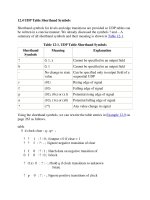
specifications for the user-defined system task $my_stop_finish are shown in Table
13-1.
Table 13-1. Specifications for $my_stop_finish
1st
Argument
2nd
Argument
Action
0 none Stop simulation. Display simulation time and
message.
1 none Finish simulation. Display simulation time and
message.
0 any value Stop simulation. Display simulation time, module
instance from which stop was called, and message.
1 any value Finish simulation. Display simulation time, module
instance from which stop was called, and message.
The source code for the user-defined C routine my_stop_finish is shown in
Example 13-5
.
Example 13-5 User C Routine my_stop_finish, Using Utility Routines
#include "veriuser.h"
int my_stop_finish()
{
if(tf_nump() == 1) /* if 1 argument is passed to the my_stop_finish
task, display only simulation time and message*/
{
if(tf_getp(1) == 0) /* get value of argument. If the argument
is 0, then stop the simulation*/
{
io_printf("Mymessage: Simulation stopped at time %d\n",
tf_gettime());
tf_dostop(); /*stop the simulation*/
}
else if(tf_getp(1) == 1) /* if the argument is 0 then terminate
the simulation*/
{
io_printf("Mymessage: Simulation finished at time %d\n",
tf_gettime());
tf_dofinish(); /*terminate the simulation*/
}
else
/* Pass warning message */
tf_warning("Bad arguments to \$my_stop_finish at time %d\n",
tf_gettime());
}
else if(tf_nump() == 2) /* if 1 argument is passed to the my_stop_finish
task, then print module instance from which the
task was called, time and message */
{
if(tf_getp(1) == 0) /* if the argument is 0 then stop
the simulation*/
{
io_printf
("Mymessage: Simulation stopped at time %d in instance %s \n",
tf_gettime(), tf_mipname());
tf_dostop(); /*stop the simulation*/
}
else if(tf_getp(1) == 1) /* if the argument is 0 then terminate
the simulation*/
{
io_printf
("Mymessage: Simulation finished at time %d in instance %s \n",
tf_gettime(), tf_mipname());
tf_dofinish(); /*terminate the simulation*/
}
else
/* Pass warning message */
tf_warning("Bad arguments to \$my_stop_finish at time %d\n",
tf_gettime());
}
}
Link the new task into the Verilog simulator as described in Section 13.2.1
,
Linking PLI Tasks. To check the newly defined task $my_stop_finish, a stimulus
in which $my_stop_finish is called with all possible combinations of arguments is
applied to the module mux2_to_1 described in Example 13-1
on page 281. A top-
level module that instantiates the 2-to-1 multiplexer, applies stimulus, and invokes
the $my_stop_finish task is shown below.
module top;
wire OUT;
reg I0, I1, S;
mux2_to_1 my_mux(OUT, I0, I1, S); //Instantiate the module mux2_to_1
initial //Apply Stimulus
begin
I0=1'b0; I1=1'b1; S = 1'b0;
$my_stop_finish(0); //Stop simulation. Don't print module instance name
#5 I0=1'b1; I1=1'b1; S = 1'b1;
$my_stop_finish(0,1); //Stop simulation. Print module instance name
#5 I0=1'b0; I1=1'b1; S = 1'bx;
$my_stop_finish(2,1); //Pass bad argument 2 to the task
#5 I0=1'b1; I1=1'b1; S = 1'b1;
$my_stop_finish(1,1); //Terminate simulation. Print module instance
//name
end
endmodule
The output of the simulation with a Verilog simulator is shown below.
Mymessage: Simulation stopped at time 0
Type ? for help
C1 > .
Mymessage: Simulation stopped at time 5 in instance top
C1 > .
"my_stop_finish.v", 14: warning! Bad arguments to $my_stop_finish at time 10
Mymessage: Simulation finished at time 15 in instance top